EP2110526B1 - Abgasreiniger für einen verbrennungsmotor - Google Patents
Abgasreiniger für einen verbrennungsmotor Download PDFInfo
- Publication number
- EP2110526B1 EP2110526B1 EP08704384A EP08704384A EP2110526B1 EP 2110526 B1 EP2110526 B1 EP 2110526B1 EP 08704384 A EP08704384 A EP 08704384A EP 08704384 A EP08704384 A EP 08704384A EP 2110526 B1 EP2110526 B1 EP 2110526B1
- Authority
- EP
- European Patent Office
- Prior art keywords
- trap catalyst
- catalyst
- amount
- trap
- exhaust gas
- Prior art date
- Legal status (The legal status is an assumption and is not a legal conclusion. Google has not performed a legal analysis and makes no representation as to the accuracy of the status listed.)
- Not-in-force
Links
Images


Classifications
-
- F—MECHANICAL ENGINEERING; LIGHTING; HEATING; WEAPONS; BLASTING
- F02—COMBUSTION ENGINES; HOT-GAS OR COMBUSTION-PRODUCT ENGINE PLANTS
- F02D—CONTROLLING COMBUSTION ENGINES
- F02D41/00—Electrical control of supply of combustible mixture or its constituents
- F02D41/02—Circuit arrangements for generating control signals
- F02D41/021—Introducing corrections for particular conditions exterior to the engine
- F02D41/0235—Introducing corrections for particular conditions exterior to the engine in relation with the state of the exhaust gas treating apparatus
- F02D41/027—Introducing corrections for particular conditions exterior to the engine in relation with the state of the exhaust gas treating apparatus to purge or regenerate the exhaust gas treating apparatus
- F02D41/0285—Introducing corrections for particular conditions exterior to the engine in relation with the state of the exhaust gas treating apparatus to purge or regenerate the exhaust gas treating apparatus the exhaust gas treating apparatus being a SOx trap or adsorbent
-
- B—PERFORMING OPERATIONS; TRANSPORTING
- B01—PHYSICAL OR CHEMICAL PROCESSES OR APPARATUS IN GENERAL
- B01D—SEPARATION
- B01D53/00—Separation of gases or vapours; Recovering vapours of volatile solvents from gases; Chemical or biological purification of waste gases, e.g. engine exhaust gases, smoke, fumes, flue gases, aerosols
- B01D53/34—Chemical or biological purification of waste gases
- B01D53/92—Chemical or biological purification of waste gases of engine exhaust gases
- B01D53/94—Chemical or biological purification of waste gases of engine exhaust gases by catalytic processes
- B01D53/9459—Removing one or more of nitrogen oxides, carbon monoxide, or hydrocarbons by multiple successive catalytic functions; systems with more than one different function, e.g. zone coated catalysts
- B01D53/9477—Removing one or more of nitrogen oxides, carbon monoxide, or hydrocarbons by multiple successive catalytic functions; systems with more than one different function, e.g. zone coated catalysts with catalysts positioned on separate bricks, e.g. exhaust systems
-
- F—MECHANICAL ENGINEERING; LIGHTING; HEATING; WEAPONS; BLASTING
- F01—MACHINES OR ENGINES IN GENERAL; ENGINE PLANTS IN GENERAL; STEAM ENGINES
- F01N—GAS-FLOW SILENCERS OR EXHAUST APPARATUS FOR MACHINES OR ENGINES IN GENERAL; GAS-FLOW SILENCERS OR EXHAUST APPARATUS FOR INTERNAL-COMBUSTION ENGINES
- F01N13/00—Exhaust or silencing apparatus characterised by constructional features
- F01N13/009—Exhaust or silencing apparatus characterised by constructional features having two or more separate purifying devices arranged in series
-
- F—MECHANICAL ENGINEERING; LIGHTING; HEATING; WEAPONS; BLASTING
- F01—MACHINES OR ENGINES IN GENERAL; ENGINE PLANTS IN GENERAL; STEAM ENGINES
- F01N—GAS-FLOW SILENCERS OR EXHAUST APPARATUS FOR MACHINES OR ENGINES IN GENERAL; GAS-FLOW SILENCERS OR EXHAUST APPARATUS FOR INTERNAL-COMBUSTION ENGINES
- F01N3/00—Exhaust or silencing apparatus having means for purifying, rendering innocuous, or otherwise treating exhaust
- F01N3/08—Exhaust or silencing apparatus having means for purifying, rendering innocuous, or otherwise treating exhaust for rendering innocuous
- F01N3/0807—Exhaust or silencing apparatus having means for purifying, rendering innocuous, or otherwise treating exhaust for rendering innocuous by using absorbents or adsorbents
- F01N3/0828—Exhaust or silencing apparatus having means for purifying, rendering innocuous, or otherwise treating exhaust for rendering innocuous by using absorbents or adsorbents characterised by the absorbed or adsorbed substances
- F01N3/0842—Nitrogen oxides
-
- F—MECHANICAL ENGINEERING; LIGHTING; HEATING; WEAPONS; BLASTING
- F01—MACHINES OR ENGINES IN GENERAL; ENGINE PLANTS IN GENERAL; STEAM ENGINES
- F01N—GAS-FLOW SILENCERS OR EXHAUST APPARATUS FOR MACHINES OR ENGINES IN GENERAL; GAS-FLOW SILENCERS OR EXHAUST APPARATUS FOR INTERNAL-COMBUSTION ENGINES
- F01N3/00—Exhaust or silencing apparatus having means for purifying, rendering innocuous, or otherwise treating exhaust
- F01N3/08—Exhaust or silencing apparatus having means for purifying, rendering innocuous, or otherwise treating exhaust for rendering innocuous
- F01N3/0807—Exhaust or silencing apparatus having means for purifying, rendering innocuous, or otherwise treating exhaust for rendering innocuous by using absorbents or adsorbents
- F01N3/0828—Exhaust or silencing apparatus having means for purifying, rendering innocuous, or otherwise treating exhaust for rendering innocuous by using absorbents or adsorbents characterised by the absorbed or adsorbed substances
- F01N3/085—Sulfur or sulfur oxides
-
- B—PERFORMING OPERATIONS; TRANSPORTING
- B01—PHYSICAL OR CHEMICAL PROCESSES OR APPARATUS IN GENERAL
- B01D—SEPARATION
- B01D2251/00—Reactants
- B01D2251/20—Reductants
- B01D2251/208—Hydrocarbons
-
- B—PERFORMING OPERATIONS; TRANSPORTING
- B01—PHYSICAL OR CHEMICAL PROCESSES OR APPARATUS IN GENERAL
- B01D—SEPARATION
- B01D2255/00—Catalysts
- B01D2255/10—Noble metals or compounds thereof
- B01D2255/102—Platinum group metals
- B01D2255/1021—Platinum
-
- B—PERFORMING OPERATIONS; TRANSPORTING
- B01—PHYSICAL OR CHEMICAL PROCESSES OR APPARATUS IN GENERAL
- B01D—SEPARATION
- B01D2257/00—Components to be removed
- B01D2257/30—Sulfur compounds
- B01D2257/302—Sulfur oxides
-
- B—PERFORMING OPERATIONS; TRANSPORTING
- B01—PHYSICAL OR CHEMICAL PROCESSES OR APPARATUS IN GENERAL
- B01D—SEPARATION
- B01D2257/00—Components to be removed
- B01D2257/40—Nitrogen compounds
- B01D2257/404—Nitrogen oxides other than dinitrogen oxide
-
- F—MECHANICAL ENGINEERING; LIGHTING; HEATING; WEAPONS; BLASTING
- F01—MACHINES OR ENGINES IN GENERAL; ENGINE PLANTS IN GENERAL; STEAM ENGINES
- F01N—GAS-FLOW SILENCERS OR EXHAUST APPARATUS FOR MACHINES OR ENGINES IN GENERAL; GAS-FLOW SILENCERS OR EXHAUST APPARATUS FOR INTERNAL-COMBUSTION ENGINES
- F01N2550/00—Monitoring or diagnosing the deterioration of exhaust systems
- F01N2550/03—Monitoring or diagnosing the deterioration of exhaust systems of sorbing activity of adsorbents or absorbents
-
- F—MECHANICAL ENGINEERING; LIGHTING; HEATING; WEAPONS; BLASTING
- F01—MACHINES OR ENGINES IN GENERAL; ENGINE PLANTS IN GENERAL; STEAM ENGINES
- F01N—GAS-FLOW SILENCERS OR EXHAUST APPARATUS FOR MACHINES OR ENGINES IN GENERAL; GAS-FLOW SILENCERS OR EXHAUST APPARATUS FOR INTERNAL-COMBUSTION ENGINES
- F01N2560/00—Exhaust systems with means for detecting or measuring exhaust gas components or characteristics
- F01N2560/02—Exhaust systems with means for detecting or measuring exhaust gas components or characteristics the means being an exhaust gas sensor
- F01N2560/023—Exhaust systems with means for detecting or measuring exhaust gas components or characteristics the means being an exhaust gas sensor for measuring or detecting HC
-
- F—MECHANICAL ENGINEERING; LIGHTING; HEATING; WEAPONS; BLASTING
- F01—MACHINES OR ENGINES IN GENERAL; ENGINE PLANTS IN GENERAL; STEAM ENGINES
- F01N—GAS-FLOW SILENCERS OR EXHAUST APPARATUS FOR MACHINES OR ENGINES IN GENERAL; GAS-FLOW SILENCERS OR EXHAUST APPARATUS FOR INTERNAL-COMBUSTION ENGINES
- F01N2560/00—Exhaust systems with means for detecting or measuring exhaust gas components or characteristics
- F01N2560/02—Exhaust systems with means for detecting or measuring exhaust gas components or characteristics the means being an exhaust gas sensor
- F01N2560/027—Exhaust systems with means for detecting or measuring exhaust gas components or characteristics the means being an exhaust gas sensor for measuring or detecting SOx
-
- F—MECHANICAL ENGINEERING; LIGHTING; HEATING; WEAPONS; BLASTING
- F01—MACHINES OR ENGINES IN GENERAL; ENGINE PLANTS IN GENERAL; STEAM ENGINES
- F01N—GAS-FLOW SILENCERS OR EXHAUST APPARATUS FOR MACHINES OR ENGINES IN GENERAL; GAS-FLOW SILENCERS OR EXHAUST APPARATUS FOR INTERNAL-COMBUSTION ENGINES
- F01N2570/00—Exhaust treating apparatus eliminating, absorbing or adsorbing specific elements or compounds
- F01N2570/04—Sulfur or sulfur oxides
-
- F—MECHANICAL ENGINEERING; LIGHTING; HEATING; WEAPONS; BLASTING
- F01—MACHINES OR ENGINES IN GENERAL; ENGINE PLANTS IN GENERAL; STEAM ENGINES
- F01N—GAS-FLOW SILENCERS OR EXHAUST APPARATUS FOR MACHINES OR ENGINES IN GENERAL; GAS-FLOW SILENCERS OR EXHAUST APPARATUS FOR INTERNAL-COMBUSTION ENGINES
- F01N2610/00—Adding substances to exhaust gases
- F01N2610/03—Adding substances to exhaust gases the substance being hydrocarbons, e.g. engine fuel
-
- F—MECHANICAL ENGINEERING; LIGHTING; HEATING; WEAPONS; BLASTING
- F02—COMBUSTION ENGINES; HOT-GAS OR COMBUSTION-PRODUCT ENGINE PLANTS
- F02D—CONTROLLING COMBUSTION ENGINES
- F02D2200/00—Input parameters for engine control
- F02D2200/02—Input parameters for engine control the parameters being related to the engine
- F02D2200/08—Exhaust gas treatment apparatus parameters
- F02D2200/0818—SOx storage amount, e.g. for SOx trap or NOx trap
Definitions
- the present invention relates to a control method for an exhaust purification device of an internal combustion engine.
- the fuel and lubrication oil used in an internal combustion engine contain sulfur, therefore the exhaust gas contains SO x .
- this SO x acts to greatly lower the performance or durability of the exhaust gas purification catalyst or other post-treatment device arranged in an engine exhaust passage, therefore the SO x in the exhaust gas is preferably removed.
- this internal combustion engine is provided with estimating means for estimating the SO x trap rate of the SO x trap catalyst and, when the SO x trap rate falls below a predetermined rate, the temperature of the SO x trap catalyst is raised under a lean air-fuel ratio of the exhaust gas to thereby restore the SO x trap rate.
- this SO x trap catalyst in this SO x trap catalyst, the SO x is trapped and deposits in order from the upstream side, therefore the SO x trapping ability will fall in order from the upstream side.
- this SO x trap catalyst if the SO x trapping ability at the upstream side falls, even if there is a sufficient SO x trapping ability at the downstream side, there are cases where the SO x will end up passing through the SO x trap catalyst. If SO x passes through the SO x trap catalyst in such a way, regardless of whether there is a sufficient SO x trapping ability remaining in the SO x trap catalyst, the SO x trap rate will be judged to have fallen, that is, the SO x trap catalyst will be judged to have become unable to withstand use. In this case, in the aforementioned internal combustion engine, restoration of the SO x trap rate is performed.
- the period until the SO x trap catalyst becomes unable to withstand use may be extended. That is, the lifetime of the SO x trap catalyst may be prolonged.
- Document WO 01/56686 discloses an exhaust gas catalyst system including a sulfur trap warm-up catalyst, housed within the exhaust stream and comprising: a sulfur scavenger component; and a NOX adsorber catalyst, housed within the exhaust stream downstream from said sulfur trap in an underfloor position.
- the method of reducing sulfur poisoning of a nitrogen oxide adsorber, housed within an exhaust gas catalyst system comprises: placing a sulfur trap within the exhaust stream upstream from a NOX adsorber, wherein said sulfur trap comprises: a sulfur scavenger component.
- Document US 2002/058004 further discloses a method of treating exhaust from an internal combustion engine having an emission reduction device, such as a lean NOx trap, such that sulfur dioxide does not pass through the emission reduction device.
- Exhaust from the engine is directed to a first sulfur trap, which treats the exhaust and discharges exhaust that is substantially free of sulfur.
- the exhaust from the first sulfur trap is normally directed to the emission reduction device, but is diverted to a second sulfur trap when the first sulfur trap is saturated.
- a reducing agent introduced upstream of the first sulfur trap aids in purging the first sulfur trap and in reducing exhaust in the first sulfur trap to hydrogen sulfides, which are then treated by the second sulfur trap.
- the exhaust gas is again directed to the emission reduction device.
- An object of the present invention is to provide a control method for an exhaust purification device of an internal combustion engine able to prolong the lifetime of an SO x trap catalyst.
- a control method for an exhaust purification device of an internal combustion engine comprising a SO x trap catalyst able to trap SO x contained in an exhaust gas and arranged in an engine exhaust passage, the method being characterized in that, when SO x trapped at an upstream side of the SO x trap catalyst should be moved to a downstream side make use of an SO x trapping ability of the SO x trap catalyst, an amount of hydrocarbons in the exhaust gas flowing into the SO x trap catalyst is increased to form a region in which an air-fuel ratio locally becomes rich in the SO x trap catalyst, wherein the amount of hydrocarbons is set so that the SO x released from the SO x trap catalyst in the region is trapped in the SO x trap catalyst in the downstream again without flowing out from the downstream end of the SO x trap catalyst, thereby restoring an SO x trap rate and prolonging an SO x trap catalyst lifetime.
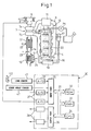
- FIG. 1 shows an overview of a compression ignition type internal combustion engine.
- 1 indicates an engine body, 2 a combustion chamber of each cylinder, 3 an electronically controlled fuel injector for injecting fuel into each combustion chamber 2, 4 an intake manifold, and 5 an exhaust manifold.
- the intake manifold 4 is connected through an intake duct 6 to the outlet of a compressor 7a of an exhaust turbocharger 7.
- the inlet of the compressor 7a is connected to an air cleaner 9 via an intake air amount detector 8.
- a throttle valve 10 driven by a step motor.
- a cooling device (intercooler) 11 for cooling the intake air flowing through the inside of the intake duct 6.
- the engine cooling water is guided into the cooling device 11.
- the engine cooling water cools the intake air.
- the exhaust manifold 5 is connected to the inlet of an exhaust turbine 7b of the exhaust turbocharger 7, while the outlet of the exhaust turbine 7b is connected to the inlet of an SO x trap catalyst 12. Further, the outlet of the SO x trap catalyst 12 is connected through an exhaust pipe 14 to an NOx storing catalyst 13.
- a hydrocarbon supply valve 15 for supplying hydrocarbons comprised of for example fuel into the exhaust gas is arranged in the exhaust manifold 5.
- the exhaust manifold 5 and the intake manifold 4 are interconnected through an exhaust gas recirculation (hereinafter referred to as an "EGR") passage 16.
- the EGR passage 16 is provided with an electronically controlled EGR control valve 17.
- a cooling device 18 for cooling the EGR gas flowing through the inside of the EGR passage 16.
- the engine cooling water is guided into the cooling device 18.
- the engine cooling water cools the EGR gas.
- each fuel injector 3 is connected through a fuel feed tube 19 to a common rail 20.
- This common rail 20 is supplied with fuel from an electronically controlled variable discharge fuel pump 21.
- the fuel supplied into the common rail 20 is supplied through each fuel feed tube 19 to the fuel injector 3.
- An electronic control unit 30 is comprised of a digital computer provided with a read only memory (ROM) 32, a random access memory (RAM) 33, a microprocessor (CPU) 34, an input port 35, and an output port 36 all connected to each other by a bidirectional bus 31.
- the SO x trap catalyst 12 is provided with a temperature sensor 22 for detecting the temperature of the SO x trap catalyst 12.
- a sensor 23 for detecting SO x concentration or HC concentration in the exhaust gas flowing out from the SO x trap catalyst 12 is arranged in the exhaust pipe 14.
- the output signals of the temperature sensor 22 and the sensor 23 are input through corresponding AD converters 37 to the input port 35.
- the NO x storing catalyst 13 is provided with a differential pressure sensor 24 for detecting the differential pressure before and after the NO x storing catalyst 13.
- the output signal of the differential pressure sensor 24 is input through the corresponding AD converter 37 to the input port 35.
- An accelerator pedal 40 has a load sensor 41 generating an output voltage proportional to the amount of depression L of the accelerator pedal 40 connected to it.
- the output voltage of the load sensor 41 is input through a corresponding AD converter 37 to the input port 35.
- the input port 35 has a crank angle sensor 42 generating an output pulse each time the crankshaft turns for example by 15 degrees connected to it.
- the output port 36 is connected through corresponding drive circuits 38 to the fuel injectors 3, step motor for driving the throttle valve 10, hydrocarbon supply valve 15, EGR control valve 17, and fuel pump 21.
- the NO x storing catalyst 13 is carried on a three-dimensional mesh structure monolith carrier or pellet carriers or is carried on a honeycomb structure particulate filter. In this way, the NO x storing catalyst 13 can be carried on various types of carriers, but below, the explanation will be made of the case of carrying the NO x storing catalyst 13 on a particulate filter.
- FIGS. 2(A) and 2(B) show the structure of the particulate filter 13a carrying the NO x storing catalyst 13.
- FIG. 2(A) is a front view of the particulate filter 13a
- FIG. 2(B) is a side sectional view of the particulate filter 13a.
- the particulate filter 1Aa forms a honeycomb structure and is provided with a plurality of exhaust passages 60 and 61 extending in parallel with each other. These exhaust passages are comprised by exhaust gas inflow passages 60 with downstream ends sealed by plugs 62 and exhaust gas outflow passages 61 with upstream ends sealed by plugs 63. Note that the hatched portions in FIG.
- the exhaust gas inflow passages 60 and the exhaust gas outflow passages 61 are arranged alternately through thin wall partitions 64.
- the exhaust gas inflow passages 60 and the exhaust gas outflow passages 61 are arranged so that each exhaust gas inflow passage 60 is surrounded by four exhaust gas outflow passages 61, and each exhaust gas outflow passage 61 is surrounded by four exhaust gas inflow passages 60.
- the particulate filter 13a is formed from a porous material such as for example cordierite. Therefore, the exhaust gas flowing into the exhaust gas inflow passages 60 flows out into the adjoining exhaust gas outflow passages 61 through the surrounding partitions 64 as shown by the arrows in FIG. 2(B) .
- FIG. 3 schematically shows the cross-section of the surface part of this catalyst carrier 45.
- the catalyst carrier 45 carries a precious metal catalyst 46 diffused on its surface.
- the catalyst carrier 45 is formed with a layer of an NO x absorbent 47 on its surface.
- platinum Pt is used as the precious metal catalyst 46.
- the ingredient forming the NO x absorbent 47 for example, at least one element selected from potassium K, sodium Na, cesium Cs, or another alkali metal, barium Ba, calcium Ca, or another alkali earth, lanthanum La, yttrium Y, or another rare earth may be used.
- the NO x absorbent 47 performs an NO x absorption and release action of storing the NO x when the air-fuel ratio of the exhaust gas is lean and releasing the stored NO x when the oxygen concentration in the exhaust gas falls.
- the reaction proceeds in the reverse direction (NO 3 - ⁇ NO 2 ) and therefore the nitric acid ions NO 3 - in the NO x absorbent 47 are released from the NO x absorbent 47 in the form of NO 2 .
- the released NO x is reduced by the unburned hydrocarbons or CO included in the exhaust gas.
- exhaust gas contains SO x , that is, SO 2 .
- SO x that is, SO 2 .
- this SO 2 flows into the NO x storing catalyst 13
- this SO 2 is oxidized at the platinum Pt 46 and becomes SO 3 .
- this SO 3 is absorbed in the NO x absorbent 47 and bonds with the barium oxide BaO while diffusing in the NO x absorbent 47 in the form of sulfate ions SO 4 2- to produce the stable sulfate BaSO 4 .
- the NO x absorbent 47 has a strong basicity, so this sulfate BaSO 4 is stable and hard to decompose. If just making the air-fuel ratio of the exhaust gas rich, the sulfate BaSO 4 will remain without being decomposed. Therefore, in the NO x absorbent 47, the sulfate BaSO 4 will increase along with the elapse of time and therefore the amount of NO x which the NO x absorbent 47 can absorb will fall along with the elapse of time.
- an SO x trap catalyst 12 is arranged upstream of the NO x storing catalyst 13 and this SO x trap catalyst 12 is used to trap the SO x contained in the exhaust gas and thereby prevent SO x from flowing into the NO x storing catalyst 13.
- this SO x trap catalyst 12 will be explained.
- the SO x trap catalyst 12 is comprised of for example a honeycomb structure monolithic catalyst and has a large number of exhaust gas through holes extending straight in the axial direction of the SO x trap catalyst 12.
- FIG. 4(A) schematically shows the cross-section of the surface part of the inside peripheral walls of the exhaust gas through holes, i.e, the substrate in case where the SO x trap catalyst 12 is formed from a honeycomb structure monolithic catalyst in this way.
- a coated layer 51 is formed on the surface of the substrate 50. Further, the coated layer 51 carries a precious metal catalyst 52 diffused on its surface.
- platinum Pt is used as the precious metal catalyst 52.
- the ingredient forming the coated layer 51 for example, at least one element selected from potassium K, sodium Na, cesium Cs, or another alkali metal, barium Ba, calcium Ca, or another alkali earth, lanthanum La, yttrium Y, or another rare earth may be used. That is, the coated layer 51 of the SO x trap catalyst 11 exhibits a strong basicity.
- the SO x contained in the exhaust gas that is, the SO 2
- the platinum 52 as shown in FIG. 4(A)
- the coated layer 51 that is, the SO 2 diffuses in the coated layer 51 in the form of sulfate ions SO 4 2- to form a sulfate.
- the coated layer 51 exhibits a strong basicity. Therefore, part of the SO 2 contained in the exhaust gas is directly trapped in the coated layer 51 as shown in FIG. 4(A) .
- the concentration in the coated layer 51 in FIG. 4(A) shows the concentration of trapped SO x .
- the concentration of SO x in the coated layer 51 is highest near the surface of the coated layer 51 and gradually becomes lower the further deeper. If the SO x concentration near the surface of the coated layer 51 becomes high, the basicity of the surface of the coated layer 51 becomes weaker and the SO x trap capability becomes weaker. Therefore, if the percentage of the SO x trapped by the SO x trap catalyst 12 to the SO x contained in the exhaust gas is referred to as the "SO x trap rate", the SO x trap rate falls along with the basicity of the surface of the coated layer 51 becoming weaker.
- This SO x trap rate is first close to 100 percent, but rapidly falls along with the elapse of time. Therefore, in the embodiment of the present invention, when the SO x trap rate falls below a predetermined rate, temperature raising control is performed to raise the temperature of the SO x trap catalyst 12 under a lean air-fuel ratio of the exhaust gas and thereby restore the SO x trap rate.
- the SO x concentrated near the surface of the coated layer 51 diffuses toward the deep part of the coated layer 51 so that the SO x concentration in the coated layer 51 becomes even. That is, the sulfate produced in the coated layer 51 changes from an unstable state concentrated near the surface of the coated layer 51 to a stable state evenly diffused across the entirety of the inside of the coated layer 51. If the SO x present near the surface of the coated layer 51 diffuses toward the deep part of the coated layer 51, the concentration of SO x near the surface of the coated layer 51 will fall. Therefore, when the temperature raising control of the SO x trap catalyst 12 is completed, the SO x trap rate will be restored.
- the SO x present near the surface of the coated layer 51 can be made to diffuse in the coated layer 51. If raising the temperature of the SO x trap catalyst 12 to about 600°C, the concentration of SO x in the coated layer 51 can be made considerably even. Therefore, at the time of temperature raising control of the SO x trap catalyst 12, it is preferable to raise the temperature of the SO x trap catalyst 12 to about 600°C under a lean air-fuel ratio of the exhaust gas.
- the concentration of the SO x trapped in the SO x trap catalyst 12, as shown in FIG. 4(A) changes toward the interior of the coat layer 51, however, in the SO x trap catalyst 12, the SO x concentration at the surface part of the coat layer 51 further changes according to the position of the SO x trap catalyst 12 in the exhaust gas flow direction.
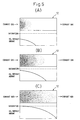
- FIGS. 5(A) to (C) will be explained referring to FIGS. 5(A) to (C) .
- FIGS. 5(A) to (C) the concentration of the SO x trapped at the surface part of the SO x trap catalyst 12, that is, the surface part of the coat layer 51, is shown with shading. Further, in FIGS. 5(A) to (C) , the amount of deposition of SO x deposited at the surface part of the SO x trap catalyst 12, that is, the surface part of the coat layer 51, is shown by a curve. Note that, (A), (B), and (C) of FIG. 5 show a change over time in that order. It is leaned from FIGS. 5(A) to (C) that, along with the passage of time, SO x deposits on the surface part of the coat layer 51 in order from the upstream side and accordingly, the SO x trapping ability is lost in order from the upstream side.
- the SO x trap catalyst 12 soon begins to exhaust SO x .
- sufficient SO x trapping ability still remains at this time at the downstream side of the SO x trap catalyst 12. Accordingly, if able to utilize the SO x trapping ability remaining at this time, the SO x can be trapped by the SO x trap catalyst 12 without the SO x trap catalyst 12 exhausting SO x .
- the amount of hydrocarbons, for example, the fuel, flowing into the SO x trap catalyst 12 is increased so as to form a region in which an air-fuel ratio locally becomes rich in the SO x trap catalyst 12.
- the SO x released from the SO x trap catalyst 12 in this region is trapped in the SO x trap catalyst 12 once again at the downstream side without flowing out from the downstream end of the SO x trap catalyst 12.
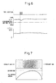
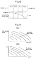
- the excessive hydrocarbons at the upstream end of the SO x trap catalyst 12 will cease being consumed for the SO x reduction, therefore the excessive hydrocarbons will be used to reduce the SO x at the downstream side where the release action of SO x has not progressed so much. In this manner, the release action of the SO x progresses from the upstream side to the downstream side, and the released SO x is trapped once again in the SO x trap catalyst 12 at the downstream side. As a result, as shown in FIG. 7 , the SO x trapping ability at the upstream side of the SO x trap catalyst 12 is restored.
- the amount of increase of the hydrocarbons is set so that, in a region in which an air-fuel ratio becomes locally rich, the SO x released from the SO x trap catalyst 12 is trapped once again in the SO x trap catalyst 12 at the downstream side without flowing out from the downstream end of the SO x trap catalyst 12.
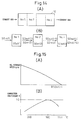
- FIG. 8 shows the regeneration control for this SO x trap rate restoration. As shown in FIG. 8 , under a lean air-fuel ratio of the exhaust gas, fuel is fed from the hydrocarbon feed valve 15 and the temperature T of SO x trap catalyst 12 is raised to about 600°C using the heat of the reaction of the oxidization of this fuel.
- the amount of SO x contained in the exhaust gas that is, the amount of SO x trapped by the SO x trap catalyst 12
- the fuel injection amount is a function of the required torque and the engine speed. Therefore, the amount of SO x trapped by the SO x trap catalyst 12 also becomes a function of the required torque and the engine speed.
- the SO x amount SOXA trapped per unit time in the SO x trap catalyst 12 is stored as a function of the required torque TQ and the engine speed N in the form of a map as shown in FIG. 9(A) in advance in the ROM 32.
- lubrication oil contains a certain ratio of sulfur.
- the amount of lubrication oil burned in a combustion chamber 2 that is, the amount of SO x contained in the exhaust gas and trapped in the SO x trap catalyst 12, becomes a function of the required torque and the engine speed.
- the amount SOXB of SO x contained in the lubrication oil and trapped per unit time in the SO x trap catalyst 12 is stored as a function of the required torque TQ and the engine speed N in the form of a map as shown in FIG. 9(B) in advance in the ROM 32.
- the SO x amount ⁇ SOX trapped in the SO x trap catalyst 12 is calculated.
- the relationship between the SO x amount ⁇ SOX and the predetermined SO x amount SO(n) when the SO x trap catalyst 12 should be regenerated is stored in advance.
- regenerating control of the SO x trap catalyst 12 is performed.
- n shows the number of times of the regenerating control.
- the predetermined amount SO(n) is increased.
- the rate of increase of the predetermined amount SO(n) is reduced the greater the number of times n of regenerating control. That is, the rate of increase of SO(d) to SO(2) is reduced from the rate of increase of SO(2) to SO(1).
- life prolonging treatment of the SO x trap catalyst 12 is performed before performing the regeneration control of the SO x trap catalyst 12.
- the relationship between the SO x amount ⁇ SOX and the predetermined SO x amount SO(m) when life prolonging treatment should be performed on the SO x trap catalyst 12 is stored in advance.
- life prolonging treatment of the SO x trap catalyst 12 is performed. Note that, in FIG. 10 , m shows the number of times of the prolonging treatment.
- step 70 the SO x amounts SOXA and SOXB trapped per unit time are read from FIGS. 9(A) and (B) .
- step 71 the sum of these SOXA and SOXB is added to the SO x amount ⁇ SOX.
- the routine proceeds to step 73.
- the routine proceeds to step 74 where life prolonging control is performed for life prolonging treatment.
- the routine proceeds to step 75 where regeneration control is performed.
- FIG. 12 shows one embodiment of life prolonging control executed at step 74 of FIG. 11 .
- a sensor 23 shown in FIG. 1 an HC concentration sensor detecting the HC concentration in exhaust gas is used. Based on the HC concentration detected by this HC concentration sensor 23, the fuel amount added from the hydrocarbon feed valve 15 is controlled so that HC is not exhausted from the SO x trap catalyst 12 during the life prolonging treatment.
- step 80 the basic fuel addition amount Qo is calculated.
- step 81 it is judged if the output voltage V of the HC concentration sensor 23 has exceeded the predetermined setting VZ, that is, if the HC concentration has exceeded a predetermined setting concentration.
- V>VZ the routine proceeds to step 82, where a constant value is deducted from the correction amount ⁇ Q for the fuel addition amount.
- step 84 the routine proceeds to step 84.
- V ⁇ VZ the routine proceeds to step 83, where a constant value ⁇ is added to the correction amount ⁇ Q, then the routine proceeds to step 84.
- step 84 the correction amount ⁇ Q is added to the basic fuel addition amount Qo.
- the result of the addition is made the fuel addition amount Q.
- step 85 it is judged if the life prolonging treatment has been completed. When the life prolonging treatment has not been completed, the routine proceeds to step 86, where fuel is added, and the routine returns to step 80. In contrast, when the life prolonging treatment has been completed, the routine proceeds to step 87, where the correction amount ⁇ Q is cleared.
- FIG. 13 shows a different embodiment for the treatment routine of the SO x trap catalyst 12 shown in FIG. 11 .
- the sensor 23 shown in FIG. 1 an SO x sensor detecting the SO x concentration in exhaust gas is used, and based on the SO x concentration detected by the SO x sensor 23, life prolonging control and regeneration control are selectively performed.
- step 90 the output V of the SO x sensor 23 is read.
- step 91 it is judged if the output voltage V of the SO x sensor 23 has exceeded the predetermined setting VX, that is if the SO x concentration has exceeded the predetermined setting concentration.
- V>VX that is, when SO x begins to be exhausted from the SO x trap catalyst 12
- the routine proceeds to step 92, where it is judged if it is the first time that V>VX.
- step 94 life prolonging control is performed for life prolonging treatment.
- FIG. 14 to FIG. 20 show several embodiments of creating models of the distribution of deposition of the SO x in the SO x trap catalyst 12 and life prolonging control and regeneration control based on the model deposition distribution of SO x . That is, in these embodiments, as shown in FIG. 14(A) , the SO x trap catalyst 12 is divided into a plurality of catalyst regions No. 1 to No. j along the flow of exhaust gas, and the amount of trapped SO x is calculated in each divided catalyst region No. 1 to No. j. Therefore, first, referring to FIG. 14(B) , the method of calculation of the amount of trapped SO x for each catalyst region No. 1 to No. j will be explained.
- SOin(i) shows the amount of SO x (g/sec) flowing into a catalyst region No. i per unit time
- SOst(i) shows the amount of SO x (g/sec) trapped and deposited in a catalyst region No. i per unit time
- the amount of SO x deposited in a catalyst region No. i is the cumulative value ⁇ SOst(i) of the SOst(i).
- the amount of SO x SOin(l) flowing per unit time in the catalyst region No. 1 positioned furthest upstream may be found from the sum of the SO x trapped amounts SOXA and SOXB shown in FIGS. 9(A) and (B) for example.
- the SO x amount SOst(i) deposited per unit time in each catalyst region No. i is controlled by the SO x storage speed (g/s) to the SO x trap catalyst 12.
- This SO x storage speed falls the more the SO x deposition amount ⁇ SOst(i) increases. Further, this SO x storage speed is a function of the catalyst bed temperature T(i) of the catalyst region No. i.
- the correction coefficient K corresponding to the SO x storage speed shown in FIG. 15(A) is shown in FIG. 15(B) . Accordingly in the embodiment according to the present invention, by multiplying the SO x storage speed shown in FIG. 15(A) with the correction coefficient K shown in FIG. 15(B) , the actual SO x storage speed may be found.
- the SO x amount SOin(i) flowing into the catalyst region No. i is smaller than the aforementioned actual SO x storage speed, all the SO x amount SOin(i) that flows inside is deposited in the catalyst region No. i. If the SO x amount SOin(i) flowing into the catalyst region No. i is larger than the aforementioned actual SO x storage speed, an SO x amount corresponding to the actual SO x storage speed among the SO x amount that flows is deposited in the catalyst region No. i, and the remaining SO x flows into the catalyst region No. (i+1) of the downstream side. Under this manner of thinking, the deposited SO x amount ⁇ SOst(i) of each catalyst region No. i is calculated.
- FIG. 16 shows an example of the results of calculation when dividing the SOx trap catalyst 12 into the four catalyst region No. 1 to No. 4. Note that, the black dots in FIG. 16 show the calculated SOx deposition amounts in the catalyst region No. 1 to No. 4.
- life prolonging treatment of the SO x trap catalyst 12 is performed when the SO x trapped amount of the catalyst region No.4 positioned furthest downstream exceeds the predetermined amount SOZ.
- FIGS. 17(A) and (B) show the SO x release amount at the time of the life prolonging treatment of the SO x trap catalyst 12. Note that, in FIGS. 17(A) and (B) , the curves show equal release amount lines. As shown in FIG. 17(A) , the SO x release amount in each catalyst region No. i increases the more the fuel addition amount increases and increases the more the SO x trapped amount ⁇ SOst(i) increases, and as shown in FIG. 17(B) , the SO x release amount in each catalyst region No. i increases the more the exhaust gas amount, that is, the intake air amount Ga, increases and increases the higher the catalyst bed temperature T(i).
- the change of the SO x deposition amount ⁇ SOst(i) in each catalyst region No. i during the life prolonging treatment is calculated using the relationship shown in FIGS. 17(A) and (B) .
- An example of the calculated results when the life prolonging treatment is completed is shown in FIG. 18 .
- FIG. 19 shows another embodiment.
- the SO x amount SOout(j) flowing out from the SO x trap catalyst 12 is calculated, the SO x concentration in the exhaust gas flowing out from the SO x trap catalyst 12 is detected by the SO x sensor 23, and the SO x deposition amount ⁇ SOst(i) in each catalyst region No. i calculated from the calculated SO x amount and the detected SOx concentration is corrected. That is, if in FIG. 19 , P is the calculated exhaust SO x amount SOout(j) and Q is the exhaust SO x amount determined from the detected SO x concentration, the calculated SO x deposition amount in each catalyst region No. i is raised until the deposition change estimation curve R passing through Q.
- FIG. 20 shows still another embodiment.
- the SO x amount SOout(j) flowing out from the SO x trap catalyst 12 is calculated, the SO x concentration in the exhaust gas flowing out from the SO x trap catalyst 12 is detected by the SO x sensor 23, and the sulfur content of the used fuel is estimated from the calculated SO x amount P and the SO x amount Q determined from the detected SO x concentration. That is, when using the NO x storing catalyst 13, the use of a fuel with a high sulfur content is prohibited, but if a user accidentally uses high sulfur content fuel, in FIG. 20 , as shown by Q, the detected SO x amount is higher in comparison to the calculated SO x amount P.
Landscapes
- Engineering & Computer Science (AREA)
- Chemical & Material Sciences (AREA)
- Combustion & Propulsion (AREA)
- General Engineering & Computer Science (AREA)
- Mechanical Engineering (AREA)
- Analytical Chemistry (AREA)
- Environmental & Geological Engineering (AREA)
- General Chemical & Material Sciences (AREA)
- Oil, Petroleum & Natural Gas (AREA)
- Chemical Kinetics & Catalysis (AREA)
- Biomedical Technology (AREA)
- Health & Medical Sciences (AREA)
- Exhaust Gas After Treatment (AREA)
- Exhaust Gas Treatment By Means Of Catalyst (AREA)
- Combined Controls Of Internal Combustion Engines (AREA)
Claims (8)
- Steuerungsverfahren für eine Abgasreinigungsvorrichtung eines Verbrennungsmotors (1), die einen SOx-Abscheidungskatalysator (12) aufweist, der in einem Abgas enthaltenes SOx abscheiden kann und in einer Motorabgasleitung (14) angeordnet ist, wobei das Verfahren dadurch gekennzeichnet ist, dass,
wenn das auf einer Seite stromauf des SOx-Abscheidungskatalysators abgeschiedene SOx auf eine stromabwärtige Seite bewegt werden soll, um die SOx-Abscheidungsfähigkeit des SOx-Abscheidungskatalysators besser ausnutzen zu können, die Menge der Kohlenwasserstoffe in dem in den SOx-Abscheidungskatalysator einströmenden Abgas erhöht wird, so dass ein Bereich entsteht, in dem ein Kraftstoff-Luft-Verhältnis in dem SOx-Abscheidungskatalysator lokal fett wird,
wobei die Menge der Kohlenwasserstoffe so eingestellt ist, dass das aus dem SOx-Abscheidungskatalysator in dem Bereich freigesetzte SOx in dem SOx-Abscheidungskatalysator auf der stromabwärtigen Seite erneut abgeschieden wird, ohne aus dem stromabwärtigen Ende des SOx-Abscheidungskatalysators auszuströmen, wodurch eine SOx-Abscheidungsrate wiederhergestellt und eine SOx-Abscheidungskatalysator-Lebensdauer verlängert wird. - Verfahren nach Anspruch 1, wobei der SOx-Abscheidungskatalysator eine Eigenschaft aufweist, die das in dem Abgas enthaltene SOx abscheidet, wenn ein Kraftstoff Luft-Verhältnis des in den SOx-Abscheidungskatalysator einströmenden Abgases mager ist, und die das abgeschiedene SOx allmählich auf die Innenseite des NOx-Abscheidungskatalysators diffundiert, wenn die Temperatur des SOx-Abscheidungskatalysators unter einem mageren Kraftstoff-Luft-Verhältnis des Abgases ansteigt, und
wobei, wenn die SOx-Abscheidungsrate erneut abfällt, nachdem die Lebensdauer des SOx-Abscheidungskatalysators verlängert worden ist, eine Temperatur des SOx-Abscheidungskatalysators unter dem mageren Kraftstoff-Luft-Verhältnis des Abgases erhöht wird, um dadurch die SOx-Abscheidungsrate wiederherzustellen. - Verfahren nach Anspruch 1, wobei die in dem SOx-Abscheidungskatalysator abgeschiedene SOx-Menge berechnet wird und die Lebensdauer des SOx-Abscheidungskatalysators verlängert wird, wenn die berechnete SOx-Menge eine vorbestimmte SOx-Menge überschreitet.
- Verfahren nach Anspruch 1, wobei ein SOx-Sensor (23) zum Erfassen einer SOx-Konzentration in dem Abgas, das aus dem SOx-Abscheidungskatalysator ausströmt, vorgesehen ist, und die Lebensdauer des SOx-Abscheidungskatalysator verlängert wird, wenn die erfasste SOx-Konzentration eine vorbestimme Konzentration überschreitet.
- Verfahren nach Anspruch 1, wobei ein Kohlenwasserstoffkonzentrationssensor (23) zum Erfassen einer Kohlenwasserstoffkonzentration in dem aus dem SOx-Abscheidungskatalysator ausströmenden Abgas vorgesehen ist, und die Menge der Kohlenwasserstoffe entsprechend der erfassten Kohlenwasserstoffkonzentration gesteuert wird.
- Verfahren nach Anspruch 1, wobei der SOx-Abscheidungskatalysator in eine Mehrzahl von Katalysatorbereichen entlang einer Abgasströmung unterteilt ist,
wobei die abgeschiedene SOx-Menge eines jeden Katalysatorbereichs berechnet wird, und
wobei die Lebensdauer des SOx-Abscheidungskatalysator verlängert wird, wenn die abgeschiedene SOx-Menge eines Katalysatorbereichs, der am weitesten stromabwärts positioniert ist, eine vorbestimmte Menge überschreitet. - Verfahren nach Anspruch 6, wobei die aus dem SOx-Abscheidungskatalysator ausströmende SOx-Menge berechnet wird,
wobei das Abgasreinigungssystem ferner einen SOx-Sensor zum Erfassen der SOx-Konzentration in dem aus dem SOx-Abscheidungskatalysator ausströmenden Abgas aufweist, und
wobei die abgeschiedene SOx-Menge, die in jedem Katalysatorbereich berechnet wird, anhand der berechneten SOx-Menge und der erfassten SOx-Konzentration korrigiert wird. - Verfahren nach Anspruch 1, wobei die aus dem SOx-Abscheidungskatalysator ausströmende SOx-Menge berechnet wird,
wobei das Abgasreinigungssystem ferner einen SOx-Sensor (23) zum Erfassen der SOx-Konzentration in dem aus dem SOx-Abscheidungskatalysator ausströmenden Abgas aufweist, und
wobei anhand der berechneten SOx-Menge und der erfassten SOx-Konzentration beurteilt wird, ob Kraftstoff mit einem Schwefelgehalt, der höher ist als eine vorbestimmte Konzentration, verwendet wird, und eine Warnung ausgegeben wird, wenn beurteilt wird, dass ein Kraftstoff mit einem Schwefelgehalt, der höher als die vorbestimmte Konzentration ist, verwendet wird.
Applications Claiming Priority (2)
| Application Number | Priority Date | Filing Date | Title |
|---|---|---|---|
| JP2007026637A JP4656065B2 (ja) | 2007-02-06 | 2007-02-06 | 内燃機関の排気浄化装置 |
| PCT/JP2008/051705 WO2008096687A1 (ja) | 2007-02-06 | 2008-01-29 | 内燃機関の排気浄化装置 |
Publications (3)
| Publication Number | Publication Date |
|---|---|
| EP2110526A1 EP2110526A1 (de) | 2009-10-21 |
| EP2110526A4 EP2110526A4 (de) | 2011-02-16 |
| EP2110526B1 true EP2110526B1 (de) | 2012-09-05 |
Family
ID=39681598
Family Applications (1)
| Application Number | Title | Priority Date | Filing Date |
|---|---|---|---|
| EP08704384A Not-in-force EP2110526B1 (de) | 2007-02-06 | 2008-01-29 | Abgasreiniger für einen verbrennungsmotor |
Country Status (5)
| Country | Link |
|---|---|
| US (1) | US8307639B2 (de) |
| EP (1) | EP2110526B1 (de) |
| JP (1) | JP4656065B2 (de) |
| CN (1) | CN101542084B (de) |
| WO (1) | WO2008096687A1 (de) |
Families Citing this family (6)
| Publication number | Priority date | Publication date | Assignee | Title |
|---|---|---|---|---|
| JP4710871B2 (ja) * | 2007-05-15 | 2011-06-29 | トヨタ自動車株式会社 | 内燃機関の排気浄化装置 |
| JP4840274B2 (ja) * | 2007-07-11 | 2011-12-21 | トヨタ自動車株式会社 | 燃料やオイル中の硫黄濃度検出方法 |
| JP5037283B2 (ja) * | 2007-09-26 | 2012-09-26 | 本田技研工業株式会社 | 内燃機関の排気浄化装置 |
| US8621852B2 (en) * | 2009-11-26 | 2014-01-07 | Toyota Jidosha Kabushiki Kaisha | Detector for detecting sulfur components |
| KR101393221B1 (ko) * | 2010-03-23 | 2014-05-08 | 도요타지도샤가부시키가이샤 | 내연 기관의 배기 정화 방법 |
| US8893482B2 (en) * | 2012-03-19 | 2014-11-25 | GM Global Technology Operations LLC | System for determining sulfur storage of aftertreatment devices |
Family Cites Families (15)
| Publication number | Priority date | Publication date | Assignee | Title |
|---|---|---|---|---|
| JP3344040B2 (ja) * | 1993-11-25 | 2002-11-11 | トヨタ自動車株式会社 | 内燃機関の排気浄化装置 |
| EP0892159A3 (de) * | 1997-07-17 | 2000-04-26 | Hitachi, Ltd. | Abgasreiningungsvorrichtung und -Verfahren einer Brennkraftmaschine |
| JP3680650B2 (ja) * | 1999-01-25 | 2005-08-10 | トヨタ自動車株式会社 | 内燃機関の排気浄化装置 |
| US6348177B1 (en) | 1999-02-10 | 2002-02-19 | Southwest Research Institute | Apparatus and method for bypassing sulfur dioxide around an aftertreatment device in an exhaust gas aftertreatment system |
| JP2000300995A (ja) | 1999-04-22 | 2000-10-31 | Toyota Motor Corp | 排ガス浄化用触媒 |
| US20010035006A1 (en) | 2000-02-01 | 2001-11-01 | Danan Dou | Sulfur trap in NOx adsorber systems for enhanced sulfur resistance |
| US6901749B2 (en) * | 2000-08-01 | 2005-06-07 | Honda Giken Kogyo Kabushiki Kaisha | Exhaust emission control system for internal combustion engine |
| JP3855920B2 (ja) * | 2002-11-29 | 2006-12-13 | トヨタ自動車株式会社 | 内燃機関の排気浄化装置 |
| JP4020054B2 (ja) * | 2003-09-24 | 2007-12-12 | トヨタ自動車株式会社 | 内燃機関の排気浄化システム |
| JP3938136B2 (ja) * | 2003-10-29 | 2007-06-27 | トヨタ自動車株式会社 | 圧縮着火式内燃機関の排気浄化装置 |
| US20050223698A1 (en) * | 2004-03-31 | 2005-10-13 | Mitsubishi Fuso Truck And Bus Corporation | Exhaust gas cleaning device |
| US7111451B2 (en) * | 2004-09-16 | 2006-09-26 | Delphi Technologies, Inc. | NOx adsorber diagnostics and automotive exhaust control system utilizing the same |
| JP3969423B2 (ja) | 2005-01-06 | 2007-09-05 | トヨタ自動車株式会社 | 内燃機関の排気浄化装置 |
| JP4100412B2 (ja) * | 2005-04-12 | 2008-06-11 | トヨタ自動車株式会社 | 圧縮着火式内燃機関の排気浄化装置 |
| JP5037283B2 (ja) * | 2007-09-26 | 2012-09-26 | 本田技研工業株式会社 | 内燃機関の排気浄化装置 |
-
2007
- 2007-02-06 JP JP2007026637A patent/JP4656065B2/ja not_active Expired - Fee Related
-
2008
- 2008-01-29 CN CN200880000727.2A patent/CN101542084B/zh not_active Expired - Fee Related
- 2008-01-29 US US12/308,768 patent/US8307639B2/en not_active Expired - Fee Related
- 2008-01-29 EP EP08704384A patent/EP2110526B1/de not_active Not-in-force
- 2008-01-29 WO PCT/JP2008/051705 patent/WO2008096687A1/ja not_active Ceased
Also Published As
| Publication number | Publication date |
|---|---|
| CN101542084B (zh) | 2011-12-14 |
| EP2110526A1 (de) | 2009-10-21 |
| JP2008190445A (ja) | 2008-08-21 |
| WO2008096687A1 (ja) | 2008-08-14 |
| JP4656065B2 (ja) | 2011-03-23 |
| EP2110526A4 (de) | 2011-02-16 |
| US20090308053A1 (en) | 2009-12-17 |
| CN101542084A (zh) | 2009-09-23 |
| US8307639B2 (en) | 2012-11-13 |
Similar Documents
| Publication | Publication Date | Title |
|---|---|---|
| US7181904B2 (en) | Exhaust purification device of compression ignition type internal combustion engine | |
| EP1843016B1 (de) | Verbrennungsmotor | |
| JP2009114879A (ja) | 内燃機関の排気浄化装置 | |
| EP1760282B1 (de) | Abgasreiniger für einen kompressionsgezündeten verbrennungsmotor | |
| EP2110526B1 (de) | Abgasreiniger für einen verbrennungsmotor | |
| US8051647B2 (en) | Exhaust purification device of internal combustion engine | |
| US7891175B2 (en) | Exhaust purification device of compression ignition type internal combustion engine | |
| US8136346B2 (en) | Internal combustion engine | |
| US20090031705A1 (en) | Exhaust Gas Purification Device of Compression Ignition Type Internal Combustion Engine | |
| US8033100B2 (en) | Exhaust purification device of compression ignition type internal combustion engine |
Legal Events
| Date | Code | Title | Description |
|---|---|---|---|
| PUAI | Public reference made under article 153(3) epc to a published international application that has entered the european phase |
Free format text: ORIGINAL CODE: 0009012 |
|
| 17P | Request for examination filed |
Effective date: 20090907 |
|
| AK | Designated contracting states |
Kind code of ref document: A1 Designated state(s): AT BE BG CH CY CZ DE DK EE ES FI FR GB GR HR HU IE IS IT LI LT LU LV MC MT NL NO PL PT RO SE SI SK TR |
|
| DAX | Request for extension of the european patent (deleted) | ||
| A4 | Supplementary search report drawn up and despatched |
Effective date: 20110117 |
|
| GRAP | Despatch of communication of intention to grant a patent |
Free format text: ORIGINAL CODE: EPIDOSNIGR1 |
|
| GRAS | Grant fee paid |
Free format text: ORIGINAL CODE: EPIDOSNIGR3 |
|
| GRAA | (expected) grant |
Free format text: ORIGINAL CODE: 0009210 |
|
| AK | Designated contracting states |
Kind code of ref document: B1 Designated state(s): AT BE BG CH CY CZ DE DK EE ES FI FR GB GR HR HU IE IS IT LI LT LU LV MC MT NL NO PL PT RO SE SI SK TR |
|
| REG | Reference to a national code |
Ref country code: GB Ref legal event code: FG4D |
|
| REG | Reference to a national code |
Ref country code: CH Ref legal event code: EP |
|
| REG | Reference to a national code |
Ref country code: AT Ref legal event code: REF Ref document number: 574242 Country of ref document: AT Kind code of ref document: T Effective date: 20120915 |
|
| REG | Reference to a national code |
Ref country code: IE Ref legal event code: FG4D |
|
| REG | Reference to a national code |
Ref country code: DE Ref legal event code: R096 Ref document number: 602008018548 Country of ref document: DE Effective date: 20121031 |
|
| REG | Reference to a national code |
Ref country code: AT Ref legal event code: MK05 Ref document number: 574242 Country of ref document: AT Kind code of ref document: T Effective date: 20120905 |
|
| REG | Reference to a national code |
Ref country code: NL Ref legal event code: VDEP Effective date: 20120905 |
|
| PG25 | Lapsed in a contracting state [announced via postgrant information from national office to epo] |
Ref country code: NO Free format text: LAPSE BECAUSE OF FAILURE TO SUBMIT A TRANSLATION OF THE DESCRIPTION OR TO PAY THE FEE WITHIN THE PRESCRIBED TIME-LIMIT Effective date: 20121205 Ref country code: LT Free format text: LAPSE BECAUSE OF FAILURE TO SUBMIT A TRANSLATION OF THE DESCRIPTION OR TO PAY THE FEE WITHIN THE PRESCRIBED TIME-LIMIT Effective date: 20120905 Ref country code: HR Free format text: LAPSE BECAUSE OF FAILURE TO SUBMIT A TRANSLATION OF THE DESCRIPTION OR TO PAY THE FEE WITHIN THE PRESCRIBED TIME-LIMIT Effective date: 20120905 Ref country code: FI Free format text: LAPSE BECAUSE OF FAILURE TO SUBMIT A TRANSLATION OF THE DESCRIPTION OR TO PAY THE FEE WITHIN THE PRESCRIBED TIME-LIMIT Effective date: 20120905 Ref country code: AT Free format text: LAPSE BECAUSE OF FAILURE TO SUBMIT A TRANSLATION OF THE DESCRIPTION OR TO PAY THE FEE WITHIN THE PRESCRIBED TIME-LIMIT Effective date: 20120905 |
|
| RAP2 | Party data changed (patent owner data changed or rights of a patent transferred) |
Owner name: TOYOTA JIDOSHA KABUSHIKI KAISHA |
|
| REG | Reference to a national code |
Ref country code: LT Ref legal event code: MG4D Effective date: 20120905 |
|
| PG25 | Lapsed in a contracting state [announced via postgrant information from national office to epo] |
Ref country code: GR Free format text: LAPSE BECAUSE OF FAILURE TO SUBMIT A TRANSLATION OF THE DESCRIPTION OR TO PAY THE FEE WITHIN THE PRESCRIBED TIME-LIMIT Effective date: 20121206 Ref country code: SE Free format text: LAPSE BECAUSE OF FAILURE TO SUBMIT A TRANSLATION OF THE DESCRIPTION OR TO PAY THE FEE WITHIN THE PRESCRIBED TIME-LIMIT Effective date: 20120905 Ref country code: SI Free format text: LAPSE BECAUSE OF FAILURE TO SUBMIT A TRANSLATION OF THE DESCRIPTION OR TO PAY THE FEE WITHIN THE PRESCRIBED TIME-LIMIT Effective date: 20120905 Ref country code: LV Free format text: LAPSE BECAUSE OF FAILURE TO SUBMIT A TRANSLATION OF THE DESCRIPTION OR TO PAY THE FEE WITHIN THE PRESCRIBED TIME-LIMIT Effective date: 20120905 |
|
| PG25 | Lapsed in a contracting state [announced via postgrant information from national office to epo] |
Ref country code: ES Free format text: LAPSE BECAUSE OF FAILURE TO SUBMIT A TRANSLATION OF THE DESCRIPTION OR TO PAY THE FEE WITHIN THE PRESCRIBED TIME-LIMIT Effective date: 20121216 Ref country code: CZ Free format text: LAPSE BECAUSE OF FAILURE TO SUBMIT A TRANSLATION OF THE DESCRIPTION OR TO PAY THE FEE WITHIN THE PRESCRIBED TIME-LIMIT Effective date: 20120905 Ref country code: BE Free format text: LAPSE BECAUSE OF FAILURE TO SUBMIT A TRANSLATION OF THE DESCRIPTION OR TO PAY THE FEE WITHIN THE PRESCRIBED TIME-LIMIT Effective date: 20120905 Ref country code: RO Free format text: LAPSE BECAUSE OF FAILURE TO SUBMIT A TRANSLATION OF THE DESCRIPTION OR TO PAY THE FEE WITHIN THE PRESCRIBED TIME-LIMIT Effective date: 20120905 Ref country code: IS Free format text: LAPSE BECAUSE OF FAILURE TO SUBMIT A TRANSLATION OF THE DESCRIPTION OR TO PAY THE FEE WITHIN THE PRESCRIBED TIME-LIMIT Effective date: 20130105 Ref country code: NL Free format text: LAPSE BECAUSE OF FAILURE TO SUBMIT A TRANSLATION OF THE DESCRIPTION OR TO PAY THE FEE WITHIN THE PRESCRIBED TIME-LIMIT Effective date: 20120905 Ref country code: EE Free format text: LAPSE BECAUSE OF FAILURE TO SUBMIT A TRANSLATION OF THE DESCRIPTION OR TO PAY THE FEE WITHIN THE PRESCRIBED TIME-LIMIT Effective date: 20120905 |
|
| PG25 | Lapsed in a contracting state [announced via postgrant information from national office to epo] |
Ref country code: CY Free format text: LAPSE BECAUSE OF FAILURE TO SUBMIT A TRANSLATION OF THE DESCRIPTION OR TO PAY THE FEE WITHIN THE PRESCRIBED TIME-LIMIT Effective date: 20120905 Ref country code: SK Free format text: LAPSE BECAUSE OF FAILURE TO SUBMIT A TRANSLATION OF THE DESCRIPTION OR TO PAY THE FEE WITHIN THE PRESCRIBED TIME-LIMIT Effective date: 20120905 Ref country code: PL Free format text: LAPSE BECAUSE OF FAILURE TO SUBMIT A TRANSLATION OF THE DESCRIPTION OR TO PAY THE FEE WITHIN THE PRESCRIBED TIME-LIMIT Effective date: 20120905 Ref country code: PT Free format text: LAPSE BECAUSE OF FAILURE TO SUBMIT A TRANSLATION OF THE DESCRIPTION OR TO PAY THE FEE WITHIN THE PRESCRIBED TIME-LIMIT Effective date: 20130107 |
|
| PLBE | No opposition filed within time limit |
Free format text: ORIGINAL CODE: 0009261 |
|
| STAA | Information on the status of an ep patent application or granted ep patent |
Free format text: STATUS: NO OPPOSITION FILED WITHIN TIME LIMIT |
|
| PG25 | Lapsed in a contracting state [announced via postgrant information from national office to epo] |
Ref country code: BG Free format text: LAPSE BECAUSE OF FAILURE TO SUBMIT A TRANSLATION OF THE DESCRIPTION OR TO PAY THE FEE WITHIN THE PRESCRIBED TIME-LIMIT Effective date: 20121205 Ref country code: DK Free format text: LAPSE BECAUSE OF FAILURE TO SUBMIT A TRANSLATION OF THE DESCRIPTION OR TO PAY THE FEE WITHIN THE PRESCRIBED TIME-LIMIT Effective date: 20120905 |
|
| 26N | No opposition filed |
Effective date: 20130606 |
|
| PG25 | Lapsed in a contracting state [announced via postgrant information from national office to epo] |
Ref country code: MC Free format text: LAPSE BECAUSE OF NON-PAYMENT OF DUE FEES Effective date: 20130131 Ref country code: IT Free format text: LAPSE BECAUSE OF FAILURE TO SUBMIT A TRANSLATION OF THE DESCRIPTION OR TO PAY THE FEE WITHIN THE PRESCRIBED TIME-LIMIT Effective date: 20120905 |
|
| REG | Reference to a national code |
Ref country code: CH Ref legal event code: PL |
|
| GBPC | Gb: european patent ceased through non-payment of renewal fee |
Effective date: 20130129 |
|
| REG | Reference to a national code |
Ref country code: DE Ref legal event code: R097 Ref document number: 602008018548 Country of ref document: DE Effective date: 20130606 |
|
| REG | Reference to a national code |
Ref country code: IE Ref legal event code: MM4A |
|
| PG25 | Lapsed in a contracting state [announced via postgrant information from national office to epo] |
Ref country code: LI Free format text: LAPSE BECAUSE OF NON-PAYMENT OF DUE FEES Effective date: 20130131 Ref country code: CH Free format text: LAPSE BECAUSE OF NON-PAYMENT OF DUE FEES Effective date: 20130131 |
|
| REG | Reference to a national code |
Ref country code: DE Ref legal event code: R084 Ref document number: 602008018548 Country of ref document: DE Effective date: 20130919 |
|
| PG25 | Lapsed in a contracting state [announced via postgrant information from national office to epo] |
Ref country code: GB Free format text: LAPSE BECAUSE OF NON-PAYMENT OF DUE FEES Effective date: 20130129 |
|
| PG25 | Lapsed in a contracting state [announced via postgrant information from national office to epo] |
Ref country code: IE Free format text: LAPSE BECAUSE OF NON-PAYMENT OF DUE FEES Effective date: 20130129 |
|
| PG25 | Lapsed in a contracting state [announced via postgrant information from national office to epo] |
Ref country code: MT Free format text: LAPSE BECAUSE OF FAILURE TO SUBMIT A TRANSLATION OF THE DESCRIPTION OR TO PAY THE FEE WITHIN THE PRESCRIBED TIME-LIMIT Effective date: 20120905 |
|
| REG | Reference to a national code |
Ref country code: FR Ref legal event code: PLFP Year of fee payment: 8 |
|
| PGFP | Annual fee paid to national office [announced via postgrant information from national office to epo] |
Ref country code: DE Payment date: 20150120 Year of fee payment: 8 |
|
| PGFP | Annual fee paid to national office [announced via postgrant information from national office to epo] |
Ref country code: FR Payment date: 20150108 Year of fee payment: 8 |
|
| PG25 | Lapsed in a contracting state [announced via postgrant information from national office to epo] |
Ref country code: TR Free format text: LAPSE BECAUSE OF FAILURE TO SUBMIT A TRANSLATION OF THE DESCRIPTION OR TO PAY THE FEE WITHIN THE PRESCRIBED TIME-LIMIT Effective date: 20120905 |
|
| PG25 | Lapsed in a contracting state [announced via postgrant information from national office to epo] |
Ref country code: LU Free format text: LAPSE BECAUSE OF NON-PAYMENT OF DUE FEES Effective date: 20130129 Ref country code: HU Free format text: LAPSE BECAUSE OF FAILURE TO SUBMIT A TRANSLATION OF THE DESCRIPTION OR TO PAY THE FEE WITHIN THE PRESCRIBED TIME-LIMIT; INVALID AB INITIO Effective date: 20080129 |
|
| REG | Reference to a national code |
Ref country code: DE Ref legal event code: R119 Ref document number: 602008018548 Country of ref document: DE |
|
| REG | Reference to a national code |
Ref country code: FR Ref legal event code: ST Effective date: 20160930 |
|
| PG25 | Lapsed in a contracting state [announced via postgrant information from national office to epo] |
Ref country code: DE Free format text: LAPSE BECAUSE OF NON-PAYMENT OF DUE FEES Effective date: 20160802 |
|
| PG25 | Lapsed in a contracting state [announced via postgrant information from national office to epo] |
Ref country code: FR Free format text: LAPSE BECAUSE OF NON-PAYMENT OF DUE FEES Effective date: 20160201 |