EP2110562A1 - Agencement de vannes - Google Patents
Agencement de vannes Download PDFInfo
- Publication number
- EP2110562A1 EP2110562A1 EP08007380A EP08007380A EP2110562A1 EP 2110562 A1 EP2110562 A1 EP 2110562A1 EP 08007380 A EP08007380 A EP 08007380A EP 08007380 A EP08007380 A EP 08007380A EP 2110562 A1 EP2110562 A1 EP 2110562A1
- Authority
- EP
- European Patent Office
- Prior art keywords
- valve
- unit
- arrangement according
- interface
- electrical
- Prior art date
- Legal status (The legal status is an assumption and is not a legal conclusion. Google has not performed a legal analysis and makes no representation as to the accuracy of the status listed.)
- Granted
Links
Images

Classifications
-
- F—MECHANICAL ENGINEERING; LIGHTING; HEATING; WEAPONS; BLASTING
- F15—FLUID-PRESSURE ACTUATORS; HYDRAULICS OR PNEUMATICS IN GENERAL
- F15B—SYSTEMS ACTING BY MEANS OF FLUIDS IN GENERAL; FLUID-PRESSURE ACTUATORS, e.g. SERVOMOTORS; DETAILS OF FLUID-PRESSURE SYSTEMS, NOT OTHERWISE PROVIDED FOR
- F15B13/00—Details of servomotor systems ; Valves for servomotor systems
- F15B13/02—Fluid distribution or supply devices characterised by their adaptation to the control of servomotors
- F15B13/06—Fluid distribution or supply devices characterised by their adaptation to the control of servomotors for use with two or more servomotors
- F15B13/08—Assemblies of units, each for the control of a single servomotor only
- F15B13/0803—Modular units
- F15B13/0846—Electrical details
- F15B13/0857—Electrical connecting means, e.g. plugs, sockets
-
- H—ELECTRICITY
- H01—ELECTRIC ELEMENTS
- H01R—ELECTRICALLY-CONDUCTIVE CONNECTIONS; STRUCTURAL ASSOCIATIONS OF A PLURALITY OF MUTUALLY-INSULATED ELECTRICAL CONNECTING ELEMENTS; COUPLING DEVICES; CURRENT COLLECTORS
- H01R31/00—Coupling parts supported only by co-operation with counterpart
- H01R31/06—Intermediate parts for linking two coupling parts, e.g. adapter
-
- F—MECHANICAL ENGINEERING; LIGHTING; HEATING; WEAPONS; BLASTING
- F15—FLUID-PRESSURE ACTUATORS; HYDRAULICS OR PNEUMATICS IN GENERAL
- F15B—SYSTEMS ACTING BY MEANS OF FLUIDS IN GENERAL; FLUID-PRESSURE ACTUATORS, e.g. SERVOMOTORS; DETAILS OF FLUID-PRESSURE SYSTEMS, NOT OTHERWISE PROVIDED FOR
- F15B13/00—Details of servomotor systems ; Valves for servomotor systems
- F15B2013/002—Modular valves, i.e. consisting of an assembly of interchangeable components
- F15B2013/006—Modular components with multiple uses, e.g. kits for either normally-open or normally-closed valves, interchangeable or reprogrammable manifolds
Definitions
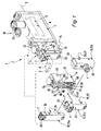
- the invention relates to a valve arrangement comprising at least one valve unit having an electrically actuatable valve drive and carrying an electrical connection unit designed to connect an electrical cable to which an electrical plug interface accessible from the outside for detachably connecting a connector plug attached to the cable is arranged , which is in electrical communication with the valve drive.
- the usable for attaching the terminal units second mechanical interface extends to the valve unit expediently uninterrupted both on the valve drive and on the base body away. Thus, a very large footprint is available for attachment of a relatively large outline terminal unit.
- valve unit 14 is itself an assembly consisting of two held together by suitable fastening means 18 components in the form of an electrically actuated
- the only roughly indicated valve channels 24 open to the back 16 and communicate with running in the main valve 3 channels in communication, via which the fluidic input signal is supplied and via the fluidic output signal to the main valve member 12 is headed.
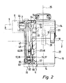
- valve drive 22 and the base body 23 are attached to each other in the axial direction of a perpendicular to the longitudinal axis 2 vertical axis 25. Based on a common orientation of the installed valve assembly 1, the valve drive 22 is down and the base 23 sits up.
- the valve drive 22 has arranged on the front side 17 of the valve unit 14 second electrical interface means 27, which are expediently designed in the form of two projecting forward, for example, formed as a contact lugs or pins contact elements 46. Via the second electrical interface means 27, the valve drive 22 receives the electrical signals required for its actuation.
- the valve drive 22 is an electromagnet whose movable armature is drivingly connected to a valve member 28 or forms this directly.
- the valve member 28 cooperates with a valve seat 32, in particular formed on or in the base body 23, in order, depending on the position, to pass a fluidic output signal to the main valve 3 or shut off it.
- the valve assembly 1 includes a plurality of terminal units 15, wherein in FIG. 1 three pieces of such terminal units 15 are shown. All these connection units 15th are equipped on their rear side 37 with first mechanical interfaces 35, which are designed such that they can be mounted on the second mechanical interface 36 on the valve unit 14 as an alternative to one another.
- the user of the valve arrangement 1 thus has the possibility of selecting from a supply of different electrical connection units 15 the connection unit 15 which is particularly suitable for the particular application and growing it on the valve unit 14.
- the remaining terminal units 14 can then be used for other valve assemblies 1 or are available for replacement, if later there is a need to replace the currently mounted valve unit 14 by another valve unit 14.
- the connector interface 7 of the first terminal unit 15a is oriented laterally transversely to the longitudinal axis 2 and in particular at right angles thereto, while in the other two terminal units 15b, 15c in the axial direction of the longitudinal axis 2 of the valve unit 14 points away towards the front.
- the terminal unit 15 In mounted on the valve unit 14 state of a connector plug 6 is the electrical connector interface 7 with the valve drive 22 in electrical connection.
- the terminal unit 15 includes in the region of its first mechanical interface 35 first electrical interface means 26, which are permanently connected via an internal electrical conductor of the terminal unit 15 to the connector interface 17 associated electrical contact means 44, and to the other releasably connected to the second electrical interface means 27 of the valve unit 14 are in electrically conductive engagement.
- All terminal units 15 are expediently equipped with first electrical interface means 26 in mutually coincident manner.
- the arrangement is such that when a terminal unit 15 is attached to the valve unit 14, the first electrical interface means 26 automatically come into contact with the second electrical interface means 27 and that contact engagement upon removal of the terminal unit 15 and thus upon separation of the first and second mechanical interfaces 35, 36 is also automatically separated from each other.
- Automatic means here that except the process of mechanical mounting and dismounting of a terminal unit 15 no specific intervention is required to the electrical Interface means to connect or disconnect from each other.
- the first and second mechanical interface 35, 36 are equipped with holding means 52 which serve for releasably securing the terminal unit 15 to the valve unit 14.
- These holding means 52 are formed in an advantageous manner so that the terminal units 15 attach without the aid of a tool to the valve unit 14 and can be solved by this again. A conversion of the valve unit 14 with respect to its terminal unit 15 can thus be carried out very quickly.
- the second holding means group 52b includes in the region of the underside of the terminal unit 15 arranged second hook means 55, the hook portion opposite to the hook portion of the first hook means 53 projects down and opposite to which arranged on the front side of the valve unit 14 second recess means 56 which are open at the top.
- the first and second recess means 54, 56 are each formed in a wall section of the valve unit 14 extending in the axial direction of the longitudinal axis 2, which can engage under the hook means 53, 55.
- the removal of the terminal unit 15 is done in a comparatively simple manner.
- upstream release slide 63 is slidably mounted in the axial direction of the longitudinal axis 2. He can also join in the pivotal movement of the second hook means 55. To release the latching connection, it is manually displaced in the direction of the valve unit 14, wherein it slides upwards on the inclined surface 62 and in this case lifts the second hooking means 55 out of the second recessing means 56.
- the terminal unit 15 can be reversed as in FIG. 4 shown in an inclined position pivoted away from the valve unit 14 and then removed from their engagement with the first recess means 54.
- the first hook means 53 are in the embodiment part of an inserted into the hood-shaped housing part 48 closure plate 64, between which and the front wall of the hood-shaped housing part 48, the circuit board 47 is held.
- the closure plate 64 is provided with openings which allow the passage of the first and / or second electrical interface means 26, 27.
- lateral locking means 65 the closure plate 64 is expediently releasably latched to the peripheral side wall of the hood-shaped housing part 48.
Landscapes
- Engineering & Computer Science (AREA)
- Physics & Mathematics (AREA)
- Fluid Mechanics (AREA)
- Mechanical Engineering (AREA)
- General Engineering & Computer Science (AREA)
- Valve Housings (AREA)
- Connections Arranged To Contact A Plurality Of Conductors (AREA)
- Connector Housings Or Holding Contact Members (AREA)
- Details Of Connecting Devices For Male And Female Coupling (AREA)
- Magnetically Actuated Valves (AREA)
- Lift Valve (AREA)
Priority Applications (3)
| Application Number | Priority Date | Filing Date | Title |
|---|---|---|---|
| AT08007380T ATE508284T1 (de) | 2008-04-15 | 2008-04-15 | Ventilanordnung |
| EP08007380A EP2110562B1 (fr) | 2008-04-15 | 2008-04-15 | Agencement de vannes |
| DE502008003418T DE502008003418D1 (de) | 2008-04-15 | 2008-04-15 | Ventilanordnung |
Applications Claiming Priority (1)
| Application Number | Priority Date | Filing Date | Title |
|---|---|---|---|
| EP08007380A EP2110562B1 (fr) | 2008-04-15 | 2008-04-15 | Agencement de vannes |
Publications (2)
| Publication Number | Publication Date |
|---|---|
| EP2110562A1 true EP2110562A1 (fr) | 2009-10-21 |
| EP2110562B1 EP2110562B1 (fr) | 2011-05-04 |
Family
ID=39734974
Family Applications (1)
| Application Number | Title | Priority Date | Filing Date |
|---|---|---|---|
| EP08007380A Active EP2110562B1 (fr) | 2008-04-15 | 2008-04-15 | Agencement de vannes |
Country Status (3)
| Country | Link |
|---|---|
| EP (1) | EP2110562B1 (fr) |
| AT (1) | ATE508284T1 (fr) |
| DE (1) | DE502008003418D1 (fr) |
Cited By (3)
| Publication number | Priority date | Publication date | Assignee | Title |
|---|---|---|---|---|
| FR2995371A1 (fr) * | 2012-09-12 | 2014-03-14 | Asco Joucomatic Sa | Distributeur electropneumatique. |
| CN103939652A (zh) * | 2012-12-13 | 2014-07-23 | 费斯托股份有限两合公司 | 阀装置 |
| DE102023136228A1 (de) * | 2023-12-21 | 2025-06-26 | Festo Se & Co. Kg | Elektromechanische Anschlussvorrichtung und damit ausgestattetes Wegeventil |
Families Citing this family (2)
| Publication number | Priority date | Publication date | Assignee | Title |
|---|---|---|---|---|
| DE102021112003A1 (de) | 2021-05-07 | 2022-11-10 | ECO Holding 1 GmbH | Antriebsvorrichtung für ein Ventil |
| EP4456094A1 (fr) * | 2023-04-26 | 2024-10-30 | KNORR-BREMSE Systeme für Nutzfahrzeuge GmbH | Ensemble solénoïde et son procédé de fabrication |
Citations (5)
| Publication number | Priority date | Publication date | Assignee | Title |
|---|---|---|---|---|
| DE3605950A1 (de) * | 1985-03-23 | 1986-10-02 | Shoketsu Kinzoku Kogyo K.K., Tokio/Tokyo | Stromanschlussanordnung fuer elektromagnetventile |
| US4736177A (en) | 1985-10-31 | 1988-04-05 | Automatic Switch Company | Solenoid actuator with electrical connection modules |
| DE29507119U1 (de) * | 1995-04-27 | 1995-07-20 | Bürkert Werke GmbH & Co., 74653 Ingelfingen | Modularer elektrischer Teil für einen Ventilblock |
| DE29608532U1 (de) * | 1996-05-03 | 1996-08-01 | Mannesmann AG, 40213 Düsseldorf | Kontaktiereinrichtung für Mehrwege-Magnetventile |
| EP1586777A1 (fr) * | 2004-04-16 | 2005-10-19 | FESTO AG & Co | Kit pour vanne proportionnelle et vanne assemblée avec un tel kit. |
-
2008
- 2008-04-15 EP EP08007380A patent/EP2110562B1/fr active Active
- 2008-04-15 AT AT08007380T patent/ATE508284T1/de active
- 2008-04-15 DE DE502008003418T patent/DE502008003418D1/de active Active
Patent Citations (5)
| Publication number | Priority date | Publication date | Assignee | Title |
|---|---|---|---|---|
| DE3605950A1 (de) * | 1985-03-23 | 1986-10-02 | Shoketsu Kinzoku Kogyo K.K., Tokio/Tokyo | Stromanschlussanordnung fuer elektromagnetventile |
| US4736177A (en) | 1985-10-31 | 1988-04-05 | Automatic Switch Company | Solenoid actuator with electrical connection modules |
| DE29507119U1 (de) * | 1995-04-27 | 1995-07-20 | Bürkert Werke GmbH & Co., 74653 Ingelfingen | Modularer elektrischer Teil für einen Ventilblock |
| DE29608532U1 (de) * | 1996-05-03 | 1996-08-01 | Mannesmann AG, 40213 Düsseldorf | Kontaktiereinrichtung für Mehrwege-Magnetventile |
| EP1586777A1 (fr) * | 2004-04-16 | 2005-10-19 | FESTO AG & Co | Kit pour vanne proportionnelle et vanne assemblée avec un tel kit. |
Cited By (4)
| Publication number | Priority date | Publication date | Assignee | Title |
|---|---|---|---|---|
| FR2995371A1 (fr) * | 2012-09-12 | 2014-03-14 | Asco Joucomatic Sa | Distributeur electropneumatique. |
| EP2708758A1 (fr) | 2012-09-12 | 2014-03-19 | Asco Joucomatic SA | Distributeur électropneumatique |
| CN103939652A (zh) * | 2012-12-13 | 2014-07-23 | 费斯托股份有限两合公司 | 阀装置 |
| DE102023136228A1 (de) * | 2023-12-21 | 2025-06-26 | Festo Se & Co. Kg | Elektromechanische Anschlussvorrichtung und damit ausgestattetes Wegeventil |
Also Published As
| Publication number | Publication date |
|---|---|
| ATE508284T1 (de) | 2011-05-15 |
| EP2110562B1 (fr) | 2011-05-04 |
| DE502008003418D1 (de) | 2011-06-16 |
Similar Documents
| Publication | Publication Date | Title |
|---|---|---|
| EP2137415B1 (fr) | Appareil de commande modulaire, en particulier du type électrofluidique | |
| DE69608868T2 (de) | Befestigungsvorrichtung für Verbinders eines Magnetventils | |
| DE4004834C2 (de) | Ventilbaugruppe | |
| DE69838570T2 (de) | Verbinder mit Kupplungserkennungsmitteln | |
| DE2813562C2 (de) | Verteileranlage für elektropneumatische Systeme | |
| DE60036745T2 (de) | Magnetventilblock mit seriellem Datenbus | |
| DE69420122T2 (de) | Magnetventilbaugruppe | |
| DE102005015200A1 (de) | Kopplungsventil | |
| DE3431163A1 (de) | Schalteinheit | |
| DE19748530B9 (de) | Modulares Automatisierungsgerät und Baugruppe eines modularen Automatisierungsgerätes | |
| DE102011100327B3 (de) | Fluidtechnische Baugruppe | |
| EP2110562B1 (fr) | Agencement de vannes | |
| DE202018004944U1 (de) | Reihensteckklemme | |
| DE102016121347B4 (de) | Elektronikmodul für I/O-Modulsystem | |
| WO2015169691A1 (fr) | Barrette de connexion pour un appareil électronique | |
| WO1998041766A1 (fr) | Base de montage en forme de plaque | |
| CH618539A5 (fr) | ||
| EP2273626A1 (fr) | Dispositif de sécurisation | |
| DE102017220621A1 (de) | Verbinder | |
| EP1464843B1 (fr) | Dispositif de commande | |
| EP2255094B1 (fr) | Batterie de distributeurs | |
| EP1180602B1 (fr) | Aménagement de soupapes de commandes, et soupape pour celle-çi | |
| DE102008033859A1 (de) | Aktuatoreinheit mit separater Regelungseinheit | |
| EP2781811B1 (fr) | Dispositif d'aération | |
| DE102010032990B4 (de) | Fluidverteileranordnung |
Legal Events
| Date | Code | Title | Description |
|---|---|---|---|
| PUAI | Public reference made under article 153(3) epc to a published international application that has entered the european phase |
Free format text: ORIGINAL CODE: 0009012 |
|
| AK | Designated contracting states |
Kind code of ref document: A1 Designated state(s): AT BE BG CH CY CZ DE DK EE ES FI FR GB GR HR HU IE IS IT LI LT LU LV MC MT NL NO PL PT RO SE SI SK TR |
|
| AX | Request for extension of the european patent |
Extension state: AL BA MK RS |
|
| 17P | Request for examination filed |
Effective date: 20091015 |
|
| 17Q | First examination report despatched |
Effective date: 20091112 |
|
| AKX | Designation fees paid |
Designated state(s): AT BE BG CH CY CZ DE DK EE ES FI FR GB GR HR HU IE IS IT LI LT LU LV MC MT NL NO PL PT RO SE SI SK TR |
|
| GRAP | Despatch of communication of intention to grant a patent |
Free format text: ORIGINAL CODE: EPIDOSNIGR1 |
|
| GRAS | Grant fee paid |
Free format text: ORIGINAL CODE: EPIDOSNIGR3 |
|
| GRAA | (expected) grant |
Free format text: ORIGINAL CODE: 0009210 |
|
| AK | Designated contracting states |
Kind code of ref document: B1 Designated state(s): AT BE BG CH CY CZ DE DK EE ES FI FR GB GR HR HU IE IS IT LI LT LU LV MC MT NL NO PL PT RO SE SI SK TR |
|
| REG | Reference to a national code |
Ref country code: GB Ref legal event code: FG4D Free format text: NOT ENGLISH |
|
| REG | Reference to a national code |
Ref country code: CH Ref legal event code: EP |
|
| REG | Reference to a national code |
Ref country code: IE Ref legal event code: FG4D Free format text: LANGUAGE OF EP DOCUMENT: GERMAN |
|
| REF | Corresponds to: |
Ref document number: 502008003418 Country of ref document: DE Date of ref document: 20110616 Kind code of ref document: P |
|
| REG | Reference to a national code |
Ref country code: DE Ref legal event code: R096 Ref document number: 502008003418 Country of ref document: DE Effective date: 20110616 |
|
| REG | Reference to a national code |
Ref country code: NL Ref legal event code: VDEP Effective date: 20110504 |
|
| PG25 | Lapsed in a contracting state [announced via postgrant information from national office to epo] |
Ref country code: PT Free format text: LAPSE BECAUSE OF FAILURE TO SUBMIT A TRANSLATION OF THE DESCRIPTION OR TO PAY THE FEE WITHIN THE PRESCRIBED TIME-LIMIT Effective date: 20110905 Ref country code: NO Free format text: LAPSE BECAUSE OF FAILURE TO SUBMIT A TRANSLATION OF THE DESCRIPTION OR TO PAY THE FEE WITHIN THE PRESCRIBED TIME-LIMIT Effective date: 20110804 Ref country code: LT Free format text: LAPSE BECAUSE OF FAILURE TO SUBMIT A TRANSLATION OF THE DESCRIPTION OR TO PAY THE FEE WITHIN THE PRESCRIBED TIME-LIMIT Effective date: 20110504 Ref country code: SE Free format text: LAPSE BECAUSE OF FAILURE TO SUBMIT A TRANSLATION OF THE DESCRIPTION OR TO PAY THE FEE WITHIN THE PRESCRIBED TIME-LIMIT Effective date: 20110504 |
|
| PG25 | Lapsed in a contracting state [announced via postgrant information from national office to epo] |
Ref country code: CY Free format text: LAPSE BECAUSE OF FAILURE TO SUBMIT A TRANSLATION OF THE DESCRIPTION OR TO PAY THE FEE WITHIN THE PRESCRIBED TIME-LIMIT Effective date: 20110504 Ref country code: ES Free format text: LAPSE BECAUSE OF FAILURE TO SUBMIT A TRANSLATION OF THE DESCRIPTION OR TO PAY THE FEE WITHIN THE PRESCRIBED TIME-LIMIT Effective date: 20110815 Ref country code: GR Free format text: LAPSE BECAUSE OF FAILURE TO SUBMIT A TRANSLATION OF THE DESCRIPTION OR TO PAY THE FEE WITHIN THE PRESCRIBED TIME-LIMIT Effective date: 20110805 Ref country code: FI Free format text: LAPSE BECAUSE OF FAILURE TO SUBMIT A TRANSLATION OF THE DESCRIPTION OR TO PAY THE FEE WITHIN THE PRESCRIBED TIME-LIMIT Effective date: 20110504 Ref country code: IS Free format text: LAPSE BECAUSE OF FAILURE TO SUBMIT A TRANSLATION OF THE DESCRIPTION OR TO PAY THE FEE WITHIN THE PRESCRIBED TIME-LIMIT Effective date: 20110904 Ref country code: LV Free format text: LAPSE BECAUSE OF FAILURE TO SUBMIT A TRANSLATION OF THE DESCRIPTION OR TO PAY THE FEE WITHIN THE PRESCRIBED TIME-LIMIT Effective date: 20110504 Ref country code: SI Free format text: LAPSE BECAUSE OF FAILURE TO SUBMIT A TRANSLATION OF THE DESCRIPTION OR TO PAY THE FEE WITHIN THE PRESCRIBED TIME-LIMIT Effective date: 20110504 |
|
| REG | Reference to a national code |
Ref country code: IE Ref legal event code: FD4D |
|
| PG25 | Lapsed in a contracting state [announced via postgrant information from national office to epo] |
Ref country code: NL Free format text: LAPSE BECAUSE OF FAILURE TO SUBMIT A TRANSLATION OF THE DESCRIPTION OR TO PAY THE FEE WITHIN THE PRESCRIBED TIME-LIMIT Effective date: 20110504 |
|
| PG25 | Lapsed in a contracting state [announced via postgrant information from national office to epo] |
Ref country code: IE Free format text: LAPSE BECAUSE OF FAILURE TO SUBMIT A TRANSLATION OF THE DESCRIPTION OR TO PAY THE FEE WITHIN THE PRESCRIBED TIME-LIMIT Effective date: 20110504 Ref country code: CZ Free format text: LAPSE BECAUSE OF FAILURE TO SUBMIT A TRANSLATION OF THE DESCRIPTION OR TO PAY THE FEE WITHIN THE PRESCRIBED TIME-LIMIT Effective date: 20110504 Ref country code: EE Free format text: LAPSE BECAUSE OF FAILURE TO SUBMIT A TRANSLATION OF THE DESCRIPTION OR TO PAY THE FEE WITHIN THE PRESCRIBED TIME-LIMIT Effective date: 20110504 |
|
| PG25 | Lapsed in a contracting state [announced via postgrant information from national office to epo] |
Ref country code: PL Free format text: LAPSE BECAUSE OF FAILURE TO SUBMIT A TRANSLATION OF THE DESCRIPTION OR TO PAY THE FEE WITHIN THE PRESCRIBED TIME-LIMIT Effective date: 20110504 Ref country code: RO Free format text: LAPSE BECAUSE OF FAILURE TO SUBMIT A TRANSLATION OF THE DESCRIPTION OR TO PAY THE FEE WITHIN THE PRESCRIBED TIME-LIMIT Effective date: 20110504 Ref country code: SK Free format text: LAPSE BECAUSE OF FAILURE TO SUBMIT A TRANSLATION OF THE DESCRIPTION OR TO PAY THE FEE WITHIN THE PRESCRIBED TIME-LIMIT Effective date: 20110504 Ref country code: DK Free format text: LAPSE BECAUSE OF FAILURE TO SUBMIT A TRANSLATION OF THE DESCRIPTION OR TO PAY THE FEE WITHIN THE PRESCRIBED TIME-LIMIT Effective date: 20110504 |
|
| PLBE | No opposition filed within time limit |
Free format text: ORIGINAL CODE: 0009261 |
|
| STAA | Information on the status of an ep patent application or granted ep patent |
Free format text: STATUS: NO OPPOSITION FILED WITHIN TIME LIMIT |
|
| 26N | No opposition filed |
Effective date: 20120207 |
|
| PG25 | Lapsed in a contracting state [announced via postgrant information from national office to epo] |
Ref country code: HR Free format text: LAPSE BECAUSE OF FAILURE TO SUBMIT A TRANSLATION OF THE DESCRIPTION OR TO PAY THE FEE WITHIN THE PRESCRIBED TIME-LIMIT Effective date: 20111123 |
|
| REG | Reference to a national code |
Ref country code: DE Ref legal event code: R097 Ref document number: 502008003418 Country of ref document: DE Effective date: 20120207 |
|
| BERE | Be: lapsed |
Owner name: FESTO A.G. & CO. KG Effective date: 20120430 |
|
| PG25 | Lapsed in a contracting state [announced via postgrant information from national office to epo] |
Ref country code: MC Free format text: LAPSE BECAUSE OF NON-PAYMENT OF DUE FEES Effective date: 20120430 |
|
| REG | Reference to a national code |
Ref country code: CH Ref legal event code: PL |
|
| PG25 | Lapsed in a contracting state [announced via postgrant information from national office to epo] |
Ref country code: LI Free format text: LAPSE BECAUSE OF NON-PAYMENT OF DUE FEES Effective date: 20120430 Ref country code: CH Free format text: LAPSE BECAUSE OF NON-PAYMENT OF DUE FEES Effective date: 20120430 Ref country code: BE Free format text: LAPSE BECAUSE OF NON-PAYMENT OF DUE FEES Effective date: 20120430 |
|
| PG25 | Lapsed in a contracting state [announced via postgrant information from national office to epo] |
Ref country code: BG Free format text: LAPSE BECAUSE OF FAILURE TO SUBMIT A TRANSLATION OF THE DESCRIPTION OR TO PAY THE FEE WITHIN THE PRESCRIBED TIME-LIMIT Effective date: 20110804 |
|
| PG25 | Lapsed in a contracting state [announced via postgrant information from national office to epo] |
Ref country code: MT Free format text: LAPSE BECAUSE OF FAILURE TO SUBMIT A TRANSLATION OF THE DESCRIPTION OR TO PAY THE FEE WITHIN THE PRESCRIBED TIME-LIMIT Effective date: 20110504 |
|
| PG25 | Lapsed in a contracting state [announced via postgrant information from national office to epo] |
Ref country code: HR Free format text: LAPSE BECAUSE OF FAILURE TO SUBMIT A TRANSLATION OF THE DESCRIPTION OR TO PAY THE FEE WITHIN THE PRESCRIBED TIME-LIMIT Effective date: 20110504 |
|
| PG25 | Lapsed in a contracting state [announced via postgrant information from national office to epo] |
Ref country code: TR Free format text: LAPSE BECAUSE OF FAILURE TO SUBMIT A TRANSLATION OF THE DESCRIPTION OR TO PAY THE FEE WITHIN THE PRESCRIBED TIME-LIMIT Effective date: 20110504 |
|
| PG25 | Lapsed in a contracting state [announced via postgrant information from national office to epo] |
Ref country code: LU Free format text: LAPSE BECAUSE OF NON-PAYMENT OF DUE FEES Effective date: 20120415 |
|
| REG | Reference to a national code |
Ref country code: AT Ref legal event code: MM01 Ref document number: 508284 Country of ref document: AT Kind code of ref document: T Effective date: 20130415 |
|
| PG25 | Lapsed in a contracting state [announced via postgrant information from national office to epo] |
Ref country code: HU Free format text: LAPSE BECAUSE OF FAILURE TO SUBMIT A TRANSLATION OF THE DESCRIPTION OR TO PAY THE FEE WITHIN THE PRESCRIBED TIME-LIMIT Effective date: 20080415 |
|
| PG25 | Lapsed in a contracting state [announced via postgrant information from national office to epo] |
Ref country code: AT Free format text: LAPSE BECAUSE OF NON-PAYMENT OF DUE FEES Effective date: 20130415 |
|
| REG | Reference to a national code |
Ref country code: FR Ref legal event code: PLFP Year of fee payment: 9 |
|
| REG | Reference to a national code |
Ref country code: FR Ref legal event code: PLFP Year of fee payment: 10 |
|
| REG | Reference to a national code |
Ref country code: FR Ref legal event code: PLFP Year of fee payment: 11 |
|
| REG | Reference to a national code |
Ref country code: DE Ref legal event code: R082 Ref document number: 502008003418 Country of ref document: DE Representative=s name: PATENTANWAELTE MAGENBAUER & KOLLEGEN PARTNERSC, DE Ref country code: DE Ref legal event code: R081 Ref document number: 502008003418 Country of ref document: DE Owner name: FESTO SE & CO. KG, DE Free format text: FORMER OWNER: FESTO AG & CO. KG, 73734 ESSLINGEN, DE Ref country code: DE Ref legal event code: R081 Ref document number: 502008003418 Country of ref document: DE Owner name: FESTO AG & CO. KG, DE Free format text: FORMER OWNER: FESTO AG & CO. KG, 73734 ESSLINGEN, DE |
|
| PGFP | Annual fee paid to national office [announced via postgrant information from national office to epo] |
Ref country code: FR Payment date: 20200421 Year of fee payment: 13 |
|
| PGFP | Annual fee paid to national office [announced via postgrant information from national office to epo] |
Ref country code: IT Payment date: 20200423 Year of fee payment: 13 Ref country code: GB Payment date: 20200423 Year of fee payment: 13 |
|
| GBPC | Gb: european patent ceased through non-payment of renewal fee |
Effective date: 20210415 |
|
| PG25 | Lapsed in a contracting state [announced via postgrant information from national office to epo] |
Ref country code: GB Free format text: LAPSE BECAUSE OF NON-PAYMENT OF DUE FEES Effective date: 20210415 Ref country code: FR Free format text: LAPSE BECAUSE OF NON-PAYMENT OF DUE FEES Effective date: 20210430 |
|
| PG25 | Lapsed in a contracting state [announced via postgrant information from national office to epo] |
Ref country code: IT Free format text: LAPSE BECAUSE OF NON-PAYMENT OF DUE FEES Effective date: 20200415 |
|
| P01 | Opt-out of the competence of the unified patent court (upc) registered |
Effective date: 20230623 |
|
| PGFP | Annual fee paid to national office [announced via postgrant information from national office to epo] |
Ref country code: DE Payment date: 20250324 Year of fee payment: 18 |
|
| PG25 | Lapsed in a contracting state [announced via postgrant information from national office to epo] |
Ref country code: IT Free format text: LAPSE BECAUSE OF NON-PAYMENT OF DUE FEES Effective date: 20210415 |