EP2110574A1 - Agencement de support de disques doté d'un support de disques, embrayage à disques doté de l'agencement de support de disques et procédé de fabrication de l'agencement de support de disques - Google Patents
Agencement de support de disques doté d'un support de disques, embrayage à disques doté de l'agencement de support de disques et procédé de fabrication de l'agencement de support de disques Download PDFInfo
- Publication number
- EP2110574A1 EP2110574A1 EP09002898A EP09002898A EP2110574A1 EP 2110574 A1 EP2110574 A1 EP 2110574A1 EP 09002898 A EP09002898 A EP 09002898A EP 09002898 A EP09002898 A EP 09002898A EP 2110574 A1 EP2110574 A1 EP 2110574A1
- Authority
- EP
- European Patent Office
- Prior art keywords
- support ring
- tubular portion
- carrier
- support
- disc
- Prior art date
- Legal status (The legal status is an assumption and is not a legal conclusion. Google has not performed a legal analysis and makes no representation as to the accuracy of the status listed.)
- Granted
Links
Images


Classifications
-
- F—MECHANICAL ENGINEERING; LIGHTING; HEATING; WEAPONS; BLASTING
- F16—ENGINEERING ELEMENTS AND UNITS; GENERAL MEASURES FOR PRODUCING AND MAINTAINING EFFECTIVE FUNCTIONING OF MACHINES OR INSTALLATIONS; THERMAL INSULATION IN GENERAL
- F16D—COUPLINGS FOR TRANSMITTING ROTATION; CLUTCHES; BRAKES
- F16D13/00—Friction clutches
- F16D13/58—Details
- F16D13/60—Clutching elements
- F16D13/64—Clutch-plates; Clutch-lamellae
- F16D13/68—Attachments of plates or lamellae to their supports
- F16D13/683—Attachments of plates or lamellae to their supports for clutches with multiple lamellae
-
- F—MECHANICAL ENGINEERING; LIGHTING; HEATING; WEAPONS; BLASTING
- F16—ENGINEERING ELEMENTS AND UNITS; GENERAL MEASURES FOR PRODUCING AND MAINTAINING EFFECTIVE FUNCTIONING OF MACHINES OR INSTALLATIONS; THERMAL INSULATION IN GENERAL
- F16D—COUPLINGS FOR TRANSMITTING ROTATION; CLUTCHES; BRAKES
- F16D25/00—Fluid-actuated clutches
- F16D25/06—Fluid-actuated clutches in which the fluid actuates a piston incorporated in, i.e. rotating with the clutch
- F16D25/062—Fluid-actuated clutches in which the fluid actuates a piston incorporated in, i.e. rotating with the clutch the clutch having friction surfaces
- F16D25/063—Fluid-actuated clutches in which the fluid actuates a piston incorporated in, i.e. rotating with the clutch the clutch having friction surfaces with clutch members exclusively moving axially
- F16D25/0635—Fluid-actuated clutches in which the fluid actuates a piston incorporated in, i.e. rotating with the clutch the clutch having friction surfaces with clutch members exclusively moving axially with flat friction surfaces, e.g. discs
- F16D25/0638—Fluid-actuated clutches in which the fluid actuates a piston incorporated in, i.e. rotating with the clutch the clutch having friction surfaces with clutch members exclusively moving axially with flat friction surfaces, e.g. discs with more than two discs, e.g. multiple lamellae
-
- F—MECHANICAL ENGINEERING; LIGHTING; HEATING; WEAPONS; BLASTING
- F16—ENGINEERING ELEMENTS AND UNITS; GENERAL MEASURES FOR PRODUCING AND MAINTAINING EFFECTIVE FUNCTIONING OF MACHINES OR INSTALLATIONS; THERMAL INSULATION IN GENERAL
- F16D—COUPLINGS FOR TRANSMITTING ROTATION; CLUTCHES; BRAKES
- F16D25/00—Fluid-actuated clutches
- F16D25/10—Clutch systems with a plurality of fluid-actuated clutches
Definitions
- the present invention relates to a disk carrier assembly for a multi-plate clutch with a plate carrier having a tubular portion. Furthermore, the present invention relates to a multi-plate clutch with such a plate carrier assembly and a method for producing such a plate carrier assembly or such a multi-plate clutch.
- the known multi-disc clutch comprises two independently controllable disc packs, each associated with an outer disc carrier.
- the known outer disk carrier in this case comprise a support portion extending in the radial direction, to which a tubular portion adjoins, wherein the tubular portion extends in the axial direction.
- the support portion and the tubular portion form a substantially cup-shaped outer disk carrier.
- the support portion is rotatably connected at its radially inwardly facing end with a hub which is in rotary driving connection with a transmission input shaft.
- the tubular section has a plate carrier section for receiving outer plates.
- the disk support portion has a toothed profile for non-rotatably receiving the outer disks, wherein the disk support portion distributed in the circumferential direction, alternately arranged, radially outwardly projecting axial webs and radially inwardly projecting axial webs to form the tooth profile.
- a drive plate on the end remote from the support portion of the tubular portion is not provided, so that the torque transmission from the input shaft to the tubular portion of the outer disk carrier via the associated disk set, while the torque transmission from the tubular portion of the outer disk carrier on the associated transmission input shaft via the support portion and the hub is done.
- the known multi-plate clutches have proven themselves in practice, but have some disadvantages.
- the use of the outer disk carrier described can lead to a functional impairment of the associated disk set, which can manifest itself, for example, in speed-dependent fluctuations in the torque transmission.
- it can come to the same at permanently high speeds of the outer disk carrier, so that a total failure of the multi-plate clutch can not be excluded.
- the same problems exist in a similar manner in the inner disk carriers of the known multi-plate clutches.
- the present invention is also based on the object to provide a multi-plate clutch with such an advantageous plate carrier assembly. Furthermore, the invention has for its object to provide a method for producing such an advantageous plate carrier assembly or multi-plate clutch.
- the plate carrier assembly according to the invention is designed for a multi-plate clutch and initially has a plate carrier, which may be, for example, an outer or inner disc carrier.
- the disk carrier in turn has a tubular portion, which preferably serves to the rotationally fixed receiving lamellae.
- the plate carrier assembly further comprises a surrounding the tubular portion support ring which is fixed to the plate carrier. The support ring is formed closed, wherein the tubular portion of the disk carrier is supported or supported in the radial direction on the closed support ring.
- the tubular portion of the disk carrier can be supported at high speeds in the radial direction of the closed support ring, so that expansion and thus deformation of the tubular portion, which would be due to the centrifugal force is reliably prevented. In this way, component failure due to breakage or fatigue in the area of the tubular portion of the disc carrier is attributed is safely prevented. Also, with the aid of the disk carrier assembly according to the invention a uniform, independent of the speed torque transmission can be ensured via the associated disk set, especially since the transmission behavior of the associated disk set would be influenced by a speed-dependent expansion of the tubular portion of the disk carrier.
- the support ring is engaged with the play or clamping from the outside to the tubular portion of the disk carrier.
- the production of the support ring and the tubular portion designed particularly simple, especially since no low connection tolerances on the support ring or on the tubular portion must be complied with.
- the support ring can be easily attached to the tubular portion.
- a widening of the tubular portion to a certain extent possible, without thereby substantially limit the fatigue strength of the tubular portion in the second alternative, in which the support ring is clamped from the outside to the tubular portion, it is ensured that the tubular portion does not expand or only to a small extent.
- the support ring is fixed in the axial direction of the disk carrier. This ensures that the support ring can not slip in the axial direction of the tubular portion or the plate carrier. In addition, this ensures that always the same area of tubular portion is supported in the radial direction of the support ring, which would be widest due to the centrifugal force. This does not exclude that the support ring is fixed in the axial direction with play on the plate carrier, but rather the manufacture and assembly of a plate carrier assembly with a support ring, which is set in the axial direction with play affixed to the plate carrier simplified.
- radially outwardly projecting stops and / or recessed radially inwardly recesses for fixing the support ring in the axial direction to the tubular portion are provided. Recesses in the sense of this embodiment can also be understood to mean recesses in the tubular section.
- the support ring can be supported in the axial direction on the radially outwardly projecting stops.
- the support ring may be inserted in the recessed recesses, so that the support ring may be supported in the axial direction on the corresponding edges of the recess.
- the designer should decide on the first alternative, the second alternative or combinations thereof.
- the stops or depressions are formed integrally with the tubular portion in a further preferred embodiment of the disk carrier assembly according to the invention.
- the stops or recesses are preferably produced by stamping or punching.
- an embossed stop or an embossed depression There is a cohesive connection with the surrounding material of the tubular portion to all sides of the stop or the bottom of the recess.
- a stamped stop or a punched recess of the cohesive cohesion with the surrounding material of the tubular portion is interrupted in at least one direction.
- the designer should decide for the first alternative, the second alternative or combinations thereof, as will be explained in more detail later.
- the stops can be elastically deformed in the radial direction.
- This has the advantage that the mounting of the support ring on the tubular portion of the disk carrier is substantially simplified.
- the support ring can be pushed, for example under elastic deformation of the stops in the radial direction in the axial direction on the tubular portion of the disk carrier, the attacks can return to their original shape or in their original position after reaching the mounting position of the support ring, in the support ring is supported in the axial direction of the attacks.
- the stops are designed as support tongues. As already explained above, such support tongues can be produced by punching.
- Trained as support tongues attacks allow in contrast to embossed attacks a particularly simple elastic deformation in the radial direction, so that the assembly is particularly simple.
- embossed attacks can be used, however, their elastic deformability in the radial direction is not as pronounced as in attacks in the form of stamped attacks or supporting tongues is the case.
- the stops formed as support tongues each have a free end, which faces the support ring in the installed state.
- the support tongues are arranged so that they are depressed by the mere sliding of the support ring on the tubular portion of the disk carrier.
- the free ends of the support tongues facing the support ring such that an automatic release of the support ring by an axial displacement thereof and a depression of the free ends of the support tongues is excluded.
- the plate carrier assembly ensures in this embodiment, on the one hand a particularly simple installation and on the other a secure fixing of the support ring in the axial direction, as soon as the support ring is in the installed state.
- the support ring is supported or supported in a further preferred embodiment of the disc carrier assembly according to the invention in the axial direction at the free end of the support tongues.
- the disk carrier further comprises a substantially radially extending support portion.
- the support section may, for example, be non-rotatably connected to an input or output hub.
- the plate carrier is thus formed substantially pot-shaped.
- the support ring is remote in the region of the support section Edge of the tubular portion arranged.
- the support ring is arranged closer to the edge of the tubular portion remote from the support portion with respect to the axial directions than at the support portion itself.
- the support ring should be arranged as close as possible to the edge of the tubular section facing away from the support section. Since the risk of expansion due to the centrifugal force in the said region is greatest, the support ring arranged in this area can particularly effectively restrict or prevent expansion of the tubular portion.
- the support portion is formed integrally with the tubular portion.
- the support section and the tubular section can be produced simultaneously and in one piece as part of a deep-drawing process.
- the tubular portion has a disk supporting portion for receiving lamellae.
- the support ring is arranged on the plate carrier in such a way that it surrounds the plate carrier section. Since the sipe supporting portion usually has to be deformed beforehand to have a contour which enables the pickup of sipes, the sipe supporting portion is particularly liable to widen in the case of strong centrifugal force. Due to the arrangement of the support ring in a position surrounding the slat support section, the support ring can suppress the widening of the tubular section in a particularly effective manner.
- the disk carrying portion is formed in a region of the tubular portion facing away from the support portion and preferably adjoins the edge of the tubular portion facing away from the support portion.
- a support ring which is arranged in this area, suppress the expansion of the tubular portion of the disk carrier particularly effective.
- the disk supporting portion has a tooth profile for non-rotatably receiving outer disks.
- the disk support portion distributed in the circumferential direction, preferably alternately arranged, radially outwardly projecting axial webs and radially inwardly projecting axial webs to form the tooth profile. Accordingly, between the radially outwardly projecting Axialstegen outer axial grooves and formed between the radially inwardly projecting Axialstegen inner Axialnuten.
- the stops or depressions for fixing the support ring are preferably provided on the radially outwardly projecting axial webs.
- the tubular portion preferably the disk carrying portion has recesses for centrifugal oil.
- the oil flowing through the disk packs can be particularly simply go radially outwards.
- the recesses within the tubular portion or the Lamellentragabitess also a weakening of the tubular portion or the Lamellentragabitess is effected, the said sections are particularly prone to expansion under centrifugal force.
- the support ring arranged in this area this is prevented, so that damage to the tubular section is precluded even in the case of particularly large or particularly many recesses for the centrifugal oil.
- the inner diameter of the support ring can be changed and fixed.
- the support ring can first be expanded to postpone this on the plate carrier.
- the inner diameter can be reduced again to bring the support ring from the outside in abutment with the tubular portion.
- the inner diameter can be set so that it no longer changes during operation of the multi-plate clutch. In a support ring formed in this way, the mounting of the support ring on the plate carrier is thus simplified.
- the support ring comprises a band or rope and a tensioning mechanism, wherein the band or rope forms an eyelet whose diameter is reduced by means of the clamping mechanism, preferably also can be increased.
- the support ring may be formed, for example, in the manner of a clamp, with respect to the advantages of such Support ring with variable inner diameter is referred to the preceding description.
- the support ring is separately, formed by the disk carrier and secured to the disk carrier.
- the support ring can be made of a material having a higher strength than the material of the disk carrier.
- the support ring is positively and / or non-positively attached to the disk carrier, d. H. there is no material connection.
- the assembly is much easier, while on the other hand, a hard welding of the support ring, which leads to damage or contamination of the other components, can be avoided.
- the support ring has a higher strength than the tubular portion of the disk carrier.
- the support ring may be made of a higher strength material than the tubular portion of the disc carrier.
- the disk carrier is designed as an outer disk carrier or as an inner disk carrier. Since in the case of an outer disk carrier, which as a rule has a particularly long tubular section and no radially outer components on which the tubular section could be supported, the danger of expansion due to the action of centrifugal force is particularly great, the formation of the disk carrier as outer disk carrier is preferred. In contrast, the formation of the disk carrier as an inner disk carrier with such a support ring but also beneficial.
- the support ring on the inner disk carrier is not designed as a torque-transmitting friction partner, more preferably not at all as a friction partner.
- the support ring is not formed in this alternative embodiment as an inner or friction plate, which serves for torque transmission, and preferably no friction between the support ring and the associated counter or outer plates occurs.
- the multi-plate clutch according to the invention which may for example be designed as a double clutch, has a plate carrier assembly of the type according to the invention, wherein preferably no drive plate is provided for the plate carrier.
- the drive plate is usually with the edge remote from the support portion of the tubular portion of the disk carrier in rotary driving connection and can counteract in this way also a widening of the tubular portion.
- the tubular portion is particularly prone to expand in the radial direction, so that the support ring can be used particularly effectively in a multi-plate clutch without drive plate.
- the support ring is formed separately from the drive plate.
- the support ring is formed both separately from the plate carrier and separately from the drive plate, said components can have a particularly simple structure.
- the components mentioned can be matched separately from each other to their intended function, without a special vote with the other component is necessary. In particular, no close tolerances are to be observed, as would be the case for example with a support ring, which is formed integrally with the drive plate.
- the method according to the invention for producing a plate carrier arrangement or a multi-plate clutch of the type according to the invention comprises the method steps of providing a plate carrier with a tubular section and a separate closed support ring and fastening the support ring to the plate carrier, so that it surrounds the tubular portion of the disk carrier.
- a plate carrier with a tubular section and a separate closed support ring and fastening the support ring to the plate carrier, so that it surrounds the tubular portion of the disk carrier.
- the disk carrier assembly according to the invention can be done by the first separate production of the support ring and the disk carrier targeted coordination of the individual components to their intended function.
- it is possible to manufacture the support ring for example, a higher-strength material before the support ring is attached to the plate carrier.
- the support ring is positively and / or non-positively attached to the plate carrier, d. H. this is not firmly attached to the plate carrier, so that the assembly is much easier and complication-free design.
- the step of fastening the support ring comprises the steps of elastically compressing the tubular portion in the radial direction, sliding the support ring onto the compressed tubular portion and automatically expanding the tubular portion.
- it is not necessary to provide any stops which are elastically deformable in the radial direction since in this case the tubular section is itself compressed in the radial direction in order to enable the supporting ring to slide on.
- embossed stops or recesses may be provided for the axial fixation of the support ring, since these need not be elastically compressed in the present embodiment.
- the elastic compression of the tubular portion in the radial direction for example, by a plurality of abutting punches take place, which exert a radially inwardly directed force on the tubular portion.
- the method step of attaching the support ring comprises the step of sliding the support ring under elastic deformation of the stops in the radial direction.
- the tubular portion itself but rather only the stops in the radial direction is elastically deformed.
- the support tongues described above are recommended as stops.
- the method step of attaching the support ring comprises the steps of sliding the support ring onto the tubular portion and contraction of the support ring.
- a support ring with variable and definable inner diameter in question whose structure has been previously explained.
- the support ring with variable and fixable inner diameter thus a particularly simple and quick installation of the same on the plate carrier.
- the method step of attaching the support ring further comprises the step of expanding the support ring before pushing the expanded support ring onto the tubular section.
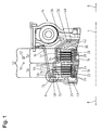
- Fig. 1 shows an embodiment of the multi-plate clutch 2 according to the invention in cross section, with respect to the longitudinal or rotational axis 4, rotate about which the rotatable parts of the multi-plate clutch 2, only a portion of the upper part.
- the two axial directions of the multi-plate clutch 2 are shown with reference to the arrows 6 and 8, while the circumferential directions of the multi-plate clutch 2 are indicated by the arrows 10 and 12.
- the multi-plate clutch 2 is designed as a wet-running multi-plate clutch, which in the present example is a double clutch.
- the multi-plate clutch 2 has a torsional vibration damper 14, which can be rotatably connected on the one hand with a motor-side input shaft, not shown, and on the other hand is in rotary driving connection with a clutch housing 16.
- the coupling housing 16 At its end facing away from the torsional vibration damper 14, the coupling housing 16 is non-rotatably connected to a not shown Sleeve connected, which surrounds the two transmission input shafts, not shown.
- This sleeve is in turn rotatably connected to an inner disk carrier 18.
- the inner disk carrier 18 comprises a first disk support portion 20 located in the axial direction 6 and a second disk support portion 22 located in the axial direction 8.
- the first disk support portion 20 serves to receive inner disks 24 of a first disk pack 26 in a rotationally fixed manner, while the second disk support portion 22 accommodates inner disks 28 a second plate pack 30 is used.
- the first plate set 26 further includes outer plates 32 which are arranged in the axial direction 6 and 8 with the inner plates 24 alternately one behind the other.
- the second disk set 30 comprises outer disks 34, which are arranged alternately one behind the other in the axial direction 6 or 8 with the inner disks 28. While the outer disks 32 of the first disk set 26 are rotationally engaged with a first outer disk carrier 36, the outer disks 34 of the second disk set 30 are rotationally engaged with a second outer disk carrier 38 disposed radially within the first outer disk carrier 36.
- the two outer disk carrier 36, 38 are each a non-illustrated radially inner output hub with one of the transmission input shafts in rotary driving connection.
- Each of the two disk packs 26, 30 is associated with an actuating piston 40, 42, by means of which the associated disk pack 26, 30 can be compressed.
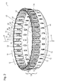
- the outer disk carrier 36 has a substantially plate-shaped, radially outwardly extending support portion 48. At its radially inward-pointing end, the support section 48 is fixed in terms of rotation with an output hub 50 (FIG. Fig. 3 ), via which the outer disk carrier 36 rotatably connected to one of the two transmission input shafts, not shown, is connectable.
- the support portion 48 merges into a tubular portion 52 of the outer disc carrier 36, wherein the tubular portion 52 integrally formed with the support portion 48 extends from the support portion 48 in the axial direction 8.
- the tubular section 52 can be subdivided into a first section 54 which faces or adjoins the support section 48 and a sipe support section 56, the latter being formed in a region of the tubular section 52 facing away from the support section 48.
- a sipe support section 56 forms the Lamellentragabrough 56 on its side facing away from the first portion 54 from the support portion 48 facing away from the edge 58 of the tubular portion 52.
- the sipe supporting portion 56 adjoins the edge 58 of the tubular portion 52.
- the support section 48 and the tubular section 52 in the form of the first section 54 and the slat support section 56 thus form a pot-shaped outer slat carrier 36, whose opening 60 pointing in the axial direction 8 is surrounded by the edge 58.
- the slat support section 56 serves for the non-rotatable mounting of the already with reference to Fig. 1 described outer plate 32 of the first plate pack 26 and has a toothed profile 62 for this purpose.
- the plate support portion 56 in the circumferential direction 10 and 12 distributed, alternately arranged, radially outwardly projecting axial webs 64 and radially inwardly projecting Axialstege 66 to form the Veryakungsprofils 62, wherein between the radially outwardly projecting Axialstegen 64 outer Axialnuten 68 are formed, while between the inwardly projecting Axialstegen 66 inner Axialnuten 70 are formed.
- recesses 72 are formed for centrifugal oil, wherein the recesses 72 are formed in the slat support portion 56 in the radially outwardly projecting axial webs 64.
- the support ring 46 is formed closed, d. H. the support ring 46 has in contrast to the usually used for the axial fixation of fins o. ⁇ . Circlip no interruption, but rather in the circumferential direction 10 and 12 formed continuously.
- the support ring 46 is fixed to the outer slat support 36 so as to surround the slat support portion 56. In this way, the sipe supporting portion 56 of the tubular portion 52 is radially supported outwardly on the inner side of the support ring 46, so that expansion of the tubular portion 52 and the sipe supporting portion 56 in the radial direction is surely prevented.
- the support ring 46 which is separate from the outer disk carrier 36 and thus not integrally formed therewith, is made in the present embodiment of a material whose strength is higher than the strength of the material for the tubular portion 52 of the outer disk carrier 36. Because the danger a widening of the tubular portion 52 in the region of the edge 58 surrounding the opening 60 is greatest, the support ring 46 is arranged with respect to the axial directions 6 and 8 in the region of the support portion 48 facing away from the edge 58 of the tubular portion 52. It is therefore advantageous to arrange the support ring 46 as close as possible to the edge 58, so that the support ring 46 can prevent a widening of the tubular portion 52 in the radial direction in a particularly effective manner.
- the support ring 46 can abut against the tubular section 52 or the slat support section 56, both with play and clamping.
- the support ring 46 is fixed in the axial direction 6 and 8 on the outer disk carrier 36 so that the support ring 46 can not solve in the axial direction 6 or 8 of the outer disk carrier 36 during operation.
- the support ring 46 may optionally be set with play in the axial direction 6 or 8 fixed to the outer disk carrier 36.
- radially outwardly projecting stops 74 and 76 are provided on the tubular portion 52.
- stops 74 serve to support the support ring 46 in the axial direction 8
- the stops 76 are arranged such that they support the support ring 46 in the axial direction 6.
- recesses 78 recessed inward may also be provided on the tubular portion 52 as will be described later with reference to FIG Fig. 7 is explained.
- the stops 74, 76 or recesses 78 are integrally formed with the tubular portion 52 and preferably formed by stamping or punching.
- the stoppers 74, 76 of the present embodiment can be elastically deformed inward in the radial direction, so that a simpler mounting of the support ring 46 on the tubular portion 52 of the outer disk carrier 36 is possible, as will be explained later in more detail.
- the support ring 46 can be positively and / or non-positively attached to the outer disk carrier 36.
- the mounting of the support ring 46 on the tubular portion 52 is facilitated.
- the stops 74, 76 or the depression 78 are provided on the radially outwardly projecting axial webs 64, whereby the manufacturing cost is reduced.
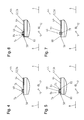
- FIGS Fig. 4 to 7 each of the section A of Fig. 1 represent enlarged, different embodiments of the plate carrier assembly 44 from the Fig. 1 to 3 described.
- Fig. 4 a first embodiment of the plate carrier assembly 44, which is particularly easy to manufacture.
- the two stops 74, 76 are made by embossing the inside of the outwardly projecting Axialsteges 64.
- the stops 74, 76 produced by an embossing process, the material cohesion between the stops 74, 76 on the one hand and the material of the tubular section 52 on the other hand is maintained both in the axial directions 6, 8 and in the circumferential directions 10, 12.
- This has the advantage that the strength of the tubular portion 52 is not lowered so much in this area.
- the elastic deformability of the stops 74, 76 in the radial direction is not as pronounced inwardly, as is the case in the embodiment described below.
- Fig. 5 shows a second embodiment of the plate carrier assembly 44, in which the stops 74 and 76 are each formed as a support tongue 80, 82.
- the support tongues 80, 82 were hereby produced by a stamping process, so that the substance cohesion between the support tongues 80, 82 on the one hand and the remaining material of the tubular portion 52 in at least one of the axial directions 6, 8 is interrupted.
- the substance cohesion between the support tongues 80, 82 on the one hand and the surrounding material of the tubular portion 52 on the other hand is at least partially interrupted in both circumferential directions 10, 12. This can be effected for example by punching a substantially U-shaped recess in the outwardly projecting axial web 64.
- the support tongue 80 has a free end 84 which points in the axial direction 6 and on which the support ring 46 can be supported or supported in the axial direction 8.
- the support tongue 82 has a pointing in the axial direction 8 free end 86 which faces the support ring 46 and on which the support ring 46 is supported or supported in the axial direction 6. Thanks to the better elastic deformability of the support tongues 80, 82 in the radially inward direction, the support ring 46 can be attached to the tubular section 52 in a particularly simple manner by simply slipping it onto the tubular section 52 in one of the axial directions 6, 8. In the second embodiment, the sliding of the support ring 46 on the tubular portion 52 accordingly equally easy in both axial directions 6 and 8 possible. However, should a fixed push-on direction exist, the embodiment described below is preferred.
- Fig. 6 a third embodiment of the disc carrier assembly 44, which is a combination of the first and second embodiments according to the 4 and 5 is.
- the foregoing description of the first and second embodiments applies mutatis mutandis, as far as the same reference numerals are used.
- the support ring 46 in the axial direction 6 must be pushed over the edge 58 on the tubular portion 52 or should, in order to effect a fastening thereof to the outer disk carrier 36.
- the stop 74 which is located closer to the edge 58 than the stop 76, as a punched stop 74 in the form of the support tongue 80 trained.
- the stop 76 which is farther away from the edge 58 than the stop 74 in the form of the support tongue 80, as an embossed stop 76 in the sense of the description Fig. 4 educated.
- the support tongue 80 allows a simple sliding of the support ring 46 on the tubular portion 52, while the embossed stopper 76 allows secure support of the support ring 46 in the axial direction 6, without weakening the tubular portion 52 in the region of the stopper 76 too strong. If the predetermined Aufschiebeoplasty for the support ring 46 correspond to the axial direction 8, a correspondingly reverse design of the stops 74, 76 is advantageous.
- Fig. 7 shows a fourth embodiment of the plate carrier assembly 44, to which already with reference to the Fig. 1 to 3 was received.
- the axial fixation or fixing of the support ring 46 is effected on the tubular portion 52 in this embodiment by recesses 78 in the outwardly projecting Axialstegen 64 by the support ring 46 rests in the recesses 78 and in the axial direction 8 at a first edge 88th the recess 78 and in the axial direction 6 at a second edge 90 of the recess 78 is supported or supported.
- the possibilities of attaching the support ring 46 to the tubular portion 52 in this embodiment will be described in more detail later with reference to FIGS Fig. 9 to 11 received.
- a rigid support ring 46 may be used whose inner diameter is substantially invariable. To secure the support ring 46 to the tubular portion 52, this is pushed in the axial direction 6 over the edge 58 of the tubular portion 52, so that the stop 74 is depressed in the form of the support tongue 80 by the support ring 46 and elastically deformed in the radial direction inwardly.
- the stop 74 Due to the elasticity of the stop 74 in the radial direction, the stop 74 returns in the form of the support tongue 80 after reaching the mounting position of the support ring 46 back into its in Fig. 6 shown initial position, so that the support ring 46 is supported or supportable in the axial direction 8 at the free end 84 of the stop 74 and in the axial direction 6 on the stop 76.
- Fig. 9 shows a second embodiment of the method according to the invention, in particular in the manufacture of the plate carrier assembly 44 according to the fourth embodiment according to Fig. 7 can be used, however, this second embodiment of the method for the manufacture of the plate carrier assemblies 44 from the 4 to 6 be used.
- the second embodiment according to Fig. 9 is in turn designed in particular for a support ring 46 which is rigid and has a substantially unchangeable inner diameter. To secure the support ring 46 to the tubular portion 52, first the tubular portion 52 is elastically compressed inwardly in the radial direction, as indicated by the arrow 92 in FIG Fig. 9 is indicated.
- the 10 and 11 show a fifth embodiment of the disk carrier assembly 44 and its manufacturing method, wherein the outer disk carrier 36 and the support ring 46 are indicated only schematically.
- a support ring 46 is used whose inner diameter can be changed.
- the support ring 46 is formed by a band or rope 94 and arranged on the belt 94 clamping mechanism 96.
- the band 94 which may be formed, for example, as a band-shaped plate is so connected to the clamping mechanism 96 that the band 94 forms an eyelet, the diameter of which can be increased and reduced by means of the clamping mechanism 96.
- the support ring 46 may be formed, for example, in the manner of a clamp.
- one or more recesses 78 for receiving the support ring 46 may be provided on the tubular portion 52 of the outer disk carrier 36.
- the inner diameter thereof may first be increased by means of the tensioning mechanism 96. Subsequently, the thus expanded support ring 46 can be pushed over the edge 58 in the axial direction 6 on the tubular portion 52, which is particularly simple due to the large inner diameter of the support ring 46.
- the inside diameter of the support ring 46 is determined by means of the tensioning mechanism 96 is again reduced, ie the support ring 46 is contracted until the support ring 46 or the band 94 rests in the recess or recesses 78 and is thus fixed in the axial directions 6 and 8 on the tubular portion 52.
- the clamping mechanism 96 is designed such that the inner diameter of the support ring 46 after reaching the mounting position, the in Fig. 11 is shown can be set so that the loop 94 enclosed by the loop during operation of the multi-plate clutch 2 can not expand.
- the disk carrier assembly 44 thus a particularly simple mounting of the support ring 46 on the tubular portion 52 of the outer disk carrier 36 is possible.
- the outer disk carrier 36 in this embodiment is particularly strong to expand in the radial direction under centrifugal force in the region of the tubular portion 52, especially since no drive plate is provided, which could at least partially counteract this expansion.
- the use of the disk carrier assembly 44 in a multi-plate clutch 2 without drive plate for the outer disk carrier 36 is particularly advantageous.
- the present invention also extends to a multi-plate clutch 2 with a drive plate, which is in rotary driving connection with the outer disk carrier 36 and is optionally arranged in front of the opening 60 in the region of the edge 58 of the outer disk carrier 36.
- the support ring 46 is formed separately from the drive plate and not integral therewith.
- the individual components in the form of the outer disk carrier 36, the support ring 46 and the drive plate can be better matched to their intended function.
- the production of the drive plate and its mounting on the outer plate carrier 36 is simplified.
Landscapes
- Engineering & Computer Science (AREA)
- General Engineering & Computer Science (AREA)
- Mechanical Engineering (AREA)
- Mechanical Operated Clutches (AREA)
Applications Claiming Priority (1)
| Application Number | Priority Date | Filing Date | Title |
|---|---|---|---|
| DE102008019164A DE102008019164A1 (de) | 2008-04-17 | 2008-04-17 | Lamellenträgeranordnung mit einem Lamellenträger, Lamellenkupplung mit der Lamellenträgeranordnung und Verfahren zur Herstellung der Lamellenträgeranordnung |
Publications (2)
| Publication Number | Publication Date |
|---|---|
| EP2110574A1 true EP2110574A1 (fr) | 2009-10-21 |
| EP2110574B1 EP2110574B1 (fr) | 2011-10-19 |
Family
ID=40874657
Family Applications (1)
| Application Number | Title | Priority Date | Filing Date |
|---|---|---|---|
| EP09002898A Active EP2110574B1 (fr) | 2008-04-17 | 2009-02-28 | Agencement de support de disques doté d'un support de disques, embrayage à disques doté de l'agencement de support de disques et procédé de fabrication de l'agencement de support de disques |
Country Status (3)
| Country | Link |
|---|---|
| EP (1) | EP2110574B1 (fr) |
| DE (1) | DE102008019164A1 (fr) |
| ES (1) | ES2373013T3 (fr) |
Cited By (1)
| Publication number | Priority date | Publication date | Assignee | Title |
|---|---|---|---|---|
| CN104179820A (zh) * | 2013-05-27 | 2014-12-03 | 大众汽车有限公司 | 用于多片式离合器的摩擦片支架装置 |
Families Citing this family (7)
| Publication number | Priority date | Publication date | Assignee | Title |
|---|---|---|---|---|
| DE102010008735A1 (de) * | 2010-02-20 | 2011-10-06 | Volkswagen Ag | Lamellenträger für eine Lamellenkupplung und Verfahren zur Herstellung eines Lamellenträgers |
| DE102013021659A1 (de) | 2013-12-19 | 2015-06-25 | Borgwarner Inc. | Lamellentrageinrichtung und Verfahren zur Herstellung einer Lamellentrageinrichtung |
| DE102014014235A1 (de) | 2014-09-25 | 2016-03-31 | Borgwarner Inc. | Lamellentrageinrichtung, Lamellenkupplung oder -bremse und Verfahren zur Herstellung einer Lamellentrageinrichtung |
| DE102014118132B3 (de) * | 2014-12-08 | 2016-03-03 | Winkelmann MSR Technology GmbH & Co. KG | Innenlamellenträger für ein Lamellenschaltelement einer Kupplung |
| DE102016010994A1 (de) | 2015-11-06 | 2017-05-11 | Borgwarner Inc. | Verfahren zur Herstellung einer Lamellentrageinrichtung und Lamellentrageinrichtung |
| DE202016106877U1 (de) * | 2016-12-09 | 2017-01-10 | Fischer & Kaufmann Gmbh & Co. Kg | Lamellenträger |
| JP7116791B2 (ja) * | 2017-11-27 | 2022-08-10 | エンデュランス アドラー ソシエタ ペル アチオニ | 特に自動二輪車のための、プレッシャープレートおよび遠心アセンブリを備えるクラッチ |
Citations (7)
| Publication number | Priority date | Publication date | Assignee | Title |
|---|---|---|---|---|
| US4813522A (en) * | 1982-06-21 | 1989-03-21 | Nissan Motor Company, Limited | Clutch drum |
| US5180043A (en) * | 1992-02-20 | 1993-01-19 | Koppy Corporation | Splined assembly |
| US6158265A (en) * | 1997-03-20 | 2000-12-12 | Koppy Corporation | Method of forming retaining members on a housing |
| US20040035667A1 (en) * | 2002-08-23 | 2004-02-26 | Prater Ronald E. | Clutch assembly including strengthening members |
| US6929107B2 (en) | 2000-10-05 | 2005-08-16 | Ford Global Technologies, Llc | Dual clutch for a transmission with two input shafts |
| WO2006093396A1 (fr) | 2005-03-04 | 2006-09-08 | Jinmyung Frictech Co., Ltd | Embrayage a friction presentant des lamelles multiples de friction, carter d’embrayage, procede de fabrication du carter d’embrayage et systeme pour l’embrayage a friction presentant des lamelles multiples de friction |
| WO2007095884A1 (fr) * | 2006-02-22 | 2007-08-30 | Luk Lamellen Und Kupplungsbau Beteiligungs Kg | Carter d'embrayage comportant des fentes d'arrêt pour des ressorts de levier, et procédé d'intégration d'un ressort de levier |
Family Cites Families (3)
| Publication number | Priority date | Publication date | Assignee | Title |
|---|---|---|---|---|
| US4014619A (en) * | 1975-09-29 | 1977-03-29 | Koppy Corporation | Retainer ring and splined member assembly |
| DE3936871C2 (de) * | 1988-11-17 | 1998-09-10 | Volkswagen Ag | Hohlzylindrisches Gehäuseteil |
| US4945782A (en) * | 1989-04-28 | 1990-08-07 | General Motors Corporation | Mounting device for securing a ring gear to a drive drum |
-
2008
- 2008-04-17 DE DE102008019164A patent/DE102008019164A1/de not_active Withdrawn
-
2009
- 2009-02-28 ES ES09002898T patent/ES2373013T3/es active Active
- 2009-02-28 EP EP09002898A patent/EP2110574B1/fr active Active
Patent Citations (7)
| Publication number | Priority date | Publication date | Assignee | Title |
|---|---|---|---|---|
| US4813522A (en) * | 1982-06-21 | 1989-03-21 | Nissan Motor Company, Limited | Clutch drum |
| US5180043A (en) * | 1992-02-20 | 1993-01-19 | Koppy Corporation | Splined assembly |
| US6158265A (en) * | 1997-03-20 | 2000-12-12 | Koppy Corporation | Method of forming retaining members on a housing |
| US6929107B2 (en) | 2000-10-05 | 2005-08-16 | Ford Global Technologies, Llc | Dual clutch for a transmission with two input shafts |
| US20040035667A1 (en) * | 2002-08-23 | 2004-02-26 | Prater Ronald E. | Clutch assembly including strengthening members |
| WO2006093396A1 (fr) | 2005-03-04 | 2006-09-08 | Jinmyung Frictech Co., Ltd | Embrayage a friction presentant des lamelles multiples de friction, carter d’embrayage, procede de fabrication du carter d’embrayage et systeme pour l’embrayage a friction presentant des lamelles multiples de friction |
| WO2007095884A1 (fr) * | 2006-02-22 | 2007-08-30 | Luk Lamellen Und Kupplungsbau Beteiligungs Kg | Carter d'embrayage comportant des fentes d'arrêt pour des ressorts de levier, et procédé d'intégration d'un ressort de levier |
Cited By (2)
| Publication number | Priority date | Publication date | Assignee | Title |
|---|---|---|---|---|
| CN104179820A (zh) * | 2013-05-27 | 2014-12-03 | 大众汽车有限公司 | 用于多片式离合器的摩擦片支架装置 |
| CN104179820B (zh) * | 2013-05-27 | 2017-04-12 | 大众汽车有限公司 | 用于多片式离合器的摩擦片支架装置 |
Also Published As
| Publication number | Publication date |
|---|---|
| EP2110574B1 (fr) | 2011-10-19 |
| ES2373013T3 (es) | 2012-01-30 |
| DE102008019164A1 (de) | 2009-10-22 |
Similar Documents
| Publication | Publication Date | Title |
|---|---|---|
| EP2110574B1 (fr) | Agencement de support de disques doté d'un support de disques, embrayage à disques doté de l'agencement de support de disques et procédé de fabrication de l'agencement de support de disques | |
| EP2469114B1 (fr) | Dispositif de couplage | |
| DE102009057353A1 (de) | Lamellenkupplung mit einer Federeinrichtung | |
| DE102011122741A1 (de) | Kupplungseinrichtung | |
| DE102008063662A1 (de) | Lamelle für eine reibschlüssig arbeitende Einrichtung und reibschlüssig arbeitende Einrichtung mit einer solchen Lamelle | |
| DE102009012283A1 (de) | Mehrfachkupplungseinrichtung mit einem Drehmomentübertragungselement und Getriebe-Kupplungs-Anordnung mit einer solchen Mehrfachkupplungseinrichtung | |
| DE102015213874A1 (de) | Axiale Lamellenkupplung | |
| DE102012017951A1 (de) | Betätigungselement zur Betätigung eines Lamellenpakets und parallele Doppelkupplungseinrichtung mit einem solchen Betätigungselement | |
| DE102013008954A1 (de) | Lamellenträgeranordnung für eine Lamellenkupplung | |
| DE102007031963A1 (de) | Kupplung, vzw. Doppelkupplung für ein Kraftfahrzeug | |
| DE112010002439T5 (de) | Drehmomentbegrenzer | |
| DE102010044379A1 (de) | Kupplung | |
| EP3105464A1 (fr) | Dispositif d'embrayage normalement embrayé | |
| DE102012218829A1 (de) | Doppelkupplung und Verfahren zu deren Montage | |
| EP3164615A1 (fr) | Disque d'embrayage | |
| WO2018202236A1 (fr) | Dispositif d'embrayage | |
| DE102007027117A1 (de) | Kupplung | |
| EP3325836B1 (fr) | Ensemble de disques pour embrayage à disques multiples | |
| DE102017126999A1 (de) | Lageranordnung | |
| DE102015212662A1 (de) | Reibschaltelement für ein Getriebe eines Fahrzeuges | |
| DE102009058129A1 (de) | Endlamelle für ein Lamellenpaket, reibschlüssig arbeitende Einrichtung mit einer solchen Endlamelle und Verfahren zur Herstellung einer solchen Endlamelle | |
| DE102008038101B4 (de) | Kupplungs-Dämpfer-Einheit | |
| DE112014002407B4 (de) | Kupplungsvorrichtung mit Verschleißnachstelleinrichtung | |
| DE102016011904A1 (de) | Doppelkupplungseinrichtung | |
| DE102010036280B4 (de) | Transmitter für eine Synchronisierungsbaugruppe eines Schaltgetriebes |
Legal Events
| Date | Code | Title | Description |
|---|---|---|---|
| PUAI | Public reference made under article 153(3) epc to a published international application that has entered the european phase |
Free format text: ORIGINAL CODE: 0009012 |
|
| AK | Designated contracting states |
Kind code of ref document: A1 Designated state(s): AT BE BG CH CY CZ DE DK EE ES FI FR GB GR HR HU IE IS IT LI LT LU LV MC MK MT NL NO PL PT RO SE SI SK TR |
|
| AX | Request for extension of the european patent |
Extension state: AL BA RS |
|
| 17P | Request for examination filed |
Effective date: 20100226 |
|
| 17Q | First examination report despatched |
Effective date: 20100326 |
|
| AKX | Designation fees paid |
Designated state(s): AT BE BG CH CY CZ DE DK EE ES FI FR GB GR HR HU IE IS IT LI LT LU LV MC MK MT NL NO PL PT RO SE SI SK TR |
|
| GRAP | Despatch of communication of intention to grant a patent |
Free format text: ORIGINAL CODE: EPIDOSNIGR1 |
|
| GRAS | Grant fee paid |
Free format text: ORIGINAL CODE: EPIDOSNIGR3 |
|
| GRAA | (expected) grant |
Free format text: ORIGINAL CODE: 0009210 |
|
| RBV | Designated contracting states (corrected) |
Designated state(s): DE ES FR GB IT |
|
| AK | Designated contracting states |
Kind code of ref document: B1 Designated state(s): DE ES FR GB IT |
|
| REG | Reference to a national code |
Ref country code: GB Ref legal event code: FG4D Free format text: NOT ENGLISH |
|
| REG | Reference to a national code |
Ref country code: DE Ref legal event code: R096 Ref document number: 502009001608 Country of ref document: DE Effective date: 20111215 |
|
| REG | Reference to a national code |
Ref country code: ES Ref legal event code: FG2A Ref document number: 2373013 Country of ref document: ES Kind code of ref document: T3 Effective date: 20120130 |
|
| PLBE | No opposition filed within time limit |
Free format text: ORIGINAL CODE: 0009261 |
|
| STAA | Information on the status of an ep patent application or granted ep patent |
Free format text: STATUS: NO OPPOSITION FILED WITHIN TIME LIMIT |
|
| 26N | No opposition filed |
Effective date: 20120720 |
|
| REG | Reference to a national code |
Ref country code: DE Ref legal event code: R097 Ref document number: 502009001608 Country of ref document: DE Effective date: 20120720 |
|
| REG | Reference to a national code |
Ref country code: FR Ref legal event code: PLFP Year of fee payment: 8 |
|
| REG | Reference to a national code |
Ref country code: FR Ref legal event code: PLFP Year of fee payment: 9 |
|
| REG | Reference to a national code |
Ref country code: FR Ref legal event code: PLFP Year of fee payment: 10 |
|
| P01 | Opt-out of the competence of the unified patent court (upc) registered |
Effective date: 20230327 |
|
| PGFP | Annual fee paid to national office [announced via postgrant information from national office to epo] |
Ref country code: GB Payment date: 20260113 Year of fee payment: 18 |
|
| PGFP | Annual fee paid to national office [announced via postgrant information from national office to epo] |
Ref country code: ES Payment date: 20260304 Year of fee payment: 18 |
|
| PGFP | Annual fee paid to national office [announced via postgrant information from national office to epo] |
Ref country code: DE Payment date: 20260115 Year of fee payment: 18 |
|
| PGFP | Annual fee paid to national office [announced via postgrant information from national office to epo] |
Ref country code: IT Payment date: 20260212 Year of fee payment: 18 |
|
| PGFP | Annual fee paid to national office [announced via postgrant information from national office to epo] |
Ref country code: FR Payment date: 20260109 Year of fee payment: 18 |