EP2110601A1 - Brûleur - Google Patents
Brûleur Download PDFInfo
- Publication number
- EP2110601A1 EP2110601A1 EP08007392A EP08007392A EP2110601A1 EP 2110601 A1 EP2110601 A1 EP 2110601A1 EP 08007392 A EP08007392 A EP 08007392A EP 08007392 A EP08007392 A EP 08007392A EP 2110601 A1 EP2110601 A1 EP 2110601A1
- Authority
- EP
- European Patent Office
- Prior art keywords
- burner
- burner according
- swirler
- mixing cavity
- wings
- Prior art date
- Legal status (The legal status is an assumption and is not a legal conclusion. Google has not performed a legal analysis and makes no representation as to the accuracy of the status listed.)
- Withdrawn
Links
Images


Classifications
-
- F—MECHANICAL ENGINEERING; LIGHTING; HEATING; WEAPONS; BLASTING
- F23—COMBUSTION APPARATUS; COMBUSTION PROCESSES
- F23D—BURNERS
- F23D14/00—Burners for combustion of a gas, e.g. of a gas stored under pressure as a liquid
- F23D14/02—Premix gas burners, i.e. in which gaseous fuel is mixed with combustion air upstream of the combustion zone
-
- F—MECHANICAL ENGINEERING; LIGHTING; HEATING; WEAPONS; BLASTING
- F23—COMBUSTION APPARATUS; COMBUSTION PROCESSES
- F23D—BURNERS
- F23D11/00—Burners using a direct spraying action of liquid droplets or vaporised liquid into the combustion space
- F23D11/10—Burners using a direct spraying action of liquid droplets or vaporised liquid into the combustion space the spraying being induced by a gaseous medium, e.g. water vapour
- F23D11/101—Burners using a direct spraying action of liquid droplets or vaporised liquid into the combustion space the spraying being induced by a gaseous medium, e.g. water vapour medium and fuel meeting before the burner outlet
- F23D11/102—Burners using a direct spraying action of liquid droplets or vaporised liquid into the combustion space the spraying being induced by a gaseous medium, e.g. water vapour medium and fuel meeting before the burner outlet in an internal mixing chamber
- F23D11/103—Burners using a direct spraying action of liquid droplets or vaporised liquid into the combustion space the spraying being induced by a gaseous medium, e.g. water vapour medium and fuel meeting before the burner outlet in an internal mixing chamber with means creating a swirl inside the mixing chamber
-
- F—MECHANICAL ENGINEERING; LIGHTING; HEATING; WEAPONS; BLASTING
- F23—COMBUSTION APPARATUS; COMBUSTION PROCESSES
- F23D—BURNERS
- F23D14/00—Burners for combustion of a gas, e.g. of a gas stored under pressure as a liquid
- F23D14/46—Details
- F23D14/72—Safety devices, e.g. operative in case of failure of gas supply
- F23D14/82—Preventing flashback or blowback
-
- F—MECHANICAL ENGINEERING; LIGHTING; HEATING; WEAPONS; BLASTING
- F23—COMBUSTION APPARATUS; COMBUSTION PROCESSES
- F23R—GENERATING COMBUSTION PRODUCTS OF HIGH PRESSURE OR HIGH VELOCITY, e.g. GAS-TURBINE COMBUSTION CHAMBERS
- F23R3/00—Continuous combustion chambers using liquid or gaseous fuel
- F23R3/28—Continuous combustion chambers using liquid or gaseous fuel characterised by the fuel supply
- F23R3/286—Continuous combustion chambers using liquid or gaseous fuel characterised by the fuel supply having fuel-air premixing devices
-
- F—MECHANICAL ENGINEERING; LIGHTING; HEATING; WEAPONS; BLASTING
- F23—COMBUSTION APPARATUS; COMBUSTION PROCESSES
- F23R—GENERATING COMBUSTION PRODUCTS OF HIGH PRESSURE OR HIGH VELOCITY, e.g. GAS-TURBINE COMBUSTION CHAMBERS
- F23R3/00—Continuous combustion chambers using liquid or gaseous fuel
- F23R3/28—Continuous combustion chambers using liquid or gaseous fuel characterised by the fuel supply
- F23R3/34—Feeding into different combustion zones
- F23R3/343—Pilot flames, i.e. fuel nozzles or injectors using only a very small proportion of the total fuel to insure continuous combustion
-
- F—MECHANICAL ENGINEERING; LIGHTING; HEATING; WEAPONS; BLASTING
- F23—COMBUSTION APPARATUS; COMBUSTION PROCESSES
- F23D—BURNERS
- F23D2209/00—Safety arrangements
- F23D2209/10—Flame flashback
-
- F—MECHANICAL ENGINEERING; LIGHTING; HEATING; WEAPONS; BLASTING
- F23—COMBUSTION APPARATUS; COMBUSTION PROCESSES
- F23D—BURNERS
- F23D2900/00—Special features of, or arrangements for burners using fluid fuels or solid fuels suspended in a carrier gas
- F23D2900/14—Special features of gas burners
- F23D2900/14003—Special features of gas burners with more than one nozzle
-
- F—MECHANICAL ENGINEERING; LIGHTING; HEATING; WEAPONS; BLASTING
- F23—COMBUSTION APPARATUS; COMBUSTION PROCESSES
- F23D—BURNERS
- F23D2900/00—Special features of, or arrangements for burners using fluid fuels or solid fuels suspended in a carrier gas
- F23D2900/14—Special features of gas burners
- F23D2900/14021—Premixing burners with swirling or vortices creating means for fuel or air
-
- F—MECHANICAL ENGINEERING; LIGHTING; HEATING; WEAPONS; BLASTING
- F23—COMBUSTION APPARATUS; COMBUSTION PROCESSES
- F23D—BURNERS
- F23D2900/00—Special features of, or arrangements for burners using fluid fuels or solid fuels suspended in a carrier gas
- F23D2900/14—Special features of gas burners
- F23D2900/14701—Swirling means inside the mixing tube or chamber to improve premixing
Definitions
- the present invention relates to a burner with a burner head according to the features of the preamble of claim 1.
- Such burners are preferably adapted for firing the combustion chamber of a gas turbine.
- a burner known from EP 1 389 714 A1 comprises a swirl generator and a downstream mixing tube.
- the burner head is provided with a pilot burner system to support the main flame.
- the pilot burner system comprises a mixing cavity for mixing pilot fuel and assist air.
- the mixing cavity of the known burner is of a pure circumferential shape. Within such a designed mixing cavity there is a risk for the pilot flame to burn inside.
- the object of the present invention is to improve a burner head of the above type in such away that a risk of a flash back, i. e. upstream propagation of the flame, is minimized.
- the swirl wings inside the mixing cavity of the inventive burner head induce a swirl to the incoming assist air flow.
- the air flow afflicted with the swirl forces the fuel to stay inside the outlet nozzles and not to "leak out” into the mixing cavity.
- the present burner comprises a cylindrical burner head and an upstream swirl generator.
- a number of such burners are used for burning a fuel/air mixture in a combustion chamber of a gas turbine.
- the burner head is shown only, because the invention relates to an improvement of the burner head, and the swirl generator is well known in the prior art, e. g. from EP 1 389 714 A1 .
- the not shown swirl generator is swirling an air stream which enters the swirl generator via slots.
- a fuel is introduced into the air stream.
- the premixed swirling mixture of air and fuel enters the mixing tube for further mixing before leaving the discharge end of the burner head.
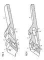
- the burner head according to the invention comprises three parts, namely a burner tip 1, a spacer ring 2, and a mixing tube 3. These three parts are joined across the lines A and B ( Fig. 3, 4) . Along these lines A and B the parts can be partly welded or brazed together. One of the weldings is shown as a welding seam 4 in Fig. 2 . When assembled the back face of the burner tip 1 abuts the front face of the spacer ring 2, and the back face of the spacer ring 2 abuts the front face of the mixing tube 3.
- the burner tip 1 has a rounded inner surface 5 and a conical front surface 6.
- the burner is operated under lean conditions. If the load is reduced, the burner has a tendency to become unstable when the supply with fuel is reduced. To maintain stable conditions even at low load the burner is provided with a pilot burner system which will now be described in detail.
- the pilot burner system comprises a number of outlet nozzles 7 provided on the conical front surface 6 of the burner tip 1.
- the axis of these outlet nozzles 7 is substantially perpendicular to the plane of the conical front surface 6.
- the outlet nozzle 7 has the shape of a cylinder 8 and can preferably be provided with a cone 9 having a chamfered edge at the outlet side.
- the cross section of the outlet nozzle 7 is preferably circular or arbitrary; e. g. conical, elliptical or of any other appropriate shape. Due to the chamfered edge of the cone 9 at the outlet side the outlet nozzle 7 avoids sharp edges which may cause high stress concentration and may crack by time.
- the outlet nozzles 7 communicate with an annular mixing cavity 10 provided inside the burner tip 1.
- Gas channels 11 conducting a gaseous pilot fuel are arranged in longitudinal direction inside the spacer ring 2 of the burner head.
- the gas channels 11 emerge into the mixing cavity 10.
- the gas channels 11 connect the mixing cavity 10 to an annular gas manifold 12 which is arranged inside the burner head at the connection between the spacer ring 2 and mixing tube 3.
- a not shown pipe supplied the pilot gas through an opening 13 arranged in the spacer ring 2 of the burner head into the gas manifold 12.
- Assist air for burning the pilot gas is led in through air channels 14 with air inlets 15 on the circumference of the spacer ring 2 of the burner head.
- the air channels 14 are designed as bores through longitudinal side wall of the spacer ring 2 of the burner head.
- Each air channel 14 ends in several, preferably in two impingement holes 16.
- the impingement holes 16 emerge into the mixing cavity 10 by the side of the entrance of the pilot gas.
- the air coming out from said impingement holes 16 is deflected 90 degrees to the sides along the mixing cavity 10.
- the arrangement of several impingement holes 16 improve cooling of the burner tip 1.
- pilot fuel e. g. oil
- the pilot oil is supplied through an oil pipe 17 which communicates with a separate oil channel inside the burner head. The discharge end of the oil channel emerges into the mixing cavity 10 in alignment with one of the outlet nozzles 7.
- swirler wings 18 are located inside the mixing cavity 10. They are fully or almost fully covering the height of the mixing cavity 10 in the longitudinal direction and are fully integrated with the burner tip 1. Two swirler wings 18 are arranged as a pair respectively. One swirler wing 18 of each pair of swirler wings 18 is located in the outer part and one in the inner part of the mixing cavity 10 in radial direction.
- the swirler wings 18 or each pair of swirler wings 18 are located in the vicinity of one of the outlet nozzles 7. Thereby the assist air following the mixing cavity 10 to the outlet nozzle 7 is forced to swirl around the flow of pilot gas coming from the gas channel 11 and generating a swirl of well defined mixed pilot gas and assist air.
- the swirler wings 18 and the cylinder 8 of the outlet nozzles 7 are designed in such a way as to minimize the risk of flash back, that is the upstream propagation of the flame, by controlling the fuel distribution and the velocity components in axial and tangential direction of the outlet nozzle 7.
- the incoming assist air flow generated by the swirler wings 18 will also force the pilot gas to stay inside the outlet nozzle 7 and not to "leak out" into the mixing cavity 10 between two pairs of swirler wings 18 near the two impingement holes 16.
- the swirler wings 18 are also designed to act as effective cooling fins, due to that they are surrounded with cool air at a high velocity, that substantially improve cooling of the hot burner tip 1.
- a secondary effect of the swirler wings 18 is that they even out the velocity distribution in the mixing cavity 10 resulting in a more uniform cooling of the entire burner tip 1.
- the swirler wings 18 could be manufactured in a cost effective way by using standard milling tools.
Landscapes
- Engineering & Computer Science (AREA)
- Chemical & Material Sciences (AREA)
- Combustion & Propulsion (AREA)
- Mechanical Engineering (AREA)
- General Engineering & Computer Science (AREA)
- Gas Burners (AREA)
Priority Applications (6)
| Application Number | Priority Date | Filing Date | Title |
|---|---|---|---|
| EP08007392A EP2110601A1 (fr) | 2008-04-15 | 2008-04-15 | Brûleur |
| PCT/EP2009/054365 WO2009127606A1 (fr) | 2008-04-15 | 2009-04-14 | Brûleur |
| US12/937,770 US9074764B2 (en) | 2008-04-15 | 2009-04-14 | Burner having a pilot burner system with swirler wings and a plurality of outlet nozzles |
| CN2009801135022A CN102007341A (zh) | 2008-04-15 | 2009-04-14 | 燃烧器 |
| RU2010146228/06A RU2459146C2 (ru) | 2008-04-15 | 2009-04-14 | Горелка |
| EP09733156.5A EP2268975B1 (fr) | 2008-04-15 | 2009-04-14 | Brûleur |
Applications Claiming Priority (1)
| Application Number | Priority Date | Filing Date | Title |
|---|---|---|---|
| EP08007392A EP2110601A1 (fr) | 2008-04-15 | 2008-04-15 | Brûleur |
Publications (1)
| Publication Number | Publication Date |
|---|---|
| EP2110601A1 true EP2110601A1 (fr) | 2009-10-21 |
Family
ID=40122370
Family Applications (2)
| Application Number | Title | Priority Date | Filing Date |
|---|---|---|---|
| EP08007392A Withdrawn EP2110601A1 (fr) | 2008-04-15 | 2008-04-15 | Brûleur |
| EP09733156.5A Active EP2268975B1 (fr) | 2008-04-15 | 2009-04-14 | Brûleur |
Family Applications After (1)
| Application Number | Title | Priority Date | Filing Date |
|---|---|---|---|
| EP09733156.5A Active EP2268975B1 (fr) | 2008-04-15 | 2009-04-14 | Brûleur |
Country Status (5)
| Country | Link |
|---|---|
| US (1) | US9074764B2 (fr) |
| EP (2) | EP2110601A1 (fr) |
| CN (1) | CN102007341A (fr) |
| RU (1) | RU2459146C2 (fr) |
| WO (1) | WO2009127606A1 (fr) |
Cited By (4)
| Publication number | Priority date | Publication date | Assignee | Title |
|---|---|---|---|---|
| EP2848867A1 (fr) | 2013-09-11 | 2015-03-18 | Electrolux Appliances Aktiebolag | Appareil domestique et procédé d'assemblage de l'appareil domestique |
| EP2905539A1 (fr) * | 2014-02-07 | 2015-08-12 | Siemens Aktiengesellschaft | Veilleuse avec aubes axiales pour turbine à gaz |
| CZ309146B6 (cs) * | 2021-01-27 | 2022-03-09 | Lersen CZ s.r.o. | Kanálková soustava pro vedení předmísené směsi plynného paliva se vzduchem v hlavici premixového hořáku pro spalování předmísené směsi plynného paliva se vzduchem, kanálková vložka pro tuto hlavici a premixový hořák |
| CN114935145A (zh) * | 2022-05-30 | 2022-08-23 | 杭州老板电器股份有限公司 | 带有引射混合系统的燃烧器及燃气灶 |
Families Citing this family (25)
| Publication number | Priority date | Publication date | Assignee | Title |
|---|---|---|---|---|
| EP2650612A1 (fr) | 2012-04-10 | 2013-10-16 | Siemens Aktiengesellschaft | Brûleur |
| US11015809B2 (en) | 2014-12-30 | 2021-05-25 | General Electric Company | Pilot nozzle in gas turbine combustor |
| USD787041S1 (en) | 2015-09-17 | 2017-05-16 | Whirlpool Corporation | Gas burner |
| US10837651B2 (en) | 2015-09-24 | 2020-11-17 | Whirlpool Corporation | Oven cavity connector for operating power accessory trays for cooking appliance |
| US11777190B2 (en) | 2015-12-29 | 2023-10-03 | Whirlpool Corporation | Appliance including an antenna using a portion of appliance as a ground plane |
| US10197279B2 (en) | 2016-06-22 | 2019-02-05 | General Electric Company | Combustor assembly for a turbine engine |
| US10337738B2 (en) | 2016-06-22 | 2019-07-02 | General Electric Company | Combustor assembly for a turbine engine |
| US11022313B2 (en) | 2016-06-22 | 2021-06-01 | General Electric Company | Combustor assembly for a turbine engine |
| US10145568B2 (en) | 2016-06-27 | 2018-12-04 | Whirlpool Corporation | High efficiency high power inner flame burner |
| EP3290804A1 (fr) * | 2016-08-31 | 2018-03-07 | Siemens Aktiengesellschaft | Brûleur avec alimentation d'air et de carburant incorporée dans une paroi du brûleur |
| CN106762225B (zh) * | 2016-11-22 | 2018-08-03 | 上海空间推进研究所 | 一种火箭发动机用防回火喷嘴 |
| DE102017200106A1 (de) * | 2017-01-05 | 2018-07-05 | Siemens Aktiengesellschaft | Brennerspitze mit einem Luftkanalsystem und einem Brennstoffkanalsystem für einen Brenner und Verfahren zu deren Herstellung |
| US10551056B2 (en) | 2017-02-23 | 2020-02-04 | Whirlpool Corporation | Burner base |
| US10451290B2 (en) | 2017-03-07 | 2019-10-22 | Whirlpool Corporation | Forced convection steam assembly |
| US10660162B2 (en) | 2017-03-16 | 2020-05-19 | Whirlpool Corporation | Power delivery system for an induction cooktop with multi-output inverters |
| US10627116B2 (en) | 2018-06-26 | 2020-04-21 | Whirlpool Corporation | Ventilation system for cooking appliance |
| US10619862B2 (en) | 2018-06-28 | 2020-04-14 | Whirlpool Corporation | Frontal cooling towers for a ventilation system of a cooking appliance |
| US10837652B2 (en) | 2018-07-18 | 2020-11-17 | Whirlpool Corporation | Appliance secondary door |
| CN109028059B (zh) * | 2018-09-03 | 2024-02-02 | 哈尔滨电气股份有限公司 | 具有高效燃气空气掺混结构的全预混表面式燃烧器 |
| EP3620718A1 (fr) | 2018-09-07 | 2020-03-11 | Siemens Aktiengesellschaft | Brûleur de turbine à gaz à mélange d'air et de carburant pilote |
| US11181269B2 (en) | 2018-11-15 | 2021-11-23 | General Electric Company | Involute trapped vortex combustor assembly |
| KR102764374B1 (ko) * | 2020-12-18 | 2025-02-07 | 한화에어로스페이스 주식회사 | 연료 공급 장치 |
| US12158268B2 (en) | 2021-06-08 | 2024-12-03 | Forney Corporation | High-capacity igniter |
| US11692711B2 (en) | 2021-08-13 | 2023-07-04 | General Electric Company | Pilot burner for combustor |
| KR102607178B1 (ko) | 2022-01-18 | 2023-11-29 | 두산에너빌리티 주식회사 | 연소기용 노즐, 연소기 및 이를 포함하는 가스 터빈 |
Citations (5)
| Publication number | Priority date | Publication date | Assignee | Title |
|---|---|---|---|---|
| EP0101109A2 (fr) * | 1982-08-09 | 1984-02-22 | Shell Internationale Researchmaatschappij B.V. | Atomiseur-mélangeur |
| US6036475A (en) * | 1997-09-03 | 2000-03-14 | Takuma Co. Ld. | Cyclonic type combustion apparatus |
| WO2000025065A1 (fr) * | 1998-10-23 | 2000-05-04 | Leiv Eiriksson Nyfotek As | Bruleur a gaz |
| US6179608B1 (en) * | 1999-05-28 | 2001-01-30 | Precision Combustion, Inc. | Swirling flashback arrestor |
| EP1389713A1 (fr) * | 2002-08-12 | 2004-02-18 | ALSTOM (Switzerland) Ltd | Brûleur pilote annulaire pour sortie de brûleur à prémélange |
Family Cites Families (13)
| Publication number | Priority date | Publication date | Assignee | Title |
|---|---|---|---|---|
| SU1090969A1 (ru) * | 1983-01-11 | 1984-05-07 | Среднеазиатский Филиал Всесоюзного Научно-Исследовательского Института Использования Газа В Народном Хозяйстве И Подземного Хранения Нефти,Нефтепродуктов И Сжиженных Газов | Турбинна горелка |
| SU1315729A1 (ru) * | 1986-01-23 | 1987-06-07 | Среднеазиатский Филиал Всесоюзного Научно-Исследовательского Института Использования Газа В Народном Хозяйстве И Подземного Хранения Нефти,Нефтепродуктов И Сжиженных Газов | Турбинна горелка |
| SU1476251A2 (ru) | 1987-04-07 | 1989-04-30 | Среднеазиатский Филиал Всесоюзного Научно-Исследовательского Института Использования Газа В Народном Хозяйстве И Подземного Хранения Нефти, Нефтепродуктов И Сжиженных Газов | Горелка |
| RU1789295C (ru) | 1989-06-26 | 1993-01-23 | Проектно-Конструкторский Технологический Институт "Молдсельхозтехпроект" | Горелка дл газопорошковой наплавки |
| SU1763835A1 (ru) * | 1989-12-13 | 1992-09-23 | Среднеазиатский Филиал Всесоюзного Научно-Исследовательского Института Использования Газа В Народном Хозяйстве И Подземного Хранения Нефти, Нефтепродуктов И Сжиженных Газов | Многосопловое горелочное устройство вращающейс печи |
| US5361586A (en) * | 1993-04-15 | 1994-11-08 | Westinghouse Electric Corporation | Gas turbine ultra low NOx combustor |
| US5836164A (en) * | 1995-01-30 | 1998-11-17 | Hitachi, Ltd. | Gas turbine combustor |
| EP0909921B1 (fr) * | 1997-10-14 | 2003-01-02 | Alstom | Brûleur pour la mise en oeuvre d'un générateur de chaleur |
| EP0987493B1 (fr) * | 1998-09-16 | 2003-08-06 | Abb Research Ltd. | Brûleur pour générateur de chaleur |
| US6363724B1 (en) * | 2000-08-31 | 2002-04-02 | General Electric Company | Gas only nozzle fuel tip |
| CN1328497C (zh) * | 2004-04-08 | 2007-07-25 | 中国科学院工程热物理研究所 | 用于柴油机冷启动的辅助预混燃烧装置 |
| EP1999410B1 (fr) * | 2006-03-27 | 2015-12-02 | Alstom Technology Ltd | Bruleur pour le fonctionnement d'un generateur de chaleur |
| US8528334B2 (en) * | 2008-01-16 | 2013-09-10 | Solar Turbines Inc. | Flow conditioner for fuel injector for combustor and method for low-NOx combustor |
-
2008
- 2008-04-15 EP EP08007392A patent/EP2110601A1/fr not_active Withdrawn
-
2009
- 2009-04-14 RU RU2010146228/06A patent/RU2459146C2/ru active
- 2009-04-14 EP EP09733156.5A patent/EP2268975B1/fr active Active
- 2009-04-14 CN CN2009801135022A patent/CN102007341A/zh active Pending
- 2009-04-14 US US12/937,770 patent/US9074764B2/en active Active
- 2009-04-14 WO PCT/EP2009/054365 patent/WO2009127606A1/fr not_active Ceased
Patent Citations (5)
| Publication number | Priority date | Publication date | Assignee | Title |
|---|---|---|---|---|
| EP0101109A2 (fr) * | 1982-08-09 | 1984-02-22 | Shell Internationale Researchmaatschappij B.V. | Atomiseur-mélangeur |
| US6036475A (en) * | 1997-09-03 | 2000-03-14 | Takuma Co. Ld. | Cyclonic type combustion apparatus |
| WO2000025065A1 (fr) * | 1998-10-23 | 2000-05-04 | Leiv Eiriksson Nyfotek As | Bruleur a gaz |
| US6179608B1 (en) * | 1999-05-28 | 2001-01-30 | Precision Combustion, Inc. | Swirling flashback arrestor |
| EP1389713A1 (fr) * | 2002-08-12 | 2004-02-18 | ALSTOM (Switzerland) Ltd | Brûleur pilote annulaire pour sortie de brûleur à prémélange |
Cited By (5)
| Publication number | Priority date | Publication date | Assignee | Title |
|---|---|---|---|---|
| EP2848867A1 (fr) | 2013-09-11 | 2015-03-18 | Electrolux Appliances Aktiebolag | Appareil domestique et procédé d'assemblage de l'appareil domestique |
| EP2905539A1 (fr) * | 2014-02-07 | 2015-08-12 | Siemens Aktiengesellschaft | Veilleuse avec aubes axiales pour turbine à gaz |
| WO2015117794A1 (fr) * | 2014-02-07 | 2015-08-13 | Siemens Aktiengesellschaft | Brûleur à flamme pilote à coupelles de turbulence axiales pour turbine à gaz |
| CZ309146B6 (cs) * | 2021-01-27 | 2022-03-09 | Lersen CZ s.r.o. | Kanálková soustava pro vedení předmísené směsi plynného paliva se vzduchem v hlavici premixového hořáku pro spalování předmísené směsi plynného paliva se vzduchem, kanálková vložka pro tuto hlavici a premixový hořák |
| CN114935145A (zh) * | 2022-05-30 | 2022-08-23 | 杭州老板电器股份有限公司 | 带有引射混合系统的燃烧器及燃气灶 |
Also Published As
| Publication number | Publication date |
|---|---|
| US20120036855A1 (en) | 2012-02-16 |
| RU2010146228A (ru) | 2012-05-20 |
| CN102007341A (zh) | 2011-04-06 |
| EP2268975B1 (fr) | 2016-12-14 |
| WO2009127606A1 (fr) | 2009-10-22 |
| EP2268975A1 (fr) | 2011-01-05 |
| RU2459146C2 (ru) | 2012-08-20 |
| US9074764B2 (en) | 2015-07-07 |
Similar Documents
| Publication | Publication Date | Title |
|---|---|---|
| EP2268975B1 (fr) | Brûleur | |
| JP5468812B2 (ja) | 燃焼器組立体及び、ガスタービンエンジン用の燃料ノズル | |
| EP3438541B1 (fr) | Turbine à gaz avec chambre de combustion et allumeur | |
| CN1316198C (zh) | 带出口环的预混合引燃燃烧器 | |
| CN100529548C (zh) | 燃气涡轮燃烧室的多文丘利管燃料喷射器 | |
| JP5528756B2 (ja) | 二次燃料ノズル用の管状燃料噴射器 | |
| CN101509670B (zh) | 燃气涡轮发动机的燃料喷嘴及其制造方法 | |
| US8528338B2 (en) | Method for operating an air-staged diffusion nozzle | |
| US8522556B2 (en) | Air-staged diffusion nozzle | |
| EP2216600A2 (fr) | Buse de brûleur | |
| KR20180126043A (ko) | 축방향 연료 다단화를 이용하는 분할형 환형 연소 시스템 | |
| US12152780B2 (en) | Method of supplying fuel and air to a combustor with an ignition tube | |
| JP7184477B2 (ja) | 液体燃料先端を有するデュアルフュエル燃料ノズル | |
| EP3211318B1 (fr) | Cartouche à gaz uniquement pour un injecteur de carburant à prémélange | |
| CN116293812A (zh) | 燃料喷嘴和旋流器 | |
| CN101893242A (zh) | 双孔口辅助燃料喷射器 | |
| CN101354141B (zh) | 用于燃气涡轮发动机的燃料喷嘴及其制造方法 | |
| JP2018009567A (ja) | 多管式遅延希薄インジェクタ | |
| CN106091012A (zh) | 用于燃气涡轮燃烧器的喷嘴 | |
| EP4230916A2 (fr) | Chambre de combustion avec un tube d'allumage |
Legal Events
| Date | Code | Title | Description |
|---|---|---|---|
| PUAI | Public reference made under article 153(3) epc to a published international application that has entered the european phase |
Free format text: ORIGINAL CODE: 0009012 |
|
| AK | Designated contracting states |
Kind code of ref document: A1 Designated state(s): AT BE BG CH CY CZ DE DK EE ES FI FR GB GR HR HU IE IS IT LI LT LU LV MC MT NL NO PL PT RO SE SI SK TR |
|
| AX | Request for extension of the european patent |
Extension state: AL BA MK RS |
|
| AKX | Designation fees paid | ||
| REG | Reference to a national code |
Ref country code: DE Ref legal event code: 8566 |
|
| STAA | Information on the status of an ep patent application or granted ep patent |
Free format text: STATUS: THE APPLICATION IS DEEMED TO BE WITHDRAWN |
|
| 18D | Application deemed to be withdrawn |
Effective date: 20100422 |