EP2110606A2 - Appareil de cuisson industriel, en particulier amortisseur à air chaud - Google Patents
Appareil de cuisson industriel, en particulier amortisseur à air chaud Download PDFInfo
- Publication number
- EP2110606A2 EP2110606A2 EP08017495A EP08017495A EP2110606A2 EP 2110606 A2 EP2110606 A2 EP 2110606A2 EP 08017495 A EP08017495 A EP 08017495A EP 08017495 A EP08017495 A EP 08017495A EP 2110606 A2 EP2110606 A2 EP 2110606A2
- Authority
- EP
- European Patent Office
- Prior art keywords
- cooking appliance
- appliance according
- cartridge
- cooking
- cleaning device
- Prior art date
- Legal status (The legal status is an assumption and is not a legal conclusion. Google has not performed a legal analysis and makes no representation as to the accuracy of the status listed.)
- Withdrawn
Links
- 238000010411 cooking Methods 0.000 title claims abstract description 66
- 238000004140 cleaning Methods 0.000 claims abstract description 23
- 239000007788 liquid Substances 0.000 claims abstract description 18
- 239000012528 membrane Substances 0.000 claims abstract description 10
- 239000003570 air Substances 0.000 claims description 5
- 239000012530 fluid Substances 0.000 claims description 4
- 239000012080 ambient air Substances 0.000 claims description 3
- 239000007921 spray Substances 0.000 claims description 3
- 239000012780 transparent material Substances 0.000 claims description 3
- 238000004891 communication Methods 0.000 claims description 2
- 238000007599 discharging Methods 0.000 claims 1
- 239000012459 cleaning agent Substances 0.000 abstract description 4
- 210000004379 membrane Anatomy 0.000 description 7
- 239000003599 detergent Substances 0.000 description 5
- 239000007787 solid Substances 0.000 description 5
- 238000004806 packaging method and process Methods 0.000 description 4
- 238000013461 design Methods 0.000 description 3
- 238000009434 installation Methods 0.000 description 2
- 238000012544 monitoring process Methods 0.000 description 2
- 239000000243 solution Substances 0.000 description 2
- XLYOFNOQVPJJNP-UHFFFAOYSA-N water Substances O XLYOFNOQVPJJNP-UHFFFAOYSA-N 0.000 description 2
- 230000015572 biosynthetic process Effects 0.000 description 1
- 238000011109 contamination Methods 0.000 description 1
- 238000005260 corrosion Methods 0.000 description 1
- 230000007797 corrosion Effects 0.000 description 1
- 230000001419 dependent effect Effects 0.000 description 1
- 238000011161 development Methods 0.000 description 1
- 230000018109 developmental process Effects 0.000 description 1
- 239000002920 hazardous waste Substances 0.000 description 1
- 238000002347 injection Methods 0.000 description 1
- 239000007924 injection Substances 0.000 description 1
- 238000003780 insertion Methods 0.000 description 1
- 230000037431 insertion Effects 0.000 description 1
- 239000000463 material Substances 0.000 description 1
- 230000002265 prevention Effects 0.000 description 1
- 238000005086 pumping Methods 0.000 description 1
- 238000007789 sealing Methods 0.000 description 1
- 238000005507 spraying Methods 0.000 description 1
- 238000012546 transfer Methods 0.000 description 1
Images


Classifications
-
- F—MECHANICAL ENGINEERING; LIGHTING; HEATING; WEAPONS; BLASTING
- F24—HEATING; RANGES; VENTILATING
- F24C—DOMESTIC STOVES OR RANGES ; DETAILS OF DOMESTIC STOVES OR RANGES, OF GENERAL APPLICATION
- F24C14/00—Stoves or ranges having self-cleaning provisions, e.g. continuous catalytic cleaning or electrostatic cleaning
- F24C14/005—Stoves or ranges having self-cleaning provisions, e.g. continuous catalytic cleaning or electrostatic cleaning using a cleaning liquid
Definitions
- the invention relates to a commercial cooking appliance, in particular a combi steamer, according to the preamble of claim 1.
- Such commercial cooking appliances are provided with cleaning devices, so that the cooking chamber and arranged in the cooking chamber components of dirt can be removed.
- the solids cleaner can not be metered exactly according to the degree of contamination and, moreover, the application of the solid cleaner can not be fully automatically realized or this can only be carried out with great effort, which brings with it the risk of incorrect operation.
- the main disadvantage of the use of liquid cleaners is an increased space requirement for the storage canisters, if from the storage canisters immediately the liquid cleaner is to be sucked into the cleaning system of the cooking appliance. If the cooking appliance has storage containers on the appliance side, it is, as already explained, necessary to transfer the liquid detergent from the storage canister into these containers, which entails the risk of splashing of the liquid detergent in the kitchen.
- the cleaning device of the cooking appliance comprises a nozzle arrangement which comprises a selectable depending on the cooking chamber size number of fixed nozzles which operate at elevated pressure, so that a detergent spray is produced, the fine droplets, preferably by air support with the help of the device side Fans, can wet all surfaces in the oven, which, in contrast to previously known rotating nozzles, which distribute the cleaner in large drops, results in a significantly better cleaning performance.
- a cartridge according to the invention or a perforation needle according to the invention is defined as a self-negotiable object.
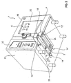
- Fig. 1 is an embodiment of a cooking appliance 1 according to the invention shown in front view that is designed in particular as a combi steamer.
- the cooking appliance has a cooking chamber 2, which is partially visible through a viewing window 22 of a cooking chamber 19.
- the cooking chamber door 19 may be attached in the usual way to the housing 21 of the cooking appliance 1 for opening and closing the cooking chamber 2.
- Fig. 1 further illustrates a visible through the viewing window 22 nozzle assembly 5, which has in the example case by the squares 15-17 symbolized nozzles.
- These nozzles 15-17 are part of a cleaning device 3 according to the invention of the cooking appliance 1, which will be described in more detail below.
- the nozzles 15-17 are fixedly mounted at suitable locations of the cooking chamber 2, so that they can wet all surfaces of the cooking chamber 2 in cooperation with the cleaning agent through the formation of a liquid cleaning spray.
- a storage container or a cartridge 18 for cleaning agent and a storage container or a cartridge 4 for rinse aid, preferably in the form of water, can be seen by the cleaning device 3, which in each case is assigned to the underside of the housing 21 Drawer guide 23 and 24 are arranged.
- the cartridges 18 and 4 can be inserted into the associated drawer slide 23 and 24 as interchangeable components, including the two cartridges engaging recesses or HandlingausEnglishept 12 and 12 ', which also in Fig. 2 are visible.
- the drawer guides are in the illustrated in the figures, particularly preferred embodiment with an in Fig. 1 each visible scaling 11 and 11 'provided.
- a simple level monitoring is possible in this way.
- Fig. 2 further clarifies that the cleaning device 3 the drawer guides 23 and 24 associated perforating 14 or 14 ', which are fixed to the device and each having Perforationsnadeln 14 a and 14 b, for example, from Fig. 3 can be seen.
- the cartridge 4 As further from a synopsis of Fig. 4 and 5 shows, the cartridge 4, as well as the similarly constructed cartridge 18, a cuboid in the exemplary case cartridge housing 29, at one end of which the aforementioned engagement recess 12 and 12 'is arranged on the underside.
- the cartridge housing 29 further has an edge recess 13, one of Fig. 6 apparent stackable storage or transport packaging in an outer packaging 30 makes possible.
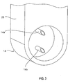
- the housing 29 At its engagement recess 12 or 12 'opposite end, the housing 29 on its underside a nozzle 28, the front side with a Fill opening 6 is provided.
- the filling opening 6 is covered by a perforable elastic membrane 7, which can be fixed by means of a cover 8 on the neck, preferably via a screw connection 10.
- the lid 8, in turn, has a through-passage 9, through which the perforation needles 14a and 14b of the perforation device 14 can pass.
- the perforation needles 14a and 14b are hollow and in fluid communication with suction conduits 26 and 27, respectively, as is understood Fig. 4 results.
- the suction lines 26 and 27 in turn lead to the nozzle assembly 5, wherein in each of the suction lines 26 and 27 an initially explained backflow preventer is arranged. Further, of course, a pumping arrangement is provided, which is not shown in the drawings, since it is not necessary for the explanation of the principles of the present invention.
- the cooking appliance 1 according to the invention is to be provided with a cartridge 18 for liquid cleaners and / or with a cartridge 4 for rinse aid, the corresponding cartridges are made of Fig. 6 apparent outer package 30 removed and according to Fig. 2 inserted into the respective drawer slide 23 and 24.
- Fig. 7 to 9 an alternative embodiment of a perforator 31 is shown. All parts with those of the embodiment according to the Fig. 1 to 6 match, are provided with the same reference numerals.
- Fig. 7 shows a sectional view of another embodiment of a perforation device 31 according to the invention.
- the perforation device 31 has a perforating needle 32, which is provided on its underside with a suction channel 33 and on its upper side with a supply air channel 34.
- the perforating needle 32 also has a fixing section 35, which is formed integrally with the perforating needle 32 at an end facing the connection port 38 and comprises two retaining projections 36, 37, which are provided with passage openings 39, 40 corresponding to the connection port 38 for forming a bayonet closure , In two circumferential grooves which are formed in the fixing section 35, two O-ring seals 41, 42 are inserted for fluid sealing between the replaceable perforating needle 32 and the connection port 38.
- connection port 38 has an intake manifold 43 for ambient air, which serves for pressure equalization, and an intake manifold 44 for supplying a liquid via the perforating needle 32.
- a sectional view of a cap 45 is shown, which has a receiving portion 47 formed therein a receiving channel 46 for the perforating needle 32 in a receiving portion 47.
- a receiving portion 47 formed therein a receiving channel 46 for the perforating needle 32 in a receiving portion 47.
- two projections 48, 49 are formed and at the opposite end of the cap 45, a handle portion 52 is formed.
- the cap 45 serves to transport safety and as an exchange tool for the perforating needle 32nd
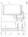
- Fig. 8 is a sectional view showing the reservoir 4; 18 and the cleaning device 3 with the perforation 31 shows, wherein the perforating needle 32 is inserted in the connection port 38.
- the perforating needle 32 passes through the lid. 8 into the passage recess 9 and perforates the membrane 7 mounted therein, which is designed here as a rubber stopper.
- Fig. 9 shows a greatly enlarged perspective view of the perforating needle 32 with the intake passage 33 formed therein and the supply air duct 34, and formed on the fixing portion 35 diametrically opposed retaining projections 36, 37.
- two end-side retaining recesses 50, 51 are formed in the fixing section 35, in which engage the projections 48, 49 of the cap 45 during assembly or replacement of the perforating needle 32.
- the perforating needle 32 can thereby be twisted or locked to form a bayonet closure with the connection port 38.
- the removal or disassembly of the perforating needle 32 is accordingly in the reverse direction.
- the in the Fig. 7 to 9 illustrated second embodiment of the perforation 31 has the advantage that the perforating needle 32 is interchangeable and with the help of the cap 50, which also serves as a transport lock, in the connection port 38 can be easily assembled and disassembled. Furthermore, the perforating needle 32 as a wear part, z. B. as an injection molded part, are made in one piece and thus cost.
Landscapes
- Chemical & Material Sciences (AREA)
- Engineering & Computer Science (AREA)
- Chemical Kinetics & Catalysis (AREA)
- Combustion & Propulsion (AREA)
- Mechanical Engineering (AREA)
- General Engineering & Computer Science (AREA)
- Cookers (AREA)
- Electric Ovens (AREA)
Applications Claiming Priority (1)
| Application Number | Priority Date | Filing Date | Title |
|---|---|---|---|
| DE102008019368 | 2008-04-17 |
Publications (2)
| Publication Number | Publication Date |
|---|---|
| EP2110606A2 true EP2110606A2 (fr) | 2009-10-21 |
| EP2110606A3 EP2110606A3 (fr) | 2011-10-05 |
Family
ID=40846129
Family Applications (1)
| Application Number | Title | Priority Date | Filing Date |
|---|---|---|---|
| EP08017495A Withdrawn EP2110606A3 (fr) | 2008-04-17 | 2008-10-06 | Appareil de cuisson industriel, en particulier amortisseur à air chaud |
Country Status (1)
| Country | Link |
|---|---|
| EP (1) | EP2110606A3 (fr) |
Cited By (8)
| Publication number | Priority date | Publication date | Assignee | Title |
|---|---|---|---|---|
| DE102012203268A1 (de) * | 2012-02-29 | 2013-08-29 | Miwe Michael Wenz Gmbh | Gargerät mit Befüllöffnung zum Einfüllen von Reinigungsflüssigkeit sowie Verfahren zum Befüllen eines Gargerätes mit Reinigungsflüssigkeit |
| WO2013088227A3 (fr) * | 2011-12-13 | 2014-01-16 | Convotherm Elektrogerate Gmbh | Cartouche de nettoyage pour appareil chauffant pour cuire des aliments et mécanisme d'ouverture de cartouche |
| ITTV20130170A1 (it) * | 2013-10-17 | 2015-04-18 | Lainox Ali Spa | "forno per la ristorazione collettiva con dispositivo di alimentazione del detergente per il sistema di lavaggio della camera di cottura" |
| DE102014008834A1 (de) * | 2014-06-20 | 2015-12-24 | Küppersbusch Großküchentechnik GmbH & Co. KG | Gar- und/oder Kochgerät |
| DE102015105937A1 (de) * | 2015-04-17 | 2016-11-03 | Rational Aktiengesellschaft | Dosierbehälter und Gargerät |
| EP3702677A1 (fr) * | 2019-02-26 | 2020-09-02 | Electrolux Professional S.p.A. | Four de cuisson comportant un générateur de vapeur |
| US12181155B2 (en) | 2019-02-26 | 2024-12-31 | Electrolux Professional S.P.A. | Cooking oven with steam generator |
| DE102024106600A1 (de) * | 2024-03-07 | 2025-09-11 | Welbilt Deutschland GmbH | Flasche zum einführen in ein küchen- und/oder gastronomiegerät, ein küchen- und/oder gastronomiegerät und eine anordnung |
Family Cites Families (3)
| Publication number | Priority date | Publication date | Assignee | Title |
|---|---|---|---|---|
| DE19961835C2 (de) * | 1999-12-21 | 2003-03-20 | Rational Ag | Verfahren sowie Vorrichtung zum automatischen Gargerätereinigen |
| WO2001051856A1 (fr) * | 2000-01-10 | 2001-07-19 | Levens Group B.V. | Procede et dispositif de nettoyage de four |
| DE10060204B4 (de) * | 2000-11-28 | 2004-04-29 | Wiesheu Gmbh | Reinigungssystem für einen Ofen und Verfahren zur Ofenreinigung |
-
2008
- 2008-10-06 EP EP08017495A patent/EP2110606A3/fr not_active Withdrawn
Non-Patent Citations (1)
| Title |
|---|
| None |
Cited By (12)
| Publication number | Priority date | Publication date | Assignee | Title |
|---|---|---|---|---|
| WO2013088227A3 (fr) * | 2011-12-13 | 2014-01-16 | Convotherm Elektrogerate Gmbh | Cartouche de nettoyage pour appareil chauffant pour cuire des aliments et mécanisme d'ouverture de cartouche |
| CN104379998A (zh) * | 2011-12-13 | 2015-02-25 | 康威瑟姆家电公司 | 用于烹饪食物的加热设备的清洁筒以及用于打开筒的机构 |
| DE102012203268A1 (de) * | 2012-02-29 | 2013-08-29 | Miwe Michael Wenz Gmbh | Gargerät mit Befüllöffnung zum Einfüllen von Reinigungsflüssigkeit sowie Verfahren zum Befüllen eines Gargerätes mit Reinigungsflüssigkeit |
| EP2634492A1 (fr) * | 2012-02-29 | 2013-09-04 | MIWE Michael Wenz GmbH | Appareil de cuisson avec ouverture de remplissage pour le liquide de nettoyage, système composé d'un récipient et d'un appareil de cuisson ainsi que procédé de remplissage d'un appareil de cuisson avec du liquide de nettoyage |
| ITTV20130170A1 (it) * | 2013-10-17 | 2015-04-18 | Lainox Ali Spa | "forno per la ristorazione collettiva con dispositivo di alimentazione del detergente per il sistema di lavaggio della camera di cottura" |
| WO2015056063A1 (fr) * | 2013-10-17 | 2015-04-23 | Lainox Ali Spa | Four pour l'industrie de la restauration avec dispositif pour envoyer le détergent au système de nettoyage de la chambre de cuisson |
| DE102014008834A1 (de) * | 2014-06-20 | 2015-12-24 | Küppersbusch Großküchentechnik GmbH & Co. KG | Gar- und/oder Kochgerät |
| DE102014008834B4 (de) * | 2014-06-20 | 2016-09-22 | Küppersbusch Großküchentechnik GmbH & Co. KG | Gar- und/oder Kochgerät |
| DE102015105937A1 (de) * | 2015-04-17 | 2016-11-03 | Rational Aktiengesellschaft | Dosierbehälter und Gargerät |
| EP3702677A1 (fr) * | 2019-02-26 | 2020-09-02 | Electrolux Professional S.p.A. | Four de cuisson comportant un générateur de vapeur |
| US12181155B2 (en) | 2019-02-26 | 2024-12-31 | Electrolux Professional S.P.A. | Cooking oven with steam generator |
| DE102024106600A1 (de) * | 2024-03-07 | 2025-09-11 | Welbilt Deutschland GmbH | Flasche zum einführen in ein küchen- und/oder gastronomiegerät, ein küchen- und/oder gastronomiegerät und eine anordnung |
Also Published As
| Publication number | Publication date |
|---|---|
| EP2110606A3 (fr) | 2011-10-05 |
Similar Documents
| Publication | Publication Date | Title |
|---|---|---|
| EP3331411B1 (fr) | Contenant pour détergent | |
| EP2110606A2 (fr) | Appareil de cuisson industriel, en particulier amortisseur à air chaud | |
| EP2237900B1 (fr) | Nettoyeur à haute pression avec un système d'approvisionnement en additif nettoyant liquide et de distribution d'un tel additif | |
| EP0711668A2 (fr) | Appareil de recharge pour cartouche d'impression par jet d'encre | |
| WO2015007329A1 (fr) | Appareil de nettoyage de surfaces dures portable | |
| DE202007019225U1 (de) | Vorrichtung zur Wiederbefüllung einer Tintenpatrone für einen Tintenstrahldrucker | |
| DE102013102263A1 (de) | Feuchtreinigungsvorrichtung, insbesondere Fensterreinigungsvorrichtung | |
| WO2000012403A1 (fr) | Dispositif pour vider des recipients remplis de liquides | |
| EP2695555A1 (fr) | Dispositif de nettoyage du système à lait dans des machines à café entièrement automatiques | |
| DE60212583T2 (de) | Haushaltsreinigungswerkzeug | |
| DE202013105808U1 (de) | Vorrichtung zur Entnahme von medizinischen Flüssigkeiten aus dafür vorgesehenen Vorratsbehältern mittels Spritzen | |
| EP0064949A1 (fr) | Fermeture de récipient permettant l'adaptation d'un dispositif de soutirage | |
| EP0504568B1 (fr) | Appareil de nettoyage à haute pression | |
| DE202014000477U1 (de) | Entnahmeeinrichtung für Flüssigkeiten | |
| EP3097829B1 (fr) | Dispositif de réception, distributeur automatique de boissons comprenant un dispositif de réception et procédé de fixation amovible d'une cartouche dans un tel dispositif de réception | |
| DE102009052029A1 (de) | Sauglanze und Behälter mit Codiergeometrie | |
| EP1533125A1 (fr) | Cartouche d'encre, unité de cartouche d'encre et tête d'impression par jet d'encre | |
| EP2858864B1 (fr) | Réservoir, logement pour réservoir, et installation de traitement pour véhicule | |
| DE202012008555U1 (de) | Reinigungsvorrichtung zur Reinigung von Spritzpistolen | |
| EP2942107A1 (fr) | Connecteur | |
| DE102012203268A1 (de) | Gargerät mit Befüllöffnung zum Einfüllen von Reinigungsflüssigkeit sowie Verfahren zum Befüllen eines Gargerätes mit Reinigungsflüssigkeit | |
| DE8605007U1 (de) | Absaugeinrichtung für Öl | |
| EP2281939B1 (fr) | Appareil ménager doté d'un distributeur | |
| EP0544072A1 (fr) | Dispositif pour la distribution et le dosage des produits de nettoyage | |
| DE102008010506A1 (de) | Verfahren und Vorrichtung zur Wiederbefüllung einer Tintenpatrone für einen Tintenstrahldrucker |
Legal Events
| Date | Code | Title | Description |
|---|---|---|---|
| PUAI | Public reference made under article 153(3) epc to a published international application that has entered the european phase |
Free format text: ORIGINAL CODE: 0009012 |
|
| AK | Designated contracting states |
Kind code of ref document: A2 Designated state(s): AT BE BG CH CY CZ DE DK EE ES FI FR GB GR HR HU IE IS IT LI LT LU LV MC MT NL NO PL PT RO SE SI SK TR |
|
| AX | Request for extension of the european patent |
Extension state: AL BA MK RS |
|
| PUAL | Search report despatched |
Free format text: ORIGINAL CODE: 0009013 |
|
| AK | Designated contracting states |
Kind code of ref document: A3 Designated state(s): AT BE BG CH CY CZ DE DK EE ES FI FR GB GR HR HU IE IS IT LI LT LU LV MC MT NL NO PL PT RO SE SI SK TR |
|
| AX | Request for extension of the european patent |
Extension state: AL BA MK RS |
|
| RIC1 | Information provided on ipc code assigned before grant |
Ipc: F24C 14/00 20060101AFI20110830BHEP |
|
| 17P | Request for examination filed |
Effective date: 20120330 |
|
| AKX | Designation fees paid |
Designated state(s): CZ DE DK ES IT |
|
| STAA | Information on the status of an ep patent application or granted ep patent |
Free format text: STATUS: THE APPLICATION IS DEEMED TO BE WITHDRAWN |
|
| 18D | Application deemed to be withdrawn |
Effective date: 20130503 |