EP2110612A2 - Four ventilé - Google Patents
Four ventilé Download PDFInfo
- Publication number
- EP2110612A2 EP2110612A2 EP09156224A EP09156224A EP2110612A2 EP 2110612 A2 EP2110612 A2 EP 2110612A2 EP 09156224 A EP09156224 A EP 09156224A EP 09156224 A EP09156224 A EP 09156224A EP 2110612 A2 EP2110612 A2 EP 2110612A2
- Authority
- EP
- European Patent Office
- Prior art keywords
- chamber
- oven
- bulkhead
- apertures
- holes
- Prior art date
- Legal status (The legal status is an assumption and is not a legal conclusion. Google has not performed a legal analysis and makes no representation as to the accuracy of the status listed.)
- Withdrawn
Links
- 235000013305 food Nutrition 0.000 claims abstract description 20
- 238000011144 upstream manufacturing Methods 0.000 claims 1
- 238000010411 cooking Methods 0.000 description 8
- 230000000694 effects Effects 0.000 description 5
- 230000003068 static effect Effects 0.000 description 3
- 229910000831 Steel Inorganic materials 0.000 description 1
- 238000005265 energy consumption Methods 0.000 description 1
- 239000012530 fluid Substances 0.000 description 1
- 230000005484 gravity Effects 0.000 description 1
- 238000010438 heat treatment Methods 0.000 description 1
- 230000001788 irregular Effects 0.000 description 1
- 239000002184 metal Substances 0.000 description 1
- 230000002093 peripheral effect Effects 0.000 description 1
- 239000010959 steel Substances 0.000 description 1
- 238000009423 ventilation Methods 0.000 description 1
Images



Classifications
-
- F—MECHANICAL ENGINEERING; LIGHTING; HEATING; WEAPONS; BLASTING
- F24—HEATING; RANGES; VENTILATING
- F24C—DOMESTIC STOVES OR RANGES ; DETAILS OF DOMESTIC STOVES OR RANGES, OF GENERAL APPLICATION
- F24C15/00—Details
- F24C15/32—Arrangements of ducts for hot gases, e.g. in or around baking ovens
- F24C15/322—Arrangements of ducts for hot gases, e.g. in or around baking ovens with forced circulation
- F24C15/325—Arrangements of ducts for hot gases, e.g. in or around baking ovens with forced circulation electrically-heated
Definitions
- the present invention relates to a ventilated oven according to the preamble of claim 1.
- a ventilated oven additionally includes a fan that draws air from the chamber and conveys it into an interspace behind the chamber, where the air laps the electric resistor and becomes hot. The hot air flow generated by the fan is then directed back into the chamber through slots provided in the bulkhead that separates the chamber from the interspace.
- ventilated ovens offer the advantage that the air circulation generated by the fan provides a uniform hot air distribution within the chamber.
- ventilated ovens actually improve the distribution of the hot air flow, it has been observed in practice that often said distribution is not uniform enough to ensure proper cooking of foods arranged together at different levels in the chamber: for example, if three dripping pans are placed into the chamber at different heights, it has been observed that the foods contained therein cook differently; more in particular, experimental tests have shown that the food placed in the highest dripping pan cooks more quickly than the others, whereas the food contained in the dripping pan which is closest to the fan grid is the slowest to cook.
- the oven described in said patent has a chamber that can be subdivided into two parts by means of a dividing septum, and a rear bulkhead with holes distributed asymmetrically on two adjacent sides thereof (the top and left sides); the oven also features additional outlets arranged immediately under the bulkhead centre and used in the absence of the dividing septum.
- this oven still suffers from a few drawbacks: due to an excessively asymmetrical distribution of the hot air flow and to the fact that when the septum is in place the hot air hits the foods from two sides only (from the top and from the left), the resulting hot air distribution in the chamber is not optimal.
- the additional slots located immediately under the bulkhead centre heat the foods excessively in the adjacent area, while any food being laid to cook on the chamber bottom is not heated appropriately, resulting in improper cooking.
- the present invention aims at solving these and other problems suffered by the ventilated ovens known in the art.
- the present invention is based on the idea of generating a differentiated air flow in the oven chamber along the whole perimeter of the rear bulkhead of the chamber itself.
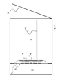
- a ventilated oven 1 that comprises a chamber 2 closed by a door 3, in which three dripping pans 4A, 4B and 4C have been placed; the side of the chamber 2 opposite to the door is closed by a bulkhead 5, a plan view of which is shown in Fig. 2 .
- interspace 6 On the side of the bulkhead 5 opposite to the door 3 there is an interspace 6, which is closed at the rear by a wall 15 and on which the fan 7 and the electric resistor 8 are arranged.
- the interspace 6 communicates with the chamber 2 by means of the grid 10 shown in Fig. 2 , through which the fan 7 draws air from the chamber 2 and directs an air flow against the resistor 8 (normally circular in shape), which heats said air flow.
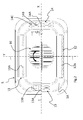
- Fig. 7 it schematically shows the direction of the air flow within the interspace 6: the fan 7 generates an air flow 16 which is concordant with the direction of rotation of the fan itself; as shown in the illustrated example, both the fan 7 and the air flow 16 circulating within the interspace 5 rotate clockwise.
- the direction of rotation of the fan is of little importance; as a matter of fact, the air flow 16 may be either concordant with or discordant from (whether clockwise or counterclockwise) the direction of rotation of the fan depending on the type of blades fitted to the fan; all the attention should be focused, as will be discussed hereafter, on the direction of rotation of the air flow within the interspace 6.
- the dashed lines outline the sets of outlet holes 11, 12, 13 and 14 as arranged on the bulkhead 5.
- a first advantageous feature can be found in the fact that said bulkhead 5 is preferably a plate, in particular a metal plate, and that the various sets of holes are distributed asymmetrically and discontinuously along the perimetric edge 5A of the bulkhead 5; the total areas of at least one pair of sets of holes adjacent to opposite sides of the bulkhead are different.
- total area refers to the sum of all the areas of the single holes adjacent to one side of the bulkhead 5.
- the air passage area obtained by summing up the areas of all the upper holes 11 is different from that of the lower holes 12, and the air passage area obtained by summing up the areas of all the left-hand side holes 13 is different from that of the right-hand side holes 14.
- the perimetric edge 5A where the apertures are provided is inclined relative to the bottom plane 5B of the bulkhead 5; it thus creates an inclined perimetric annular band that extends around the bottom 5B of the bulkhead 5, which includes the aperture 10 for letting the air flow towards the fan.
- said edge 5A is continuous or discontinuous, provided that the outlet section of the apertures (or sets of holes) is inclined relative to the plane of the bulkhead 5: in the latter case, in fact, it will suffice that the perimetric edge 5A includes inclined portions where the holes are provided.
- the perimetric edge 5A is inclined in a manner such that the convex side of the bulkhead 5 faces the oven chamber 2 and the concave side thereof faces the interspace 6: this causes the air flow exiting the holes to be directed first towards the chamber walls, not directly onto the foods, and more in particular it allows the fan and the resistor to be installed within the interspace 6 without requiring additional room.
- This feature improves the air flow circulation in the chamber 2.
- the extremely hot air exiting through the sets of holes 11,12,13,14 is directed towards the side walls of the chamber 2, and then it propagates towards the centre of the chamber 2. After having lapped the foods, the air flow is drawn back to the fan through the grid 10.
- the air flow exiting the holes is therefore directed first towards the walls of the chamber 2 and only in a second time towards the foods.
- the total area of the right-hand side set of holes 14 is about half the total area of the left-hand side set of holes 13.
- a further advantageous feature consists in the use of a combination of circular holes 11A, 12A, 13A and 14A, long slotted holes 13B, 14B, and short slotted holes 14C.
- the four sets of holes 11, 12, 13 and 14 are provided by adopting four different solutions: the upper set of holes 11 consists of a first row of four holes close together and a second row of four holes close together located at a distance from the first row, the holes 11A of both rows being all circular in shape.
- the opposite lower set of holes 12 also consists of circular holes 12A arranged in one row.
- the two lateral sets of holes 13 and 14 consist of two side-by-side rows comprising circular holes 13A, 14A as well as long slotted holes 13B, 14B.
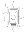
- the sets of holes may be replaced with single apertures, so long as the above-described area asymmetry is observed, as in the example shown in Fig. 8 , wherein by way of example the holes 11,12,13,14 have been replaced with equivalent rectangular apertures 110,120,130 and 140, to which the above considerations still apply.
- the only difference is that for the apertures 110 and 120 the total area is simply the area of the single aperture, while for the side apertures 130 and 140 the total area is the sum of the areas of the two apertures.
- the apertures 110,120,130 and 140 are provided on the peripheral edge 5A of the bulkhead 5, which is inclined relative to the plane in which the bulkhead 5 lies, coinciding with the plane 5B that represents the central portion of the bulkhead.
- the bulkhead 5 has been described above in combination with an oven 1 according to a basic configuration, it may be installed into any type of ventilated oven for providing the aforementioned effects and for obtaining the resulting advantages in multilevel cooking, which is made possible by the uniform temperature achieved in the chamber.
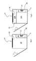
- a particular type of oven in which the bulkhead 5 exerts particularly advantageous effects is the one shown in Figs. 5 and 6 in two different operating conditions.
- this oven 10 just like the oven 1, comprises a fan 70, an electric resistor 80 adapted to heat the air drawn by the fan 70, and a bulkhead 5 like the one described above, which separates a chamber 20 from an interspace 60 wherein the air drawn by the fan circulates before returning into the chamber 20 through the holes provided in the bulkhead 5, which is arranged behind the chamber 20 in the area opposite to the door 3.
- the oven 10 also comprises an upper electric resistor 81 mounted to the ceiling of the chamber 20, which is normally used for the so-called "GRILL" cooking.
- the chamber 20 can be subdivided into two chambers 20A (lower) and 20B (upper) by means of a removable septum 40, which is inserted into the chamber 20 at a predefined height; more in particular, it has been observed that the best effects on the cooking of foods are obtained when the removable septum 40 is positioned at a height such that the volume of the upper chamber 20B is one third of the total volume of the chamber 20.
- the bulkhead 5 extends from the bottom of the chamber 20 up to a point where it meets the removable septum 40; therefore, in the illustrated preferred configuration the height thereof is equal to approximately two thirds of the total height of the chamber 20.
- Figs. 5 and 6 show two different operating modes of the oven 10: in Fig. 5 the septum 40 is absent and the whole inner chamber 20 is affected by the circulating air drawn by the fan 70, heated by the resistor 80 and circulated through the holes 11,12,13,14 in the bulkhead 5.
- the resulting situation is thus essentially similar to the one described previously, the only difference being that in this case the fan 70 is not placed in the middle of the chamber 20, but it has been moved downwards, thereby further improving the distribution of the air flow, thanks to greater turbulences, for the purpose of achieving a more uniform air distribution in the chamber 20; in this regard, the upper electric resistor 81 may be turned on or off as desired by the user.
- the removable septum 40 in use is insulated (or anyway that it is quite thick, if made of steel, so as to limit the thermal exchange between the two chambers 20A and 20B), and that the upper resistor 81 is off, the operation of the oven will be limited to the lower chamber 20A only, which is useful, for example, when the foods to be cooked are just a few and therefore it is not economically advisable to use the whole volume of the chamber 20, thus saving some energy.
- the configuration of the oven 10 shown in Fig. 6 offers the big advantage that two chambers 20A and 20B are made available to the user, who can decide to use them either simultaneously or separately, according to the type of foods to be cooked.
- the removable septum 40 allows to keep the chambers 20A and 20B at different temperatures (the maximum temperature difference being approximately 100°C).
- the fan grid 10 may be replaced with any other suitable aperture, such as a simple hole or the like.
- the present invention is advantageously applicable to ovens having a capacity of over 60 litres, preferably of approximately 70 litres, which can be embedded into a recess having a width of 60 cm and a height of 60 cm: when applied to such ovens, the present invention in fact allows to obtain a temperature distribution within the chamber 20 such as to ensure the simultaneous cooking of foods arranged at four levels (i.e. in four dripping pans). It is apparent from the above that the present invention also offers a considerable advantage in terms of energy consumption, since it allows a larger number of foods to be cooked simultaneously in a single cooking cycle.
Landscapes
- Engineering & Computer Science (AREA)
- Chemical & Material Sciences (AREA)
- Combustion & Propulsion (AREA)
- Mechanical Engineering (AREA)
- General Engineering & Computer Science (AREA)
- Electric Stoves And Ranges (AREA)
- Crystals, And After-Treatments Of Crystals (AREA)
- Glass Compositions (AREA)
- Mechanical Treatment Of Semiconductor (AREA)
Applications Claiming Priority (1)
| Application Number | Priority Date | Filing Date | Title |
|---|---|---|---|
| ITTO20080296 ITTO20080296A1 (it) | 2008-04-15 | 2008-04-15 | Forno ventilato |
Publications (2)
| Publication Number | Publication Date |
|---|---|
| EP2110612A2 true EP2110612A2 (fr) | 2009-10-21 |
| EP2110612A3 EP2110612A3 (fr) | 2012-09-05 |
Family
ID=40297311
Family Applications (1)
| Application Number | Title | Priority Date | Filing Date |
|---|---|---|---|
| EP09156224A Withdrawn EP2110612A3 (fr) | 2008-04-15 | 2009-03-25 | Four ventilé |
Country Status (2)
| Country | Link |
|---|---|
| EP (1) | EP2110612A3 (fr) |
| IT (1) | ITTO20080296A1 (fr) |
Cited By (5)
| Publication number | Priority date | Publication date | Assignee | Title |
|---|---|---|---|---|
| WO2018102082A1 (fr) * | 2016-11-30 | 2018-06-07 | Illinois Tool Works Inc. | Système de convection destiné à être utilisé avec un four rf |
| EP3546832A1 (fr) * | 2018-03-27 | 2019-10-02 | Steel S.R.L. | Four de cuisine à alimentation hybride |
| CN111096686A (zh) * | 2018-10-25 | 2020-05-05 | 宁波方太厨具有限公司 | 一种嵌入式烤箱 |
| CN117297349A (zh) * | 2022-06-22 | 2023-12-29 | 广东美的厨房电器制造有限公司 | 热风罩和蒸烤箱 |
| CN117297348A (zh) * | 2022-06-22 | 2023-12-29 | 广东美的厨房电器制造有限公司 | 热风罩和微波烤箱 |
Citations (1)
| Publication number | Priority date | Publication date | Assignee | Title |
|---|---|---|---|---|
| EP0641976A1 (fr) | 1993-09-04 | 1995-03-08 | AEG Hausgeräte GmbH | Four électrique pour cuire au four et rotir |
Family Cites Families (8)
| Publication number | Priority date | Publication date | Assignee | Title |
|---|---|---|---|---|
| GB1309078A (en) * | 1969-06-12 | 1973-03-07 | Everson Sons Ltd G R | Ovens |
| DE2950946C2 (de) * | 1979-12-18 | 1984-08-09 | Bosch-Siemens Hausgeräte GmbH, 7000 Stuttgart | Backofen mit Umluftgebläse und Grillheizkörper |
| GB8802575D0 (en) * | 1988-02-05 | 1988-03-02 | Microwave Ovens Ltd | Microwave ovens & methods of defrosting food therein |
| FR2637053B1 (fr) * | 1988-09-29 | 1990-11-16 | Scholtes Ets Eugen | Four de cuisson mixte |
| DE4224797C2 (de) * | 1992-07-27 | 1994-09-01 | Bosch Siemens Hausgeraete | Backofen |
| DE4304524C2 (de) * | 1993-02-15 | 2002-01-24 | Bsh Bosch Siemens Hausgeraete | Backofen |
| JP2004093092A (ja) * | 2002-09-04 | 2004-03-25 | Toshiba Corp | 加熱調理器 |
| KR101106636B1 (ko) * | 2005-06-10 | 2012-01-18 | 삼성전자주식회사 | 오븐 |
-
2008
- 2008-04-15 IT ITTO20080296 patent/ITTO20080296A1/it unknown
-
2009
- 2009-03-25 EP EP09156224A patent/EP2110612A3/fr not_active Withdrawn
Patent Citations (1)
| Publication number | Priority date | Publication date | Assignee | Title |
|---|---|---|---|---|
| EP0641976A1 (fr) | 1993-09-04 | 1995-03-08 | AEG Hausgeräte GmbH | Four électrique pour cuire au four et rotir |
Cited By (8)
| Publication number | Priority date | Publication date | Assignee | Title |
|---|---|---|---|---|
| WO2018102082A1 (fr) * | 2016-11-30 | 2018-06-07 | Illinois Tool Works Inc. | Système de convection destiné à être utilisé avec un four rf |
| CN110313217A (zh) * | 2016-11-30 | 2019-10-08 | 伊利诺斯工具制品有限公司 | 用于射频烤箱的对流系统 |
| CN110313217B (zh) * | 2016-11-30 | 2022-06-24 | 伊利诺斯工具制品有限公司 | 用于射频烤箱的对流系统 |
| US11388787B2 (en) | 2016-11-30 | 2022-07-12 | Illinois Tool Works Inc. | Convection system for employment with an RF oven |
| EP3546832A1 (fr) * | 2018-03-27 | 2019-10-02 | Steel S.R.L. | Four de cuisine à alimentation hybride |
| CN111096686A (zh) * | 2018-10-25 | 2020-05-05 | 宁波方太厨具有限公司 | 一种嵌入式烤箱 |
| CN117297349A (zh) * | 2022-06-22 | 2023-12-29 | 广东美的厨房电器制造有限公司 | 热风罩和蒸烤箱 |
| CN117297348A (zh) * | 2022-06-22 | 2023-12-29 | 广东美的厨房电器制造有限公司 | 热风罩和微波烤箱 |
Also Published As
| Publication number | Publication date |
|---|---|
| ITTO20080296A1 (it) | 2009-10-16 |
| EP2110612A3 (fr) | 2012-09-05 |
Similar Documents
| Publication | Publication Date | Title |
|---|---|---|
| RU2660074C2 (ru) | Сковорода для воздушной жаровни | |
| US8113191B2 (en) | Flame tamers and arrangement thereof for barbeque grills | |
| CN102216690B (zh) | 具有双风扇对流性能分配器的烤炉 | |
| EP2110612A2 (fr) | Four ventilé | |
| CN108720650B (zh) | 一种食物烹调设备 | |
| KR101207641B1 (ko) | 가열조리기 | |
| WO2006025133A1 (fr) | Dispositif de cuisson par chauffage | |
| CN108095567A (zh) | 烹饪器具 | |
| WO2012062679A1 (fr) | Four à convection forcée | |
| EP3425286B1 (fr) | Dispositif de cuisson et son procédé de fonctionnement | |
| CN216907658U (zh) | 空气炸锅 | |
| CN218870095U (zh) | 烹饪器具 | |
| KR20160082349A (ko) | 직화구이 스팀 불판 | |
| EP3770511B1 (fr) | Four de cuisson électrique à convection | |
| CN216907657U (zh) | 空气炸锅 | |
| JP5377133B2 (ja) | 加熱調理器 | |
| JP5377132B2 (ja) | 加熱調理器 | |
| CN216907659U (zh) | 空气炸锅 | |
| EP2301397A1 (fr) | Réducteur de flammes et agencement associé pour les grills de barbecue | |
| KR20040071022A (ko) | 조리장치 | |
| EP1739362A2 (fr) | Four ménager avec système de circulation d'air | |
| CN224193320U (zh) | 烹饪器具 | |
| JP6423479B2 (ja) | 調理用電気加熱器 | |
| CN216293752U (zh) | 一种蒸烤内胆结构及蒸烤一体机 | |
| CN224112515U (zh) | 一种均匀加热的风道挡板结构 |
Legal Events
| Date | Code | Title | Description |
|---|---|---|---|
| PUAI | Public reference made under article 153(3) epc to a published international application that has entered the european phase |
Free format text: ORIGINAL CODE: 0009012 |
|
| AK | Designated contracting states |
Kind code of ref document: A2 Designated state(s): AT BE BG CH CY CZ DE DK EE ES FI FR GB GR HR HU IE IS IT LI LT LU LV MC MK MT NL NO PL PT RO SE SI SK TR |
|
| AX | Request for extension of the european patent |
Extension state: AL BA RS |
|
| PUAL | Search report despatched |
Free format text: ORIGINAL CODE: 0009013 |
|
| AK | Designated contracting states |
Kind code of ref document: A3 Designated state(s): AT BE BG CH CY CZ DE DK EE ES FI FR GB GR HR HU IE IS IT LI LT LU LV MC MK MT NL NO PL PT RO SE SI SK TR |
|
| AX | Request for extension of the european patent |
Extension state: AL BA RS |
|
| RIC1 | Information provided on ipc code assigned before grant |
Ipc: F24C 15/32 20060101AFI20120802BHEP |
|
| STAA | Information on the status of an ep patent application or granted ep patent |
Free format text: STATUS: THE APPLICATION IS DEEMED TO BE WITHDRAWN |
|
| 18D | Application deemed to be withdrawn |
Effective date: 20121002 |