EP2110620A1 - Vierwegeventil - Google Patents
Vierwegeventil Download PDFInfo
- Publication number
- EP2110620A1 EP2110620A1 EP08154638A EP08154638A EP2110620A1 EP 2110620 A1 EP2110620 A1 EP 2110620A1 EP 08154638 A EP08154638 A EP 08154638A EP 08154638 A EP08154638 A EP 08154638A EP 2110620 A1 EP2110620 A1 EP 2110620A1
- Authority
- EP
- European Patent Office
- Prior art keywords
- pass
- port
- valving element
- shutoff
- chamber
- Prior art date
- Legal status (The legal status is an assumption and is not a legal conclusion. Google has not performed a legal analysis and makes no representation as to the accuracy of the status listed.)
- Granted
Links
- 239000007788 liquid Substances 0.000 claims abstract description 30
- 230000001105 regulatory effect Effects 0.000 claims abstract description 8
- 238000011144 upstream manufacturing Methods 0.000 claims description 14
- 230000009471 action Effects 0.000 claims description 2
- 230000001276 controlling effect Effects 0.000 claims description 2
- XLYOFNOQVPJJNP-UHFFFAOYSA-N water Substances O XLYOFNOQVPJJNP-UHFFFAOYSA-N 0.000 description 10
- 238000001914 filtration Methods 0.000 description 5
- 238000009529 body temperature measurement Methods 0.000 description 4
- LYCAIKOWRPUZTN-UHFFFAOYSA-N Ethylene glycol Chemical compound OCCO LYCAIKOWRPUZTN-UHFFFAOYSA-N 0.000 description 2
- 238000010438 heat treatment Methods 0.000 description 2
- 241001465805 Nymphalidae Species 0.000 description 1
- 230000002528 anti-freeze Effects 0.000 description 1
- 230000008901 benefit Effects 0.000 description 1
- 238000012790 confirmation Methods 0.000 description 1
- 238000001816 cooling Methods 0.000 description 1
- 230000002349 favourable effect Effects 0.000 description 1
- WGCNASOHLSPBMP-UHFFFAOYSA-N hydroxyacetaldehyde Natural products OCC=O WGCNASOHLSPBMP-UHFFFAOYSA-N 0.000 description 1
- 238000004519 manufacturing process Methods 0.000 description 1
- 238000005259 measurement Methods 0.000 description 1
- 230000007246 mechanism Effects 0.000 description 1
- 230000009467 reduction Effects 0.000 description 1
- 239000000523 sample Substances 0.000 description 1
- 239000000126 substance Substances 0.000 description 1
Images


Classifications
-
- F—MECHANICAL ENGINEERING; LIGHTING; HEATING; WEAPONS; BLASTING
- F16—ENGINEERING ELEMENTS AND UNITS; GENERAL MEASURES FOR PRODUCING AND MAINTAINING EFFECTIVE FUNCTIONING OF MACHINES OR INSTALLATIONS; THERMAL INSULATION IN GENERAL
- F16K—VALVES; TAPS; COCKS; ACTUATING-FLOATS; DEVICES FOR VENTING OR AERATING
- F16K11/00—Multiple-way valves, e.g. mixing valves; Pipe fittings incorporating such valves
- F16K11/02—Multiple-way valves, e.g. mixing valves; Pipe fittings incorporating such valves with all movable sealing faces moving as one unit
-
- F—MECHANICAL ENGINEERING; LIGHTING; HEATING; WEAPONS; BLASTING
- F16—ENGINEERING ELEMENTS AND UNITS; GENERAL MEASURES FOR PRODUCING AND MAINTAINING EFFECTIVE FUNCTIONING OF MACHINES OR INSTALLATIONS; THERMAL INSULATION IN GENERAL
- F16K—VALVES; TAPS; COCKS; ACTUATING-FLOATS; DEVICES FOR VENTING OR AERATING
- F16K11/00—Multiple-way valves, e.g. mixing valves; Pipe fittings incorporating such valves
- F16K11/02—Multiple-way valves, e.g. mixing valves; Pipe fittings incorporating such valves with all movable sealing faces moving as one unit
- F16K11/04—Multiple-way valves, e.g. mixing valves; Pipe fittings incorporating such valves with all movable sealing faces moving as one unit comprising only lift valves
- F16K11/044—Multiple-way valves, e.g. mixing valves; Pipe fittings incorporating such valves with all movable sealing faces moving as one unit comprising only lift valves with movable valve members positioned between valve seats
-
- F—MECHANICAL ENGINEERING; LIGHTING; HEATING; WEAPONS; BLASTING
- F24—HEATING; RANGES; VENTILATING
- F24D—DOMESTIC- OR SPACE-HEATING SYSTEMS, e.g. CENTRAL HEATING SYSTEMS; DOMESTIC HOT-WATER SUPPLY SYSTEMS; ELEMENTS OR COMPONENTS THEREFOR
- F24D19/00—Details
- F24D19/10—Arrangement or mounting of control or safety devices
- F24D19/1006—Arrangement or mounting of control or safety devices for water heating systems
- F24D19/1009—Arrangement or mounting of control or safety devices for water heating systems for central heating
- F24D19/1015—Arrangement or mounting of control or safety devices for water heating systems for central heating using a valve or valves
- F24D19/1021—Arrangement or mounting of control or safety devices for water heating systems for central heating using a valve or valves a by pass valve
-
- F—MECHANICAL ENGINEERING; LIGHTING; HEATING; WEAPONS; BLASTING
- F24—HEATING; RANGES; VENTILATING
- F24D—DOMESTIC- OR SPACE-HEATING SYSTEMS, e.g. CENTRAL HEATING SYSTEMS; DOMESTIC HOT-WATER SUPPLY SYSTEMS; ELEMENTS OR COMPONENTS THEREFOR
- F24D19/00—Details
- F24D19/10—Arrangement or mounting of control or safety devices
- F24D19/1006—Arrangement or mounting of control or safety devices for water heating systems
- F24D19/1009—Arrangement or mounting of control or safety devices for water heating systems for central heating
- F24D19/1015—Arrangement or mounting of control or safety devices for water heating systems for central heating using a valve or valves
- F24D19/1024—Arrangement or mounting of control or safety devices for water heating systems for central heating using a valve or valves a multiple way valve
-
- F—MECHANICAL ENGINEERING; LIGHTING; HEATING; WEAPONS; BLASTING
- F24—HEATING; RANGES; VENTILATING
- F24D—DOMESTIC- OR SPACE-HEATING SYSTEMS, e.g. CENTRAL HEATING SYSTEMS; DOMESTIC HOT-WATER SUPPLY SYSTEMS; ELEMENTS OR COMPONENTS THEREFOR
- F24D3/00—Hot-water central heating systems
- F24D3/10—Feed-line arrangements, e.g. providing for heat-accumulator tanks, expansion tanks ; Hydraulic components of a central heating system
Definitions
- the present invention relates to a four-way valve for distributing and controlling a liquid to the individual user appliance, from which the liquid normally returns at a different temperature.
- four-way valves are used for interposing between the delivery and return columns (particularly of a boiler) and the circuits feeding the user appliances (in particular radiators and/or sanitary appliances), including for the purples of calculating the consumption of hot and cold water by the individual user appliances (particularly in a condominium).
- a valve of this type is described in EP 1895245A2 and is provided with a body having an upstream face, a downstream face and a lateral surface which joins the upstream face to the downstream face.
- the body comprises:
- the delivery branch also comprises:
- the return branch also comprises:
- Another object is therefore to provide a valve of said type which is not subject to hydraulic unbalances caused by the fact that the by-pass valve has been inadvertently left closed.
- a further drawback is due to the fact that in the embodiment of said valve represented in Figures 1-3 of EP1895245A2 both the by-pass valve and the balancing valve, once set by authorized personnel, can be easily tampered with by anybody, which can create problems for the entire plant.
- a further object of the invention is therefore to make it impossible for a non-authorized person to easily alter the setting of this valve.
- valve of the present invention can be disposed directly in the by-pass chamber, with the advantage of not having to provide a specific filtration chamber (this substantially reducing the length of the delivery branch).
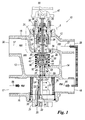
- the valve 10 represented therein comprises a body 12 having a upstream face 13, a downstream face 14 and a lateral surface which connects the upstream face 13 to the downstream face 14 and, in the specific illustrated case, comprises an upper face 15 and a lower face 16.
- a delivery branch RM for the liquid - hot or cold, depending on the use (heating or cooling) - originating from the plant delivery column
- a return branch RR for conveying to the plant return column the liquid originating from the user appliance (the temperature of the return liquid being lower or higher than the delivery temperature depending, as stated, on the use).
- the delivery branch RM comprises an inlet port 17 provided in the upstream face 13 of the body 12 and an outlet port 18 provided in the downstream face 14, the two ports 17 and 18 being, in this specific case, coaxial.
- a by-pass chamber 19 open to the outside via a threaded aperture 20 provided in the lower face 16 of the body 12.
- This aperture 20 is closed by a first threaded plug 21 screwed into the aperture 20 and hence also removable.
- the first plug 21 presents in its turn a threaded aperture 22 to house the valving element 23 of a by-pass valve.
- This valving element 23 can be screwed into the second aperture 22 such as to be able to approach to a greater or lesser extent a relative seat 24 which together with the valving element 23 forms a by-pass valve.
- the position of the by-pass valving element 23 is regulated by a simple socket spanner which engages in a coaxial hexagonal cavity 28 provided in the lower end of the valving element 23.
- valve 10 the by-pass valving element 23 is prevented from abutting against the by-pass seat 24, so that the by-pass port 27, defined by the seat 24, always connects the delivery branch RM to the return branch RR. This has been specifically required to prevent, should the personnel concerned forget to regulate the by-pass valve, that this latter remains closed, causing hydraulic unbalances in the plant due to an excessive increase in upstream pressure.
- valve 10 does not comprise a specific filtration chamber as in the case of the valve according to EP1772677A2 . It has already been stated that if it is considered necessary to provide filtration of the liquid to be fed to the user appliance, a filter 26 of cylindrical surface can be easily inserted into the by-pass chamber 19 (as can be seen from Figure 1 ). It will be apparent from that figure that the filter 26 can be replaced by simply unscrewing the plug 21 without altering the already determined by-pass setting.
- the return branch RR also comprises an inlet port 29 provided in the downstream face 14 of the body 12 and an outlet port 30 provided in the upstream face 13, the ports 29 and 30 being, in the specific illustrated case, coaxial with the common axis 57 parallel to the common axis 56 of the ports 17 and 18 of the delivery branch RM.
- the inlet port 29 communicates directly with a pre-regulation chamber 58 open to the outside via an aperture 31 provided in the upper face 15 of the body 12 and closable by a threaded plug 32 arranged to receive pre-regulation means comprising a pre-regulation ring nut 33 vertically movable in the two directions by a mechanism comprising a coaxial hollow pin 34 rotatably fixed to the plug 32 and having its upper end 35 shaped as a hexagon and engagable with a suitable tool able to rotate the pin 34 about its axis.
- the lower end 36 of the hollow pin is also shaped as a hexagon to mate with the coaxial hexagonal inner cavity 60 of the ring nut 33, this latter being externally threaded to screw into the plug 32.
- shutoff valving element 40 In the outlet chamber 38 a shutoff valving element 40 is present provided with a conical head 41 partially insertable, by screwing, into the threaded coaxial cylindrical cavity 43 provided in the stem 42 of the valving element 40 to hence be able to regulate the relative position of the direction of the axis 55.
- the shutoff valving element 40 can move vertically overall in the two directions by virtue of a cylindrical guide 44 fixed to the body 12.
- shutoff valving element 40 also presents a downwardly projecting coaxial stub 45, acting as a shutoff element for closing the by-pass port 27 when the shutoff valving element 40 is in its open position ( Figure 1 ).
- the shutoff valving element 40 is normally maintained in its position abutting against the shutoff seat 39 by the helical spring 46, but can be brought into its open position by the intervention of a conventional actuator 47 (shown only partly in Figure 1 ) disposed outside the body 12 and more precisely applied to the plug 32.
- the actuator 47 is arranged to downwardly thrust a cylindrical shaft 48 disposed coaxially within the hollow pin 34, its lower end coming into contact with the bottom of the cylindrical coaxial cavity 43 provided in the stem 42 of the shutoff valving element 40.
- a cylindrical shaft 48 disposed coaxially within the hollow pin 34, its lower end coming into contact with the bottom of the cylindrical coaxial cavity 43 provided in the stem 42 of the shutoff valving element 40.
- the presence of the compensation chamber 53 in addition to the spring 46 ensures the differential seal between the pre-regulation chamber 58 and the outlet chamber 38.
- the reduction in the thrust exerted by the actuator 47 results in a lower production cost and a saving in operating energy compared with the actuator of the valve described in EP1895245A2 .
- valve 10 in order to be able to vary the position of the pre-regulation ring nut 33 and hence vary the liquid flow rate through the return branch RR, the actuator 47 must be removed. This makes tampering much more difficult by non-authorized personnel aimed at altering the liquid flow rate through the return branch RR (in contrast to the four-way valve described in EP1895245A2 , in which the balancing valve can be easily tampered with by anybody).
- liquid concerned is normally water, possibly with antifreeze substances (for example glycol) added.
- antifreeze substances for example glycol
Landscapes
- Engineering & Computer Science (AREA)
- General Engineering & Computer Science (AREA)
- Mechanical Engineering (AREA)
- Physics & Mathematics (AREA)
- Thermal Sciences (AREA)
- Chemical & Material Sciences (AREA)
- Combustion & Propulsion (AREA)
- Lift Valve (AREA)
- Superconductors And Manufacturing Methods Therefor (AREA)
- Vehicle Body Suspensions (AREA)
- Multiple-Way Valves (AREA)
Priority Applications (3)
| Application Number | Priority Date | Filing Date | Title |
|---|---|---|---|
| DE602008000978T DE602008000978D1 (de) | 2008-04-16 | 2008-04-16 | Vierwegeventil |
| AT08154638T ATE463704T1 (de) | 2008-04-16 | 2008-04-16 | Vierwegeventil |
| EP08154638A EP2110620B1 (de) | 2008-04-16 | 2008-04-16 | Vierwegeventil |
Applications Claiming Priority (1)
| Application Number | Priority Date | Filing Date | Title |
|---|---|---|---|
| EP08154638A EP2110620B1 (de) | 2008-04-16 | 2008-04-16 | Vierwegeventil |
Publications (2)
| Publication Number | Publication Date |
|---|---|
| EP2110620A1 true EP2110620A1 (de) | 2009-10-21 |
| EP2110620B1 EP2110620B1 (de) | 2010-04-07 |
Family
ID=40251857
Family Applications (1)
| Application Number | Title | Priority Date | Filing Date |
|---|---|---|---|
| EP08154638A Not-in-force EP2110620B1 (de) | 2008-04-16 | 2008-04-16 | Vierwegeventil |
Country Status (3)
| Country | Link |
|---|---|
| EP (1) | EP2110620B1 (de) |
| AT (1) | ATE463704T1 (de) |
| DE (1) | DE602008000978D1 (de) |
Cited By (2)
| Publication number | Priority date | Publication date | Assignee | Title |
|---|---|---|---|---|
| CN105782508A (zh) * | 2014-12-22 | 2016-07-20 | Vir里齐奥工程师阀门工业股份公司 | 旁通阀 |
| GB2553807A (en) * | 2016-09-15 | 2018-03-21 | Stewan Kukard Gideon | Central Heating Filter |
Citations (4)
| Publication number | Priority date | Publication date | Assignee | Title |
|---|---|---|---|---|
| WO1994018509A1 (de) * | 1993-02-05 | 1994-08-18 | Herz Armaturen Aktiengesellschaft | Adapterarmatur zum wahlweisen anschluss eines heizkörpers |
| DE19837012A1 (de) * | 1998-08-14 | 2000-02-24 | Honeywell Ag | Armatur für den Anschluß eines Wärmetauschers |
| EP1772677A2 (de) | 2005-10-07 | 2007-04-11 | WATTS INDUSTRIES ITALIA S.r.l. | Monoblockteil für ein Multifunktionsventil und Monoblock-Multifunktionsventil zum Beaufschlagen und Steuern eines Fluids für Plattenheizkörper |
| EP1895245A2 (de) | 2006-08-31 | 2008-03-05 | Watts Industries Italia S.r.l. | Einteiliges Multifunktionsventil zum Zuführen und Steuern einer Flüssigkeit für Benutzergeräte wie Heizvorrichtungen und dergleichen |
-
2008
- 2008-04-16 AT AT08154638T patent/ATE463704T1/de not_active IP Right Cessation
- 2008-04-16 DE DE602008000978T patent/DE602008000978D1/de active Active
- 2008-04-16 EP EP08154638A patent/EP2110620B1/de not_active Not-in-force
Patent Citations (4)
| Publication number | Priority date | Publication date | Assignee | Title |
|---|---|---|---|---|
| WO1994018509A1 (de) * | 1993-02-05 | 1994-08-18 | Herz Armaturen Aktiengesellschaft | Adapterarmatur zum wahlweisen anschluss eines heizkörpers |
| DE19837012A1 (de) * | 1998-08-14 | 2000-02-24 | Honeywell Ag | Armatur für den Anschluß eines Wärmetauschers |
| EP1772677A2 (de) | 2005-10-07 | 2007-04-11 | WATTS INDUSTRIES ITALIA S.r.l. | Monoblockteil für ein Multifunktionsventil und Monoblock-Multifunktionsventil zum Beaufschlagen und Steuern eines Fluids für Plattenheizkörper |
| EP1895245A2 (de) | 2006-08-31 | 2008-03-05 | Watts Industries Italia S.r.l. | Einteiliges Multifunktionsventil zum Zuführen und Steuern einer Flüssigkeit für Benutzergeräte wie Heizvorrichtungen und dergleichen |
Cited By (2)
| Publication number | Priority date | Publication date | Assignee | Title |
|---|---|---|---|---|
| CN105782508A (zh) * | 2014-12-22 | 2016-07-20 | Vir里齐奥工程师阀门工业股份公司 | 旁通阀 |
| GB2553807A (en) * | 2016-09-15 | 2018-03-21 | Stewan Kukard Gideon | Central Heating Filter |
Also Published As
| Publication number | Publication date |
|---|---|
| DE602008000978D1 (de) | 2010-05-20 |
| EP2110620B1 (de) | 2010-04-07 |
| ATE463704T1 (de) | 2010-04-15 |
Similar Documents
| Publication | Publication Date | Title |
|---|---|---|
| CA2688212C (en) | Valve assembly for regulating the flow rate or differential pressure | |
| US8985140B2 (en) | Automatic balancing valve | |
| EP2894536B1 (de) | Steuerventil | |
| JP4666280B2 (ja) | 調圧機能付き止水栓装置、及び、それを備えた水栓装置及び湯水混合水栓装置 | |
| CN107956908B (zh) | 压力无关式控制阀 | |
| WO2010028988A3 (en) | Externally adjustable pressure compensated flow control valve | |
| EP3272952B1 (de) | Mischer mit desinfektion von legionella | |
| US4375225A (en) | Mixing valve | |
| EP2110620B1 (de) | Vierwegeventil | |
| US4299354A (en) | Mixing valves | |
| IE41798B1 (en) | Improvements in or relating to valves | |
| US4129149A (en) | Control valve means | |
| KR100835860B1 (ko) | 유량조절 테이퍼밸브 | |
| CN111566585A (zh) | 装配装置和改装方法 | |
| GB2439335A (en) | Combined pressure reducer and manifold | |
| EP1813846A2 (de) | Sicherheitsventil für Fluide | |
| US2984256A (en) | Gas valve structure | |
| US2047654A (en) | Relief valve | |
| WO1990014538A1 (en) | Finely-adjustable flow control valve | |
| KR101669488B1 (ko) | 스마트 복합밸브 | |
| EP0314661A2 (de) | Mit Verschluss- und Rückschlagventilen kombiniertes Gerät für kompressorartige Wassererhitzer | |
| US20220341499A1 (en) | Fluid mixing assembly | |
| US20060185744A1 (en) | Fitting for liquids | |
| EP2609350B1 (de) | Messkugelventil | |
| GB862926A (en) | Improvements in or relating to hot and cold water mixing taps |
Legal Events
| Date | Code | Title | Description |
|---|---|---|---|
| GRAP | Despatch of communication of intention to grant a patent |
Free format text: ORIGINAL CODE: EPIDOSNIGR1 |
|
| PUAI | Public reference made under article 153(3) epc to a published international application that has entered the european phase |
Free format text: ORIGINAL CODE: 0009012 |
|
| 17P | Request for examination filed |
Effective date: 20090317 |
|
| AK | Designated contracting states |
Kind code of ref document: A1 Designated state(s): AT BE BG CH CY CZ DE DK EE ES FI FR GB GR HR HU IE IS IT LI LT LU LV MC MT NL NO PL PT RO SE SI SK TR |
|
| AX | Request for extension of the european patent |
Extension state: AL BA MK RS |
|
| GRAS | Grant fee paid |
Free format text: ORIGINAL CODE: EPIDOSNIGR3 |
|
| GRAA | (expected) grant |
Free format text: ORIGINAL CODE: 0009210 |
|
| AK | Designated contracting states |
Kind code of ref document: B1 Designated state(s): AT BE BG CH CY CZ DE DK EE ES FI FR GB GR HR HU IE IS IT LI LT LU LV MC MT NL NO PL PT RO SE SI SK TR |
|
| REG | Reference to a national code |
Ref country code: GB Ref legal event code: FG4D |
|
| REG | Reference to a national code |
Ref country code: CH Ref legal event code: EP |
|
| REG | Reference to a national code |
Ref country code: IE Ref legal event code: FG4D |
|
| REF | Corresponds to: |
Ref document number: 602008000978 Country of ref document: DE Date of ref document: 20100520 Kind code of ref document: P |
|
| AKX | Designation fees paid |
Designated state(s): AT BE BG CH CY CZ DE DK EE ES FI FR GB GR HR HU IE IS IT LI LT LU LV MC MT NL NO PL PT RO SE SI SK TR |
|
| REG | Reference to a national code |
Ref country code: NL Ref legal event code: VDEP Effective date: 20100407 |
|
| PG25 | Lapsed in a contracting state [announced via postgrant information from national office to epo] |
Ref country code: SI Free format text: LAPSE BECAUSE OF FAILURE TO SUBMIT A TRANSLATION OF THE DESCRIPTION OR TO PAY THE FEE WITHIN THE PRESCRIBED TIME-LIMIT Effective date: 20100407 |
|
| LTIE | Lt: invalidation of european patent or patent extension |
Effective date: 20100407 |
|
| PG25 | Lapsed in a contracting state [announced via postgrant information from national office to epo] |
Ref country code: SE Free format text: LAPSE BECAUSE OF FAILURE TO SUBMIT A TRANSLATION OF THE DESCRIPTION OR TO PAY THE FEE WITHIN THE PRESCRIBED TIME-LIMIT Effective date: 20100407 Ref country code: NL Free format text: LAPSE BECAUSE OF FAILURE TO SUBMIT A TRANSLATION OF THE DESCRIPTION OR TO PAY THE FEE WITHIN THE PRESCRIBED TIME-LIMIT Effective date: 20100407 Ref country code: LT Free format text: LAPSE BECAUSE OF FAILURE TO SUBMIT A TRANSLATION OF THE DESCRIPTION OR TO PAY THE FEE WITHIN THE PRESCRIBED TIME-LIMIT Effective date: 20100407 Ref country code: ES Free format text: LAPSE BECAUSE OF FAILURE TO SUBMIT A TRANSLATION OF THE DESCRIPTION OR TO PAY THE FEE WITHIN THE PRESCRIBED TIME-LIMIT Effective date: 20100718 Ref country code: NO Free format text: LAPSE BECAUSE OF FAILURE TO SUBMIT A TRANSLATION OF THE DESCRIPTION OR TO PAY THE FEE WITHIN THE PRESCRIBED TIME-LIMIT Effective date: 20100707 |
|
| PG25 | Lapsed in a contracting state [announced via postgrant information from national office to epo] |
Ref country code: FI Free format text: LAPSE BECAUSE OF FAILURE TO SUBMIT A TRANSLATION OF THE DESCRIPTION OR TO PAY THE FEE WITHIN THE PRESCRIBED TIME-LIMIT Effective date: 20100407 Ref country code: HR Free format text: LAPSE BECAUSE OF FAILURE TO SUBMIT A TRANSLATION OF THE DESCRIPTION OR TO PAY THE FEE WITHIN THE PRESCRIBED TIME-LIMIT Effective date: 20100407 Ref country code: IS Free format text: LAPSE BECAUSE OF FAILURE TO SUBMIT A TRANSLATION OF THE DESCRIPTION OR TO PAY THE FEE WITHIN THE PRESCRIBED TIME-LIMIT Effective date: 20100807 Ref country code: MC Free format text: LAPSE BECAUSE OF NON-PAYMENT OF DUE FEES Effective date: 20100430 Ref country code: LV Free format text: LAPSE BECAUSE OF FAILURE TO SUBMIT A TRANSLATION OF THE DESCRIPTION OR TO PAY THE FEE WITHIN THE PRESCRIBED TIME-LIMIT Effective date: 20100407 Ref country code: AT Free format text: LAPSE BECAUSE OF FAILURE TO SUBMIT A TRANSLATION OF THE DESCRIPTION OR TO PAY THE FEE WITHIN THE PRESCRIBED TIME-LIMIT Effective date: 20100407 |
|
| PG25 | Lapsed in a contracting state [announced via postgrant information from national office to epo] |
Ref country code: CY Free format text: LAPSE BECAUSE OF FAILURE TO SUBMIT A TRANSLATION OF THE DESCRIPTION OR TO PAY THE FEE WITHIN THE PRESCRIBED TIME-LIMIT Effective date: 20100616 Ref country code: PL Free format text: LAPSE BECAUSE OF FAILURE TO SUBMIT A TRANSLATION OF THE DESCRIPTION OR TO PAY THE FEE WITHIN THE PRESCRIBED TIME-LIMIT Effective date: 20100407 |
|
| PG25 | Lapsed in a contracting state [announced via postgrant information from national office to epo] |
Ref country code: EE Free format text: LAPSE BECAUSE OF FAILURE TO SUBMIT A TRANSLATION OF THE DESCRIPTION OR TO PAY THE FEE WITHIN THE PRESCRIBED TIME-LIMIT Effective date: 20100407 Ref country code: IE Free format text: LAPSE BECAUSE OF NON-PAYMENT OF DUE FEES Effective date: 20100416 Ref country code: DK Free format text: LAPSE BECAUSE OF FAILURE TO SUBMIT A TRANSLATION OF THE DESCRIPTION OR TO PAY THE FEE WITHIN THE PRESCRIBED TIME-LIMIT Effective date: 20100407 |
|
| PLBE | No opposition filed within time limit |
Free format text: ORIGINAL CODE: 0009261 |
|
| STAA | Information on the status of an ep patent application or granted ep patent |
Free format text: STATUS: NO OPPOSITION FILED WITHIN TIME LIMIT |
|
| PG25 | Lapsed in a contracting state [announced via postgrant information from national office to epo] |
Ref country code: RO Free format text: LAPSE BECAUSE OF FAILURE TO SUBMIT A TRANSLATION OF THE DESCRIPTION OR TO PAY THE FEE WITHIN THE PRESCRIBED TIME-LIMIT Effective date: 20100407 Ref country code: BE Free format text: LAPSE BECAUSE OF FAILURE TO SUBMIT A TRANSLATION OF THE DESCRIPTION OR TO PAY THE FEE WITHIN THE PRESCRIBED TIME-LIMIT Effective date: 20100407 Ref country code: CZ Free format text: LAPSE BECAUSE OF FAILURE TO SUBMIT A TRANSLATION OF THE DESCRIPTION OR TO PAY THE FEE WITHIN THE PRESCRIBED TIME-LIMIT Effective date: 20100407 Ref country code: SK Free format text: LAPSE BECAUSE OF FAILURE TO SUBMIT A TRANSLATION OF THE DESCRIPTION OR TO PAY THE FEE WITHIN THE PRESCRIBED TIME-LIMIT Effective date: 20100407 |
|
| 26N | No opposition filed |
Effective date: 20110110 |
|
| PG25 | Lapsed in a contracting state [announced via postgrant information from national office to epo] |
Ref country code: MT Free format text: LAPSE BECAUSE OF FAILURE TO SUBMIT A TRANSLATION OF THE DESCRIPTION OR TO PAY THE FEE WITHIN THE PRESCRIBED TIME-LIMIT Effective date: 20100407 |
|
| PG25 | Lapsed in a contracting state [announced via postgrant information from national office to epo] |
Ref country code: GR Free format text: LAPSE BECAUSE OF FAILURE TO SUBMIT A TRANSLATION OF THE DESCRIPTION OR TO PAY THE FEE WITHIN THE PRESCRIBED TIME-LIMIT Effective date: 20100708 |
|
| REG | Reference to a national code |
Ref country code: FR Ref legal event code: ST Effective date: 20120210 |
|
| PG25 | Lapsed in a contracting state [announced via postgrant information from national office to epo] |
Ref country code: FR Free format text: LAPSE BECAUSE OF NON-PAYMENT OF DUE FEES Effective date: 20100607 |
|
| PG25 | Lapsed in a contracting state [announced via postgrant information from national office to epo] |
Ref country code: HU Free format text: LAPSE BECAUSE OF FAILURE TO SUBMIT A TRANSLATION OF THE DESCRIPTION OR TO PAY THE FEE WITHIN THE PRESCRIBED TIME-LIMIT Effective date: 20101008 Ref country code: BG Free format text: LAPSE BECAUSE OF FAILURE TO SUBMIT A TRANSLATION OF THE DESCRIPTION OR TO PAY THE FEE WITHIN THE PRESCRIBED TIME-LIMIT Effective date: 20100407 Ref country code: LU Free format text: LAPSE BECAUSE OF NON-PAYMENT OF DUE FEES Effective date: 20100416 Ref country code: PT Free format text: LAPSE BECAUSE OF FAILURE TO SUBMIT A TRANSLATION OF THE DESCRIPTION OR TO PAY THE FEE WITHIN THE PRESCRIBED TIME-LIMIT Effective date: 20100907 |
|
| PG25 | Lapsed in a contracting state [announced via postgrant information from national office to epo] |
Ref country code: TR Free format text: LAPSE BECAUSE OF FAILURE TO SUBMIT A TRANSLATION OF THE DESCRIPTION OR TO PAY THE FEE WITHIN THE PRESCRIBED TIME-LIMIT Effective date: 20100407 |
|
| REG | Reference to a national code |
Ref country code: CH Ref legal event code: PL |
|
| GBPC | Gb: european patent ceased through non-payment of renewal fee |
Effective date: 20120416 |
|
| PG25 | Lapsed in a contracting state [announced via postgrant information from national office to epo] |
Ref country code: GB Free format text: LAPSE BECAUSE OF NON-PAYMENT OF DUE FEES Effective date: 20120416 Ref country code: CH Free format text: LAPSE BECAUSE OF NON-PAYMENT OF DUE FEES Effective date: 20120430 Ref country code: LI Free format text: LAPSE BECAUSE OF NON-PAYMENT OF DUE FEES Effective date: 20120430 |
|
| PG25 | Lapsed in a contracting state [announced via postgrant information from national office to epo] |
Ref country code: BG Free format text: LAPSE BECAUSE OF FAILURE TO SUBMIT A TRANSLATION OF THE DESCRIPTION OR TO PAY THE FEE WITHIN THE PRESCRIBED TIME-LIMIT Effective date: 20100707 |
|
| PGFP | Annual fee paid to national office [announced via postgrant information from national office to epo] |
Ref country code: DE Payment date: 20160322 Year of fee payment: 9 |
|
| PGFP | Annual fee paid to national office [announced via postgrant information from national office to epo] |
Ref country code: IT Payment date: 20170420 Year of fee payment: 10 |
|
| REG | Reference to a national code |
Ref country code: DE Ref legal event code: R119 Ref document number: 602008000978 Country of ref document: DE |
|
| PG25 | Lapsed in a contracting state [announced via postgrant information from national office to epo] |
Ref country code: DE Free format text: LAPSE BECAUSE OF NON-PAYMENT OF DUE FEES Effective date: 20171103 |
|
| PG25 | Lapsed in a contracting state [announced via postgrant information from national office to epo] |
Ref country code: IT Free format text: LAPSE BECAUSE OF NON-PAYMENT OF DUE FEES Effective date: 20180416 |