EP2110632B1 - Echangeur thermique, en particulier refroidisseur d'air de suralimentation, doté d'un dispositif de fixation par clips - Google Patents
Echangeur thermique, en particulier refroidisseur d'air de suralimentation, doté d'un dispositif de fixation par clips Download PDFInfo
- Publication number
- EP2110632B1 EP2110632B1 EP08007269.7A EP08007269A EP2110632B1 EP 2110632 B1 EP2110632 B1 EP 2110632B1 EP 08007269 A EP08007269 A EP 08007269A EP 2110632 B1 EP2110632 B1 EP 2110632B1
- Authority
- EP
- European Patent Office
- Prior art keywords
- heat exchanger
- securing device
- collection box
- flaps
- groove
- Prior art date
- Legal status (The legal status is an assumption and is not a legal conclusion. Google has not performed a legal analysis and makes no representation as to the accuracy of the status listed.)
- Active
Links
Images

Classifications
-
- F—MECHANICAL ENGINEERING; LIGHTING; HEATING; WEAPONS; BLASTING
- F28—HEAT EXCHANGE IN GENERAL
- F28D—HEAT-EXCHANGE APPARATUS, NOT PROVIDED FOR IN ANOTHER SUBCLASS, IN WHICH THE HEAT-EXCHANGE MEDIA DO NOT COME INTO DIRECT CONTACT
- F28D1/00—Heat-exchange apparatus having stationary conduit assemblies for one heat-exchange medium only, the media being in contact with different sides of the conduit wall, in which the other heat-exchange medium is a large body of fluid, e.g. domestic or motor car radiators
- F28D1/02—Heat-exchange apparatus having stationary conduit assemblies for one heat-exchange medium only, the media being in contact with different sides of the conduit wall, in which the other heat-exchange medium is a large body of fluid, e.g. domestic or motor car radiators with heat-exchange conduits immersed in the body of fluid
- F28D1/04—Heat-exchange apparatus having stationary conduit assemblies for one heat-exchange medium only, the media being in contact with different sides of the conduit wall, in which the other heat-exchange medium is a large body of fluid, e.g. domestic or motor car radiators with heat-exchange conduits immersed in the body of fluid with tubular conduits
- F28D1/0408—Multi-circuit heat exchangers, e.g. integrating different heat exchange sections in the same unit or heat exchangers for more than two fluids
-
- F—MECHANICAL ENGINEERING; LIGHTING; HEATING; WEAPONS; BLASTING
- F28—HEAT EXCHANGE IN GENERAL
- F28F—DETAILS OF HEAT-EXCHANGE AND HEAT-TRANSFER APPARATUS, OF GENERAL APPLICATION
- F28F9/00—Casings; Header boxes; Auxiliary supports for elements; Auxiliary members within casings
- F28F9/001—Casings in the form of plate-like arrangements; Frames enclosing a heat exchange core
- F28F9/002—Casings in the form of plate-like arrangements; Frames enclosing a heat exchange core with fastening means for other structures
-
- F—MECHANICAL ENGINEERING; LIGHTING; HEATING; WEAPONS; BLASTING
- F28—HEAT EXCHANGE IN GENERAL
- F28F—DETAILS OF HEAT-EXCHANGE AND HEAT-TRANSFER APPARATUS, OF GENERAL APPLICATION
- F28F9/00—Casings; Header boxes; Auxiliary supports for elements; Auxiliary members within casings
- F28F9/02—Header boxes; End plates
-
- F—MECHANICAL ENGINEERING; LIGHTING; HEATING; WEAPONS; BLASTING
- F28—HEAT EXCHANGE IN GENERAL
- F28D—HEAT-EXCHANGE APPARATUS, NOT PROVIDED FOR IN ANOTHER SUBCLASS, IN WHICH THE HEAT-EXCHANGE MEDIA DO NOT COME INTO DIRECT CONTACT
- F28D21/00—Heat-exchange apparatus not covered by any of the groups F28D1/00 - F28D20/00
- F28D2021/0019—Other heat exchangers for particular applications; Heat exchange systems not otherwise provided for
- F28D2021/008—Other heat exchangers for particular applications; Heat exchange systems not otherwise provided for for vehicles
- F28D2021/0082—Charged air coolers
-
- F—MECHANICAL ENGINEERING; LIGHTING; HEATING; WEAPONS; BLASTING
- F28—HEAT EXCHANGE IN GENERAL
- F28F—DETAILS OF HEAT-EXCHANGE AND HEAT-TRANSFER APPARATUS, OF GENERAL APPLICATION
- F28F2265/00—Safety or protection arrangements; Arrangements for preventing malfunction
- F28F2265/26—Safety or protection arrangements; Arrangements for preventing malfunction for allowing differential expansion between elements
-
- F—MECHANICAL ENGINEERING; LIGHTING; HEATING; WEAPONS; BLASTING
- F28—HEAT EXCHANGE IN GENERAL
- F28F—DETAILS OF HEAT-EXCHANGE AND HEAT-TRANSFER APPARATUS, OF GENERAL APPLICATION
- F28F2275/00—Fastening; Joining
- F28F2275/08—Fastening; Joining by clamping or clipping
- F28F2275/085—Fastening; Joining by clamping or clipping with snap connection
Definitions
- the present invention relates to a heat exchanger according to the preamble of claim 1.
- a heat exchanger is made DE 199 53 787 A1 known.
- the invention further relates to a heat exchanger system with at least two heat exchangers.
- thermodynamically highly stressed heat exchanger may, for example, be a charge-air cooler which has to withstand temperatures of more than 230 ° C. and pressures of more than 2.5 bar, in particular more than 3 bar.
- the problem here is that often in a short time strong temperature and pressure changes occur, which has an influence on the outer dimensions of the heat exchanger, which change as a result, permanently. This is particularly problematic when the heat exchanger in question is large, since here the length, height and / or width changes due to a high thermodynamic alternating load are particularly strong.
- the attachment of such a thermodynamically highly stressed heat exchanger in a frame, as in the EP 1 602 808 B1 is therefore less suitable.
- this support frame is an avoidable additional part.
- thermodynamically highly stressed heat exchanger in addition to the length and / or width changes, other factors are taken into account, such as weight forces, acceleration forces, vibrations and, for example, intercoolers forces from internal pressure pulses acting on such a heat exchanger. Furthermore, a simple installation should be guaranteed.
- the object of the invention is to provide a heat exchanger of the type mentioned with a claim-friendly but still simple attachment option.
- a heat exchanger comprises two collecting tanks or collecting containers, between which a multiplicity of, preferably substantially parallel tubes, which open into the collecting tanks, extend.
- This may be a, in particular thermodynamically highly stressed intercooler, which is suitable for internal pressures up to 2.0 bar, preferably up to 3.0 bar, in particular up to 3.05 bar and / or temperatures of up to 230 ° Celsius withstand. Permanently changing pressure conditions lead to so-called internal pressure change pulses, which must be absorbed by the attachment. Even permanently changing temperature conditions require a suitable attachment of the heat exchanger to intercept the resulting length and / or width changes.
- the heat exchanger according to the invention therefore has at least one latchable fastening device for fastening.
- a latchable fastening device is part of a clip or snap connection, which engages in a corresponding counterpart or a corresponding receptacle, whereby a formsch Pavssige connection is achieved, which serves to secure the heat exchanger.
- This is the first time such a connection or attachment for a heat exchanger is used, which is arranged below a second heat exchanger.
- such an attachment can also be used for thermodynamically less stressed heat exchangers, such as for an oil cooler.
- the heat exchanger according to the invention is preferably one with a large structural dimensions, in particular the width, i. the distance between the collecting boxes is greater than 550 mm, preferably greater than 700 mm and in particular greater than 730 mm.
- Such a heat exchanger is, as mentioned above, exposed to strong changes in length and / or width as a result of thermal fluctuations and internal pressure change pulses. From the prior art are so far no satisfactory solutions for the reliable attachment of heat exchangers with strongly installed in the installed state length and width changes known, which allow in particular a simple installation.
- the fastening device for fastening the heat exchanger allows the latchable fastening means the advantage of a simple and quick installation of the heat exchanger in an assembly, without requiring further fasteners such as a support frame.
- the assembly is also easily manually or mechanically feasible.
- the latchable fastening device is positively connected to a counterpart on the module.
- such a latchable connection or attachment for disassembly of the heat exchanger can also easily solve again.
- At least one collecting box of the heat exchanger advantageously both collecting boxes, formed of a plastic material, wherein the fastening means integral, d: h. in one piece, is formed with the collecting box.
- a collecting box can be made, for example, as a plastic molded part.
- Such a molded fastening device proves to be extremely stable and advantageously reduces installation costs.
- the fastening device is arranged with respect to a mounting position of the heat exchanger at the top of the collecting box.
- this results in a simple assembly of the heat exchanger.
- the particular thermodynamically highly stressed heat exchanger can thus be arranged in a quasi-free mounting position, whereby the length and / or width changes due to the strong temperature fluctuations and internal pressure change pulses can absorb or intercept excellent.
- the fastening device comprises a plurality of resilient tabs, which are formed like a surface and are arranged substantially parallel to each other and spaced from each other with space.
- the fastening forces are advantageously distributed over several individual fasteners.
- the invention further provides that two missing tabs are provided in the fastening device, which are arranged areally and substantially parallel to the surface and spaced apart from each other. At their resilient, freely movable ends of these resilient tabs may each have a locking lug or locking bead.
- the two resilient tabs are preferably designed such that their resilient ends are moved towards each other during attachment of the heat exchanger and thus reduce the distance, and then spring back to produce a positive connection due to elastic restoring forces, wherein the locking lugs engage in locking grooves, or one Projecting tab on the corresponding receptacle of the second heat exchanger.
- the fastening device in the space between the two spaced tabs two support ribs has, which are formed substantially parallel to the resilient tabs, and which are intended to serve during the assembly of the heat exchanger as Eduktions vom and / or to increase the restoring forces during engagement of the latching noses. This also increases the transferable via the attachment forces, which is why such a trained fastening device is particularly suitable for fastening a thermodynamically highly stressed heat exchanger.
- the resilient tabs and / or the support ribs with a material thickness of 2 to 3 mm, preferably from in Essentially form 2.5 mm, wherein the resilient length of the resilient tabs preferably between 25 and 30 mm.
- the resilient length ranges from the articulation of the resilient tab to below the locking lug.
- a preferred embodiment of the invention provides that the fastening device is arranged on one of the two header boxes, while at the other header box a further fastening device is provided, which is designed as a plug-in slot, slot or the like.
- width changes of the heat exchanger ie changes in the distance between the headers, can thus be compensated for by the loose mounting in the suspended mounting position already mentioned above.
- a corresponding mandrel or the like engages in the plug-in groove.
- a heat exchanger system comprises a heat exchanger described above and at least one second heat exchanger, wherein the heat exchanger according to the invention is arranged below the second heat exchanger and by means of a fastening device of the type described above, preferably directly attached thereto.
- the second or upper heat exchanger is a coolant / air cooler, preferably the same width.
- the second heat exchanger has on its underside a corresponding to the fastening device of the heat exchanger according to the invention counterpart.
- additional mounting material for the attachment is not required.
- the distance between the two heat exchangers is preferably less than 10 mm.
- this heat exchanger system provides for a loose fixed bearing as described above, for which purpose a counterpart corresponding to the insertion groove of the heat exchanger according to the invention is additionally formed on the second heat exchanger, for example a mandrel.
- Such a mandrel is according to the invention designed so that it is received in the assembled state of the formed in the first heat exchanger plug-in.
- the designs of plug-in groove and mandrel preferably correspond in such a way that the mandrel is received during the assembly process in a widened at the edge opening, and then when joining the two heat exchangers in the inner region of the Plug groove is guided. There, the mandrel is then relatively narrowly guided transversely to the longitudinal axes of the heat exchanger to ensure reliable attachment.
- the mandrel In the longitudinal direction of the heat exchanger, the mandrel is preferably kept movable in order to enable a longitudinal compensation, which is required by the thermodynamic stresses of the first heat exchanger.
- a spring In the region of the mandrel, a spring is preferably formed, which is used and loaded during the assembly process between the heat exchangers. As a result, a firm hold between the two heat exchangers is achieved, which absorbs, for example, vibrations and mechanical shocks between the heat exchangers.
- the second or upper heat exchanger also has two header boxes made of a plastic material and has the same width as the heat exchanger according to the invention.
- These collection boxes are preferably formed integrally or in one piece.
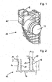
- Fig. 1 shows a generally designated 10 left collection box of the charge air cooler according to the invention according to a preferred embodiment (the indication on the left refers to the direction of travel of the motor vehicle, in which such a heat exchanger is used).
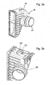
- the Fig. 3a shows the right total collection tank designated 20 of the same heat exchanger. Between the left header 10 and the right header 20 extends a plurality of cooling tubes, which are not shown here.
- thermodynamically highly stressed intercooler which is designed for changing Innehdrücke up to 3.05 bar and fluctuating temperatures of the medium flowing through, in the exemplary embodiment charge air, up to 230 ° C.
- the left collection box 10 ( Fig. 1 ) has a connecting piece 11 through which the charge air to be cooled is introduced, depending on the direction of flow, or the already cooled charge air is discharged.
- the collecting box 10 is formed in one piece from a plastic material and has various ribs.
- the left collection box 10 has a designated 12 fastening means with which the intercooler can be mounted on its left side immediately below another, second heat exchanger, which in the exemplary embodiment, for example, a coolant / air cooler, for example for an internal combustion engine.
- the fastening device 12 is designed as a clip connection, with a corresponding counterpart being provided in a receiving device 41 arranged on the underside of the coolant radiator located above, for fastening purposes.
- a connecting device 42 is formed, which is partially received in the mounting device 41 during assembly.
- a connection contact surface 43 is arranged on the rear side of the connecting device 42, which abuts in the mounted state on a receiving contact surface 44, which is formed in the receiving device 41.
- Fig. 2 shows a section through the fastening device 12 on the left collection box 10.
- the fastening device 12 has in cross section a base 13 on which a first tab 14 and a second tab 16 are each arranged substantially at right angles.
- the tabs 14 and 16 are resiliently formed around its connection point to the base 13 and have at their free, ie resilient ends, in each case a latching lug 15 and 17, respectively.
- the two resilient tabs 14 and 16 are spaced with a Space arranged to each other and extend substantially parallel to the surface.
- the locking lugs 15 and 17 are remote from each other.
- two support ribs 18 and 19 are arranged, which are also spaced from each other and to each other and to the tabs 14 and 16 are substantially parallel to the surface.
- the support ribs 18 and 19 have, starting from the base 13, substantially equal lengths to the tabs 14 and 16.
- the support ribs 18 and 19 serve on the one hand for guidance and on the other hand for connection and balance of forces. In addition, they enhance the resilience of the tabs 14 and 16 both during assembly and when assembled.
- Both the tabs 14 and 16 and the two support ribs 18 and 19 have in the embodiment shown a material thickness of about 2.5 mm.
- the locking shoulder of the locking lug is approximately 3 mm.
- the dimensions given lead to a stable fastening device 12, which is the above-mentioned stresses, in particular forces from the internal pressure change pulses and thermal fluctuations, weight and acceleration forces, and vibration justice.
- the fastening device 12 as well as all associated therewith and previously described items are integrally or integrally formed with the left collection box 10.
- the tabs 14 and 16, as in Fig. 2 shown also be slightly bent or bent.
- the right collection box 20 ( Fig. 3a ) in turn has a connection piece 21.
- a fastening device in the form of a groove 22.
- the groove 22 is open to the right outside of the collecting tank 20 toward V-shaped. The opening angle is approximately 40 °.
- the groove 22 has a width of about 12 mm and a length of about 30 mm.
- FIG. 3b shows a sectional view through the mandrel 19 of the second heat exchanger in the form of a coolant radiator.
- the mandrel 31 is shown in the position in which it is in the assembled state of the intercooler 1, the right collection box 20 is shown.
- the mandrel 31 is connected to a arranged thereon rib on the coolant radiator. When inserted, it is guided transversely to the longitudinal extent of the intercooler with close tolerance, the rib is tapered in this transverse direction. In the longitudinal direction of the charge air cooler, the rib is guided with the mandrel 31 largely displaceable in the longitudinal direction in the groove 22, whereby a length compensation with changing longitudinal extent of the charge air cooler in this direction is possible.
- Fig. 3b is also an embodiment of the spring 32 is shown, which is arranged in this embodiment, the collecting box.
- the rib of the dome 31 is recessed in the region of the spring 32 and engages in the assembled state of the two heat exchangers in the spring.
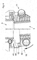
- the Fig. 4 shows the attachment process of the intercooler previously described here in a shortened view with a total of 1 is designated immediately below a designated 3 coolant radiator. Shown is the attachment process on the left side.
- the fastening device formed as a groove of the right header tank 20 of the intercooler is already hooked into a mandrel 31, which is formed at the bottom of the right header box of the coolant radiator 3.
- the fastening device 12 is locked on the left header box 10 of the charge air cooler 1 in the receiving device 41 on the underside of the left header box 10 of the coolant / air cooler 3 (symbolized by the movement arrow in FIG Fig. 4 ).
- the connecting contact surface 43 formed on the rear side of the connecting device 42 contacts the receiving contact surface 44, which is formed in the receiving device 41, and thus serves to guide the assembly movement.
- the two resilient tabs 14 and 16 of the fastening device 12 engage in the corresponding receptacle, whereby a positive connection or attachment takes place.
- the intercooler 1 arranged hanging below the coolant radiator 3, wherein it is fixed on its left side, that is attached without degree of freedom and is movably mounted on its right side by the groove-mandrel guide. Any length, height and / or width changes of the charge air cooler can be achieved by such. Compensate Los fixed storage ideal, while a load-bearing fastening of the intercooler 1 is given at the same time.
- the distance a (see. Fig. 5a ) of both heat exchangers is less than 10 mm.
- the latchable fastening device on the underside of the coolant radiator 3 above (or another second heat exchanger) and on the left header box 10 of the intercooler Provide corresponding receptacle for this purpose.
- the groove 22 and the mandrel 31 can be reversed on the right side. The same applies to a regrouping of all or even individual fastening components between the left and the right side.
Landscapes
- Engineering & Computer Science (AREA)
- Physics & Mathematics (AREA)
- Thermal Sciences (AREA)
- Mechanical Engineering (AREA)
- General Engineering & Computer Science (AREA)
- Heat-Exchange Devices With Radiators And Conduit Assemblies (AREA)
Claims (9)
- Echangeur de chaleur, en particulier refroidisseur d'air de suralimentation (1), comprenant deux bacs collecteurs (10, 20) et une multiplicité de tubes s'étendant entre les bacs collecteurs, ainsi qu'au moins un dispositif de fixation encliquetable (12) servant à la fixation au-dessous d'un deuxième échangeur de chaleur, où le dispositif de fixation encliquetable (12) est disposé sur un bac collecteur (10, 20), caractérisé en ce que l'autre bac collecteur (20, 10) présente un autre dispositif de fixation qui comprend une encoche (22), et en ce que l'autre dispositif de fixation présente une encoche (22) qui présente une dimension longitudinale telle, qu'un dispositif de fixation peut y être logé en étant mobile longitudinalement, et en ce que le dispositif de fixation (12) présente plusieurs pattes élastiques qui sont disposées en étant espacées les unes des autres de façon pratiquement parallèle, et le dispositif de fixation encliquetable (12) présente deux pattes élastiques (14, 16) au niveau des extrémités élastiques desquelles est configuré à chaque fois un ergot d'encliquetage (15, 17), et dans un espace intermédiaire formé entre les deux pattes espacées (14, 16) sont disposées deux nervures de support (18, 19) qui sont configurées en étant pratiquement parallèles à la surface des pattes (14, 16).
- Echangeur de chaleur selon l'une des revendications précédentes, caractérisé en ce qu'au moins un bac collecteur (10, 20) est fabriqué à partir d'une matière plastique, et le dispositif de fixation (12) est conçu en étant intégré à ce bac collecteur (10, 20).
- Echangeur de chaleur selon l'une ou l'autre des revendications précédentes, caractérisé en ce que le dispositif de fixation (12), par rapport à une position de montage de l'échangeur de chaleur, est disposé sur le dessus du bac collecteur (10, 20).
- Echangeur de chaleur selon la revendication 1, 2 ou 3, caractérisé en ce que les pattes élastiques (14, 16) et / ou les nervures de support (18, 19) présentent une épaisseur de paroi de 2 mm à 3 mm, de préférence pratiquement de 2,5 mm, et / ou la longueur élastique des pattes (14, 16) est comprise entre 25 mm et 30 mm.
- Echangeur de chaleur selon l'une quelconque des revendications précédentes, caractérisé en ce qu'un dispositif d'assemblage (42) est disposé au-dessous du dispositif de fixation (12), lequel dispositif d'assemblage présente une surface de contact (43).
- Echangeur de chaleur selon l'une quelconque des revendications précédentes, caractérisé en ce que la distance comprise entre les deux bacs collecteurs (10, 20) est supérieure à 550 mm.
- Système d'échangeurs de chaleur comprenant un premier échangeur de chaleur (1) selon l'une quelconque des revendications précédentes, et au moins un deuxième échangeur de chaleur (3), en particulier un radiateur d'eau, où le premier échangeur de chaleur (1) est disposé au-dessous du deuxième échangeur de chaleur (2) et fixé sur celui-ci.
- Système d'échangeurs de chaleur selon la revendication 7, caractérisé en ce qu'une saillie (31) guidée en étant mobile longitudinalement dans une encoche (22) permet une compensation de tolérance entre les deux échangeurs de chaleur (1, 3).
- Système d'échangeurs de chaleur selon la revendication 7 ou 8, caractérisé en ce qu'une languette (31) est disposée entre les deux échangeurs de chaleur (1, 3), laquelle languette absorbe au moins partiellement des forces s'exerçant entre les deux échangeurs de chaleur (1, 3).
Priority Applications (1)
| Application Number | Priority Date | Filing Date | Title |
|---|---|---|---|
| EP08007269.7A EP2110632B1 (fr) | 2008-04-14 | 2008-04-14 | Echangeur thermique, en particulier refroidisseur d'air de suralimentation, doté d'un dispositif de fixation par clips |
Applications Claiming Priority (1)
| Application Number | Priority Date | Filing Date | Title |
|---|---|---|---|
| EP08007269.7A EP2110632B1 (fr) | 2008-04-14 | 2008-04-14 | Echangeur thermique, en particulier refroidisseur d'air de suralimentation, doté d'un dispositif de fixation par clips |
Publications (2)
| Publication Number | Publication Date |
|---|---|
| EP2110632A1 EP2110632A1 (fr) | 2009-10-21 |
| EP2110632B1 true EP2110632B1 (fr) | 2015-12-02 |
Family
ID=39739507
Family Applications (1)
| Application Number | Title | Priority Date | Filing Date |
|---|---|---|---|
| EP08007269.7A Active EP2110632B1 (fr) | 2008-04-14 | 2008-04-14 | Echangeur thermique, en particulier refroidisseur d'air de suralimentation, doté d'un dispositif de fixation par clips |
Country Status (1)
| Country | Link |
|---|---|
| EP (1) | EP2110632B1 (fr) |
Families Citing this family (2)
| Publication number | Priority date | Publication date | Assignee | Title |
|---|---|---|---|---|
| DE102011084307B4 (de) * | 2011-10-11 | 2025-04-24 | Mahle International Gmbh | Kühlervorrichtung und Verfahren zur Herstellung einer Kühlervorrichtung für ein Fahrzeug |
| DE102013202146A1 (de) * | 2013-02-08 | 2014-08-14 | Behr Gmbh & Co. Kg | Kühlervorrichtung und Verfahren zur Herstellung einer Kühlervorrichtung |
Family Cites Families (5)
| Publication number | Priority date | Publication date | Assignee | Title |
|---|---|---|---|---|
| DE4425350A1 (de) * | 1994-07-18 | 1996-01-25 | Behr Gmbh & Co | Anordnung zur Verbindung von zwei oder mehr Wärmetauschern |
| DE29712351U1 (de) * | 1997-07-12 | 1997-09-11 | Behr GmbH & Co., 70469 Stuttgart | Wärmeübertrageranordnung mit zwei Wärmeübertragern |
| DE19953787B4 (de) * | 1999-11-09 | 2005-12-15 | Behr Gmbh & Co. Kg | Anordnung zur Verbindung von zwei Wärmeübertragern |
| DE102005004521A1 (de) * | 2004-01-29 | 2005-08-18 | Behr Gmbh & Co. Kg | Anordnung zur gegenseitigen Befestigung von Wärmeübertragern |
| FR2871108B1 (fr) | 2004-06-04 | 2007-11-02 | Peugeot Citroen Automobiles Sa | Dispositif de montage d'une facade avant d'un vehicule automobile equipee notamment d'un refroidisseur d'air de suralimentation |
-
2008
- 2008-04-14 EP EP08007269.7A patent/EP2110632B1/fr active Active
Also Published As
| Publication number | Publication date |
|---|---|
| EP2110632A1 (fr) | 2009-10-21 |
Similar Documents
| Publication | Publication Date | Title |
|---|---|---|
| EP1830048B1 (fr) | Echangeur thermique doté d'une plaque de raccordement, en particulier refroidisseur de l'air de suralimentation | |
| EP3313679B1 (fr) | Installation de climatisation pour véhicule, en particulier installation de climatisation sur toit et véhicule équipé d'une telle installation de climatisation | |
| EP1714098B1 (fr) | Agencement de deux échangeurs thermiques | |
| DE102011084307B4 (de) | Kühlervorrichtung und Verfahren zur Herstellung einer Kühlervorrichtung für ein Fahrzeug | |
| EP1478539A1 (fr) | Support de montage de la partie avant d'un vehicule automobile et procede pour fixer de fa on amovible un module de refroidissement a un support de montage d'une partie avant de vehicule | |
| EP2161529B1 (fr) | Elément de support destiné au support élastique d'au moins un caloporteur dans un véhicule automobile et caloporteur pour un véhicule automobile | |
| EP1489375A1 (fr) | Unité d'échangeur de chaleur | |
| EP3488498A1 (fr) | Ensemble formant cadre de support muni d'un cadre de base et d'un élément de fixation et procédé d'assemblage | |
| DE102007007607A1 (de) | Schutzvorrichtung für einen Wärmetauscher eines Kraftfahrzeugs | |
| DE102016205853A1 (de) | Anordnung einer Frischluftklappe in einem Vorderwagen eines Kraftfahrzeuges | |
| EP2110632A1 (fr) | Echangeur thermique, en particulier refroidisseur d'air de suralimentation, doté d'un dispositif de fixation par clips | |
| DE202013102202U1 (de) | Kompaktlager mit mehrteiligem Rahmen aus Strangprofilabschnitten | |
| EP1757888B1 (fr) | Agencement de deux échangeurs de chaleur | |
| EP2418451B1 (fr) | Agencement comprenant un échangeur de chaleur, un autre composant et un support de module | |
| EP1890102B1 (fr) | Plaque tubulaire voûtée pour un bac collecteur d'un échangeur thermique | |
| DE102007006241A1 (de) | Befestigungsanordnung für Wärmeübertrager | |
| DE102013202146A1 (de) | Kühlervorrichtung und Verfahren zur Herstellung einer Kühlervorrichtung | |
| DE102018124895A1 (de) | Modulares, motorisiertes Antriebssystem, Modul, Verwendung und Fertigungsverfahren dafür | |
| DE102008045341A1 (de) | Aggregatlager | |
| DE202009011439U1 (de) | Anordnung zur Befestigung eines ersten Wärmeübertragers an einem zweiten Wärmeübertrager | |
| DE10343634A1 (de) | Wärmeaustauscher für Kraftfahrzeuge | |
| DE102008035020A1 (de) | Wärmeübertrager | |
| DE19930689B4 (de) | Wärmeübertrager mit Halter | |
| EP2392883B1 (fr) | Refroidisseur d'agent refroidissant | |
| DE102012020397A1 (de) | Anordnung eines Behälters an einer Haltestruktur sowie Verfahren zu deren Montage |
Legal Events
| Date | Code | Title | Description |
|---|---|---|---|
| PUAI | Public reference made under article 153(3) epc to a published international application that has entered the european phase |
Free format text: ORIGINAL CODE: 0009012 |
|
| AK | Designated contracting states |
Kind code of ref document: A1 Designated state(s): AT BE BG CH CY CZ DE DK EE ES FI FR GB GR HR HU IE IS IT LI LT LU LV MC MT NL NO PL PT RO SE SI SK TR |
|
| AX | Request for extension of the european patent |
Extension state: AL BA MK RS |
|
| 17P | Request for examination filed |
Effective date: 20100421 |
|
| AKX | Designation fees paid |
Designated state(s): CZ DE ES FR GB |
|
| 17Q | First examination report despatched |
Effective date: 20100609 |
|
| GRAP | Despatch of communication of intention to grant a patent |
Free format text: ORIGINAL CODE: EPIDOSNIGR1 |
|
| INTG | Intention to grant announced |
Effective date: 20150626 |
|
| RAP1 | Party data changed (applicant data changed or rights of an application transferred) |
Owner name: MAHLE BEHR SPAIN S.A. |
|
| GRAS | Grant fee paid |
Free format text: ORIGINAL CODE: EPIDOSNIGR3 |
|
| GRAA | (expected) grant |
Free format text: ORIGINAL CODE: 0009210 |
|
| AK | Designated contracting states |
Kind code of ref document: B1 Designated state(s): CZ DE ES FR GB |
|
| REG | Reference to a national code |
Ref country code: GB Ref legal event code: FG4D Free format text: NOT ENGLISH |
|
| REG | Reference to a national code |
Ref country code: DE Ref legal event code: R096 Ref document number: 502008013620 Country of ref document: DE |
|
| REG | Reference to a national code |
Ref country code: FR Ref legal event code: PLFP Year of fee payment: 9 |
|
| PG25 | Lapsed in a contracting state [announced via postgrant information from national office to epo] |
Ref country code: ES Free format text: LAPSE BECAUSE OF FAILURE TO SUBMIT A TRANSLATION OF THE DESCRIPTION OR TO PAY THE FEE WITHIN THE PRESCRIBED TIME-LIMIT Effective date: 20151202 |
|
| PG25 | Lapsed in a contracting state [announced via postgrant information from national office to epo] |
Ref country code: CZ Free format text: LAPSE BECAUSE OF FAILURE TO SUBMIT A TRANSLATION OF THE DESCRIPTION OR TO PAY THE FEE WITHIN THE PRESCRIBED TIME-LIMIT Effective date: 20151202 |
|
| REG | Reference to a national code |
Ref country code: DE Ref legal event code: R097 Ref document number: 502008013620 Country of ref document: DE |
|
| PLBE | No opposition filed within time limit |
Free format text: ORIGINAL CODE: 0009261 |
|
| STAA | Information on the status of an ep patent application or granted ep patent |
Free format text: STATUS: NO OPPOSITION FILED WITHIN TIME LIMIT |
|
| 26N | No opposition filed |
Effective date: 20160905 |
|
| GBPC | Gb: european patent ceased through non-payment of renewal fee |
Effective date: 20160414 |
|
| PG25 | Lapsed in a contracting state [announced via postgrant information from national office to epo] |
Ref country code: GB Free format text: LAPSE BECAUSE OF NON-PAYMENT OF DUE FEES Effective date: 20160414 |
|
| REG | Reference to a national code |
Ref country code: FR Ref legal event code: PLFP Year of fee payment: 10 |
|
| REG | Reference to a national code |
Ref country code: FR Ref legal event code: PLFP Year of fee payment: 11 |
|
| PGFP | Annual fee paid to national office [announced via postgrant information from national office to epo] |
Ref country code: FR Payment date: 20230424 Year of fee payment: 16 |
|
| PG25 | Lapsed in a contracting state [announced via postgrant information from national office to epo] |
Ref country code: FR Free format text: LAPSE BECAUSE OF NON-PAYMENT OF DUE FEES Effective date: 20240430 |
|
| PG25 | Lapsed in a contracting state [announced via postgrant information from national office to epo] |
Ref country code: FR Free format text: LAPSE BECAUSE OF NON-PAYMENT OF DUE FEES Effective date: 20240430 |
|
| PGFP | Annual fee paid to national office [announced via postgrant information from national office to epo] |
Ref country code: DE Payment date: 20250422 Year of fee payment: 18 |