EP2110660B1 - Sensorvorrichtung, System und Verfahren zur Kontrolle eines anaeroben Verdauungsprozesses - Google Patents
Sensorvorrichtung, System und Verfahren zur Kontrolle eines anaeroben Verdauungsprozesses Download PDFInfo
- Publication number
- EP2110660B1 EP2110660B1 EP08154460A EP08154460A EP2110660B1 EP 2110660 B1 EP2110660 B1 EP 2110660B1 EP 08154460 A EP08154460 A EP 08154460A EP 08154460 A EP08154460 A EP 08154460A EP 2110660 B1 EP2110660 B1 EP 2110660B1
- Authority
- EP
- European Patent Office
- Prior art keywords
- electrodes
- sensor device
- end surface
- electrode
- operative end
- Prior art date
- Legal status (The legal status is an assumption and is not a legal conclusion. Google has not performed a legal analysis and makes no representation as to the accuracy of the status listed.)
- Not-in-force
Links
- 238000000034 method Methods 0.000 title claims abstract description 125
- 230000008569 process Effects 0.000 title claims abstract description 95
- 230000029087 digestion Effects 0.000 title claims abstract description 50
- 238000012544 monitoring process Methods 0.000 title claims abstract description 24
- 239000007788 liquid Substances 0.000 claims abstract description 63
- 239000000523 sample Substances 0.000 claims abstract description 63
- 230000004044 response Effects 0.000 claims abstract description 54
- 239000011368 organic material Substances 0.000 claims abstract description 37
- 239000000356 contaminant Substances 0.000 claims abstract description 25
- 238000000491 multivariate analysis Methods 0.000 claims description 16
- 239000010935 stainless steel Substances 0.000 claims description 11
- 229910001220 stainless steel Inorganic materials 0.000 claims description 11
- 229910052751 metal Inorganic materials 0.000 claims description 7
- 239000002184 metal Substances 0.000 claims description 7
- 239000010931 gold Substances 0.000 claims description 6
- 238000012545 processing Methods 0.000 claims description 6
- 238000000227 grinding Methods 0.000 claims description 5
- GKOZUEZYRPOHIO-UHFFFAOYSA-N iridium atom Chemical compound [Ir] GKOZUEZYRPOHIO-UHFFFAOYSA-N 0.000 claims description 5
- 239000004575 stone Substances 0.000 claims description 5
- 229910052737 gold Inorganic materials 0.000 claims description 4
- 238000005299 abrasion Methods 0.000 claims description 3
- 239000012777 electrically insulating material Substances 0.000 claims description 3
- PCHJSUWPFVWCPO-UHFFFAOYSA-N gold Chemical compound [Au] PCHJSUWPFVWCPO-UHFFFAOYSA-N 0.000 claims description 3
- 239000011159 matrix material Substances 0.000 claims description 3
- 229910000575 Ir alloy Inorganic materials 0.000 claims 2
- 229910001260 Pt alloy Inorganic materials 0.000 claims 2
- 238000005259 measurement Methods 0.000 description 52
- 239000007789 gas Substances 0.000 description 37
- 230000035611 feeding Effects 0.000 description 33
- 238000002474 experimental method Methods 0.000 description 30
- 239000000758 substrate Substances 0.000 description 29
- BASFCYQUMIYNBI-UHFFFAOYSA-N platinum Chemical compound [Pt] BASFCYQUMIYNBI-UHFFFAOYSA-N 0.000 description 21
- 239000010802 sludge Substances 0.000 description 14
- 230000000694 effects Effects 0.000 description 13
- 239000000047 product Substances 0.000 description 12
- 229910052697 platinum Inorganic materials 0.000 description 11
- 238000004519 manufacturing process Methods 0.000 description 10
- 238000000083 pulse voltammetry Methods 0.000 description 10
- CURLTUGMZLYLDI-UHFFFAOYSA-N Carbon dioxide Chemical compound O=C=O CURLTUGMZLYLDI-UHFFFAOYSA-N 0.000 description 9
- 230000006870 function Effects 0.000 description 9
- 239000002002 slurry Substances 0.000 description 8
- 238000003756 stirring Methods 0.000 description 8
- 241000196324 Embryophyta Species 0.000 description 7
- 229910052741 iridium Inorganic materials 0.000 description 7
- 239000000463 material Substances 0.000 description 7
- VNWKTOKETHGBQD-UHFFFAOYSA-N methane Chemical compound C VNWKTOKETHGBQD-UHFFFAOYSA-N 0.000 description 7
- 238000000513 principal component analysis Methods 0.000 description 7
- 239000007787 solid Substances 0.000 description 7
- 238000004458 analytical method Methods 0.000 description 6
- 239000001569 carbon dioxide Substances 0.000 description 6
- 229910002092 carbon dioxide Inorganic materials 0.000 description 6
- 238000004140 cleaning Methods 0.000 description 6
- FERIUCNNQQJTOY-UHFFFAOYSA-N Butyric acid Natural products CCCC(O)=O FERIUCNNQQJTOY-UHFFFAOYSA-N 0.000 description 5
- 230000008901 benefit Effects 0.000 description 5
- 238000013461 design Methods 0.000 description 5
- 230000014759 maintenance of location Effects 0.000 description 5
- 244000005700 microbiome Species 0.000 description 5
- 235000015097 nutrients Nutrition 0.000 description 5
- 239000012071 phase Substances 0.000 description 5
- 239000010948 rhodium Substances 0.000 description 5
- 239000000126 substance Substances 0.000 description 5
- XLYOFNOQVPJJNP-UHFFFAOYSA-N water Chemical compound O XLYOFNOQVPJJNP-UHFFFAOYSA-N 0.000 description 5
- 229910045601 alloy Inorganic materials 0.000 description 4
- 239000000956 alloy Substances 0.000 description 4
- XBDQKXXYIPTUBI-UHFFFAOYSA-N dimethylselenoniopropionate Natural products CCC(O)=O XBDQKXXYIPTUBI-UHFFFAOYSA-N 0.000 description 4
- 238000005516 engineering process Methods 0.000 description 4
- 230000007613 environmental effect Effects 0.000 description 4
- 238000000855 fermentation Methods 0.000 description 4
- 230000004151 fermentation Effects 0.000 description 4
- 238000012417 linear regression Methods 0.000 description 4
- 239000007791 liquid phase Substances 0.000 description 4
- 230000000813 microbial effect Effects 0.000 description 4
- 239000004033 plastic Substances 0.000 description 4
- 229910052703 rhodium Inorganic materials 0.000 description 4
- 239000010822 slaughterhouse waste Substances 0.000 description 4
- 241000894006 Bacteria Species 0.000 description 3
- 239000002253 acid Substances 0.000 description 3
- 230000009471 action Effects 0.000 description 3
- 238000013528 artificial neural network Methods 0.000 description 3
- 239000007795 chemical reaction product Substances 0.000 description 3
- 230000000295 complement effect Effects 0.000 description 3
- 239000012153 distilled water Substances 0.000 description 3
- 229920001971 elastomer Polymers 0.000 description 3
- 239000001257 hydrogen Substances 0.000 description 3
- 229910052739 hydrogen Inorganic materials 0.000 description 3
- 230000002503 metabolic effect Effects 0.000 description 3
- 238000002156 mixing Methods 0.000 description 3
- 239000000203 mixture Substances 0.000 description 3
- 230000020477 pH reduction Effects 0.000 description 3
- 230000036961 partial effect Effects 0.000 description 3
- 230000002829 reductive effect Effects 0.000 description 3
- LFQSCWFLJHTTHZ-UHFFFAOYSA-N Ethanol Chemical compound CCO LFQSCWFLJHTTHZ-UHFFFAOYSA-N 0.000 description 2
- UFHFLCQGNIYNRP-UHFFFAOYSA-N Hydrogen Chemical compound [H][H] UFHFLCQGNIYNRP-UHFFFAOYSA-N 0.000 description 2
- 230000005856 abnormality Effects 0.000 description 2
- 238000009825 accumulation Methods 0.000 description 2
- QVGXLLKOCUKJST-UHFFFAOYSA-N atomic oxygen Chemical compound [O] QVGXLLKOCUKJST-UHFFFAOYSA-N 0.000 description 2
- 230000008859 change Effects 0.000 description 2
- 238000004587 chromatography analysis Methods 0.000 description 2
- 230000003247 decreasing effect Effects 0.000 description 2
- 230000001419 dependent effect Effects 0.000 description 2
- 235000014113 dietary fatty acids Nutrition 0.000 description 2
- 239000007772 electrode material Substances 0.000 description 2
- 229930195729 fatty acid Natural products 0.000 description 2
- 239000000194 fatty acid Substances 0.000 description 2
- 150000004665 fatty acids Chemical class 0.000 description 2
- 239000011521 glass Substances 0.000 description 2
- 238000000691 measurement method Methods 0.000 description 2
- 239000005416 organic matter Substances 0.000 description 2
- 239000001301 oxygen Substances 0.000 description 2
- 229910052760 oxygen Inorganic materials 0.000 description 2
- 238000012628 principal component regression Methods 0.000 description 2
- 238000003672 processing method Methods 0.000 description 2
- 235000019260 propionic acid Nutrition 0.000 description 2
- IUVKMZGDUIUOCP-BTNSXGMBSA-N quinbolone Chemical compound O([C@H]1CC[C@H]2[C@H]3[C@@H]([C@]4(C=CC(=O)C=C4CC3)C)CC[C@@]21C)C1=CCCC1 IUVKMZGDUIUOCP-BTNSXGMBSA-N 0.000 description 2
- 230000009467 reduction Effects 0.000 description 2
- MHOVAHRLVXNVSD-UHFFFAOYSA-N rhodium atom Chemical compound [Rh] MHOVAHRLVXNVSD-UHFFFAOYSA-N 0.000 description 2
- 238000005070 sampling Methods 0.000 description 2
- 238000007789 sealing Methods 0.000 description 2
- 238000004832 voltammetry Methods 0.000 description 2
- 239000002699 waste material Substances 0.000 description 2
- 238000004065 wastewater treatment Methods 0.000 description 2
- QTBSBXVTEAMEQO-UHFFFAOYSA-M Acetate Chemical compound CC([O-])=O QTBSBXVTEAMEQO-UHFFFAOYSA-M 0.000 description 1
- 235000016068 Berberis vulgaris Nutrition 0.000 description 1
- 241000335053 Beta vulgaris Species 0.000 description 1
- 241000219310 Beta vulgaris subsp. vulgaris Species 0.000 description 1
- BVKZGUZCCUSVTD-UHFFFAOYSA-M Bicarbonate Chemical compound OC([O-])=O BVKZGUZCCUSVTD-UHFFFAOYSA-M 0.000 description 1
- FERIUCNNQQJTOY-UHFFFAOYSA-M Butyrate Chemical compound CCCC([O-])=O FERIUCNNQQJTOY-UHFFFAOYSA-M 0.000 description 1
- 229920002449 FKM Polymers 0.000 description 1
- 241000208818 Helianthus Species 0.000 description 1
- 235000003222 Helianthus annuus Nutrition 0.000 description 1
- XBDQKXXYIPTUBI-UHFFFAOYSA-M Propionate Chemical compound CCC([O-])=O XBDQKXXYIPTUBI-UHFFFAOYSA-M 0.000 description 1
- 229910021607 Silver chloride Inorganic materials 0.000 description 1
- 238000003070 Statistical process control Methods 0.000 description 1
- 235000021536 Sugar beet Nutrition 0.000 description 1
- 240000008042 Zea mays Species 0.000 description 1
- 235000016383 Zea mays subsp huehuetenangensis Nutrition 0.000 description 1
- 235000002017 Zea mays subsp mays Nutrition 0.000 description 1
- 230000000789 acetogenic effect Effects 0.000 description 1
- 150000007513 acids Chemical class 0.000 description 1
- 230000002411 adverse Effects 0.000 description 1
- 150000001298 alcohols Chemical class 0.000 description 1
- XKMRRTOUMJRJIA-UHFFFAOYSA-N ammonia nh3 Chemical compound N.N XKMRRTOUMJRJIA-UHFFFAOYSA-N 0.000 description 1
- 239000012491 analyte Substances 0.000 description 1
- 238000013459 approach Methods 0.000 description 1
- 239000007864 aqueous solution Substances 0.000 description 1
- 230000009286 beneficial effect Effects 0.000 description 1
- 230000031018 biological processes and functions Effects 0.000 description 1
- 229960000074 biopharmaceutical Drugs 0.000 description 1
- 229920001222 biopolymer Polymers 0.000 description 1
- 230000015572 biosynthetic process Effects 0.000 description 1
- 235000000332 black box Nutrition 0.000 description 1
- 239000000969 carrier Substances 0.000 description 1
- 235000013339 cereals Nutrition 0.000 description 1
- 238000004737 colorimetric analysis Methods 0.000 description 1
- 239000000470 constituent Substances 0.000 description 1
- 238000010924 continuous production Methods 0.000 description 1
- 238000011217 control strategy Methods 0.000 description 1
- 238000006731 degradation reaction Methods 0.000 description 1
- 238000010790 dilution Methods 0.000 description 1
- 239000012895 dilution Substances 0.000 description 1
- 230000005611 electricity Effects 0.000 description 1
- 239000003822 epoxy resin Substances 0.000 description 1
- 230000002349 favourable effect Effects 0.000 description 1
- 210000003608 fece Anatomy 0.000 description 1
- 239000003337 fertilizer Substances 0.000 description 1
- 235000013305 food Nutrition 0.000 description 1
- 239000000446 fuel Substances 0.000 description 1
- 238000004817 gas chromatography Methods 0.000 description 1
- 238000010438 heat treatment Methods 0.000 description 1
- 150000002431 hydrogen Chemical class 0.000 description 1
- 230000003301 hydrolyzing effect Effects 0.000 description 1
- 238000007654 immersion Methods 0.000 description 1
- 230000005764 inhibitory process Effects 0.000 description 1
- 238000003780 insertion Methods 0.000 description 1
- 230000037431 insertion Effects 0.000 description 1
- 150000002500 ions Chemical class 0.000 description 1
- KQNPFQTWMSNSAP-UHFFFAOYSA-N isobutyric acid Chemical compound CC(C)C(O)=O KQNPFQTWMSNSAP-UHFFFAOYSA-N 0.000 description 1
- 230000002045 lasting effect Effects 0.000 description 1
- 238000004811 liquid chromatography Methods 0.000 description 1
- 239000010871 livestock manure Substances 0.000 description 1
- 235000009973 maize Nutrition 0.000 description 1
- 230000007246 mechanism Effects 0.000 description 1
- 239000002207 metabolite Substances 0.000 description 1
- 150000002739 metals Chemical class 0.000 description 1
- 230000000696 methanogenic effect Effects 0.000 description 1
- 235000013336 milk Nutrition 0.000 description 1
- 239000008267 milk Substances 0.000 description 1
- 210000004080 milk Anatomy 0.000 description 1
- 239000003345 natural gas Substances 0.000 description 1
- 229910052759 nickel Inorganic materials 0.000 description 1
- 239000010815 organic waste Substances 0.000 description 1
- 230000010355 oscillation Effects 0.000 description 1
- 239000002245 particle Substances 0.000 description 1
- 230000000737 periodic effect Effects 0.000 description 1
- 239000007793 ph indicator Substances 0.000 description 1
- 229920000647 polyepoxide Polymers 0.000 description 1
- 244000144977 poultry Species 0.000 description 1
- 238000002360 preparation method Methods 0.000 description 1
- 238000004886 process control Methods 0.000 description 1
- 230000002035 prolonged effect Effects 0.000 description 1
- 238000005086 pumping Methods 0.000 description 1
- 238000011084 recovery Methods 0.000 description 1
- 229910052702 rhenium Inorganic materials 0.000 description 1
- 229910052707 ruthenium Inorganic materials 0.000 description 1
- 230000035945 sensitivity Effects 0.000 description 1
- HBMJWWWQQXIZIP-UHFFFAOYSA-N silicon carbide Chemical compound [Si+]#[C-] HBMJWWWQQXIZIP-UHFFFAOYSA-N 0.000 description 1
- 229910010271 silicon carbide Inorganic materials 0.000 description 1
- HKZLPVFGJNLROG-UHFFFAOYSA-M silver monochloride Chemical compound [Cl-].[Ag+] HKZLPVFGJNLROG-UHFFFAOYSA-M 0.000 description 1
- 238000003307 slaughter Methods 0.000 description 1
- 239000002904 solvent Substances 0.000 description 1
- 238000002798 spectrophotometry method Methods 0.000 description 1
- 239000007921 spray Substances 0.000 description 1
- 230000003068 static effect Effects 0.000 description 1
- 238000006467 substitution reaction Methods 0.000 description 1
- 238000012360 testing method Methods 0.000 description 1
- 229910052719 titanium Inorganic materials 0.000 description 1
- 238000004448 titration Methods 0.000 description 1
- 231100000167 toxic agent Toxicity 0.000 description 1
- 239000002351 wastewater Substances 0.000 description 1
- 239000002023 wood Substances 0.000 description 1
Images







Classifications
-
- G—PHYSICS
- G01—MEASURING; TESTING
- G01N—INVESTIGATING OR ANALYSING MATERIALS BY DETERMINING THEIR CHEMICAL OR PHYSICAL PROPERTIES
- G01N27/00—Investigating or analysing materials by the use of electric, electrochemical, or magnetic means
- G01N27/26—Investigating or analysing materials by the use of electric, electrochemical, or magnetic means by investigating electrochemical variables; by using electrolysis or electrophoresis
- G01N27/28—Electrolytic cell components
- G01N27/30—Electrodes, e.g. test electrodes; Half-cells
- G01N27/38—Cleaning of electrodes
Definitions
- the present invention relates to a sensor device for monitoring an anaerobic digestion process in an electrically conductive liquid comprising organic material, which sensor device comprises an electrochemical probe and is based on pulse voltammetry.
- the present invention relates to a system for monitoring an anaerobic digestion process in an electrically conductive liquid comprising organic material, which system comprises the sensor device according to the invention.
- the present invention relates to a method for monitoring an anaerobic digestion process in an electrically conductive liquid comprising organic material.
- Anaerobic digestion processes are processes in which microorganisms such as, for example, bacteria, break down (i.e. , digest) a substrate in the form of organic material. The digestion is performed in the absence of oxygen and results in a product and digested sludge.
- anaerobic digestion processes of organic material may be utilized in order to produce energy carriers or reduce volumes of waste.
- anaerobic digestion processes for such aims have received a lot of attention because of the multiple environmental benefits and resource efficiency associated therewith.
- biogas One example of a product that may be produced by means of an anaerobic digestion process of organic material is biogas.
- the produced biogas may be used for, for example, heating, electricity generation, as vehicle fuel, or it may be distributed via a natural-gas grid.
- the implementation of biogas systems often leads to significant improvements concerning resource efficiency and environmental impacts compared to traditional waste handling (Börjesson and Berglund, 2007).
- Another interesting product of anaerobic digestion processes is hydrogen because of its very high calorific value. Indirect energy or environmental impacts may also be of great importance, e.g. , the (partial) replacement of chemical fertilizers by the digested substrate.
- organic materials may be used as substrates in anaerobic digestion processes, e.g. , farm products (liquid manure, poultry excrements, grain, maize, green rye, rape, sunflowers, fodder beets, sugar beets, etc.) or organic waste (from breweries, food markets, distilleries, slaughter houses, waste water treatment plants, etc.).
- farm products liquid manure, poultry excrements, grain, maize, green rye, rape, sunflowers, fodder beets, sugar beets, etc.
- organic waste from breweries, food markets, distilleries, slaughter houses, waste water treatment plants, etc.
- the organic material is usually processed under dry conditions (> 25% total solids), semi-dry conditions (16 - 22% total solids) or wet conditions (3 - 8% total solids).
- Anaerobic digestion plants are usually designed for continuous operation in a one-stage process where organic matter is digested in a closed reactor to produce, e.g. , biogas and at the same time reduce the amount of organic material. Variations of process types are in use today where, e.g. , two-stage and two-phase digestion processes utilize two reactors with different retention times. In addition, there are many different types of reactors known today for utilization in anaerobic digestion processes, e.g. , anaerobic filter beds, continuously stirred tank reactors and plug-flow reactors.
- a typical plant incorporates a mixing tank for blending ground organic matter with a liquid in order to form a substrate slurry, a feeding device for feeding the slurry into the reactor, and a reservoir for the digested substrate.
- VFAs volatile fatty acids
- H 2 hydrogen
- CO 2 carbon dioxide
- the methanogens are the slowest growing and the most sensitive organisms of those mentioned and adverse process conditions such as organic overload, unfavorable pH, or the presence of toxic compounds, may affect the methanogens negatively, which in turn may lead to process instability. This may be observed by elevated concentrations of metabolites, such as H 2 , VFAs, and alcohols, in the metabolic chain preceding the action of the methanogens. For instance, increased levels of VFAs may cause a decrease of the pH, which in severe cases may lead to acidification of the reactor with complete inhibition of the methanogenic activity. This situation makes it necessary to remove the reactor content and to restart the process.
- the feed rate in anaerobic digestion processes i.e. , the amount and frequency of adding new substrate to the reactor, is usually adjusted depending on the current (microbial) status of the reactor and the amount of nutrients present in the used substrate, resulting in a certain hydraulic retention time.
- a shortfall of nutrients results in an immediate reduction of the product quantity while a surplus of nutrients results in an unbalanced state of the reactor that over time results in a reduction of product quantity.
- Longer periods of shortfall of nutrients i.e. , too long retention time of the substrate in the reactor
- surplus of nutrients i.e. , too short retention time of the substrate in the reactor
- a common way of preventing instability problems in anaerobic digestion processes, e.g. , acidification, is to keep the organic load of the reactor far below its maximum capacity.
- a more economically favorable way of operating a plant and avoiding instability problems is to monitor the process in order to detect instability problems.
- countermeasures to compensate for the instability may be implemented. For example, the feed rate may be adjusted in order to counteract instability problems.
- alkalinity and VFA concentrations may serve as efficient indicators of process imbalances. pH is commonly used as a process indicator, but the effectiveness of using this as a control parameter is strongly dependent on the alkalinity of the process (Ahring et al., 1995). On-line methods for monitoring alkalinity have been developed based on sample saturation with carbon dioxide and acidification to release bicarbonate as carbon dioxide with subsequent gas-pressure or gas-flow determination (Hawkes et al. , 1993; Rozzi and DiPinto, 1994).
- the on-line chromatography methods can analyze individual VFAs, but a disadvantage is that one or more sample preparation steps must be included because most of the samples are not fully compatible with the chromatographic analysis. These steps often result in a highly complex instrumentation (Diamantis et al., 2006).
- biogas production plants the use of on-line instrumentation and control equipment is only in its early stage as compared to other biological processes, e.g. , waste water treatment plants or biopharmaceutical processes. Therefore, many biogas production plants run sub-optimally and are operated in critical load ranges for economic reasons (Kujawski et a / . , 2007).
- a sensor system that may be utilized for monitoring a parameter, such as the concentration of an analyte, pH, etc., in a liquid is the voltammetric electronic tongue disclosed in WO 99/13325 and in the article by F. Winquist et al., "Monitoring of freshness of milk by an electronic tongue on the basis of voltammetry", Meas. Sci. Technol, 9 (1998) 1937-1946 . More specifically, WO 99/13325 and the mentioned article disclose a sensor device comprising a probe with at least one working electrode and an auxiliary (counter) electrode. The sensor device comprises further a control unit, e.g. , a potentiostat.
- a control unit e.g. , a potentiostat.
- the working electrode(s) and the auxiliary electrode are connected to the control unit, and each electrode has an operative end surface adapted to be arranged in contact with the liquid in order to form an electric circuit.
- the measurement principle is based on pulse voltammetry, whereby a series of different voltage pulses are applied between the working and auxiliary electrodes by means of the control unit, and the resulting electric current in the electric circuit, including transients, is recorded by means of the control unit at different potentials.
- the recorded electric current is then analyzed using means for performing multivariate signal processing methods in order to obtain information about a parameter in a liquid.
- the means for performing multivariate signal processing methods is connected to the control unit of the sensor device.
- the information content in the measurements may be increased by utilizing multiple working electrodes made from different materials and by varying the number, amplitude and/or timing of the applied voltage pulses.
- the sensor device and system disclosed in WO 99/13325 and the mentioned article by F. Winquist et al. are not suitable to utilize for monitoring an anaerobic digestion process in an electrically conductive reactor liquid comprising organic material.
- gas bubbles produced during the anaerobic digestion process accumulate ( i.e. , they are loosely bound) on the operative end surface of the electrodes.
- other contaminants such as reaction products are loosely or tightly bound to the end surface of the electrodes.
- Contaminants in the form of, for example, sticking gas bubbles and reaction products imply that a response signal corresponding to the resulting electric current in the electric circuit drops (i.e. , the response signal is instable), whereby no relevant measurements may be made by means of the sensor device.
- WO99/57551 discloses a wood chip digester comprising an electrode cleaning mechanism comprising a rotating shaft and a cleaning baffle (9) which directs solvent supplied under pressure to hit the underside of the electrodes (7); the spray action removes built-up material deposits from the electrode surface.
- one object of the present invention is to provide an improved sensor device for monitoring an anaerobic digestion process in an electrically conductive liquid comprising organic material, said sensor device comprising:
- the sensor device further comprises an abrasive device having at least one abrading surface, said abrasive device being movable in a predetermined pattern in relation to said operative end surface of said electrodes and being arranged in relation to said electrodes such that said operative end surface of each electrode is contacted by at least one of said abrading surfaces during movement of said abrasive device in said predetermined pattern so as to abrade contaminants bound thereon, and said abrasive device being mounted on a mounting means via which said abrasive device is connectable to a drive unit for driving the movement of said abrasive device.
- Another object of the present invention is to provide an improved method for monitoring an anaerobic digestion process in an electrically conductive liquid comprising organic material, said method comprising the steps of:
- This object is achieved by the fact that contaminants bound to said operative end surface of said electrodes are abraded, said abrading being performed by means of an abrasive device having at least one abrading surface, said abrasive device being movable in a predetermined pattern in relation to said operative end surface of said electrodes and being arranged in relation to said electrodes such that said operative end surface of each electrode is contacted by at least one of said abrading surfaces during movement of said abrasive device in said predetermined pattern so as to abrade contaminants bound thereon.
- an “electrically conductive liquid comprising organic material” may be formed by adding organic material to an electrically conductive liquid (e.g. , water).
- an "electrically conductive liquid comprising organic material” may be formed by adding organic material to a liquid not being electrically conductive (e.g. , distilled water), whereby an electrically conductive liquid comprising organic material is formed due to the fact that organic material utilized in anaerobic digestion processes partly dissolve upon being added to said liquid, releasing large amounts of ions.
- the organic material may be partly suspended in the electrically conductive liquid.
- Figure 1 a shows schematically a first embodiment of a sensor device 1 according to the invention in a partly cross-sectional view and figure 1 b shows an end view of the first embodiment of the sensor device 1.
- the sensor device 1 according to the invention comprises a probe 2 comprising a working electrode 3 and an auxiliary (counter) electrode 4.
- the probe 2 comprises one working electrode 3.
- the probe 2 comprises more than one working electrode 3.
- Each electrode 3, 4 has an operative end surface 5, which is adapted to be arranged in contact with an electrically conductive liquid comprising organic material.
- the probe 2 may also be denoted as an electrochemical probe.
- the sensor device 1 is designed for utilization of pulse voltammetry for measurements of an electrically conductive liquid comprising organic material, i.e. , the sensor device 1 is based on pulse voltammetry. Therefore, the sensor device 1 comprises further a control unit 6.
- the control unit 6 is arranged to apply a series of voltage pulses between the working electrode 3 and the auxiliary electrode 4, i.e. , it is arranged to apply a varying potential to the working electrode 3 and the auxiliary electrode 4 according to a predetermined pattern. More specifically, the control unit 6 is connected to the electrodes 3, 4 by electrical leads 7, 8, whereby a closed circuit is formed when the operative end surface 5 of the electrodes 3, 4 is in contact with an electrically conductive liquid.
- the electrodes 3, 4 are coupled to the control unit 6 such that a standard two-electrode configuration is achieved.
- An electric current flows through the closed circuit as a response to an applied voltage pulse between the working electrode 3 and the auxiliary electrode 4.
- the control unit 6 is further arranged to record a response signal corresponding to an electric current generated in the electric circuit in response to an applied voltage pulse.
- control unit 6 may comprise a potentiostat which supervises that the predetermined potential at a certain moment is maintained and which records the created current response signal.
- control unit 6 may comprise any other suitable device working as a pulse generator for applying a predetermined series of voltage pulses between the electrodes 3, 4 and as a recording device for recording a created response signal.
- the pulse generator and the recording device may be the same or different devices.
- control unit 6 is shown as a separate unit. Alternatively, it may, however, be positioned in the probe 2.
- the sensor device 1 may be designed for use of at least two types of pulse voltammetry, which provide different current responses. These are generally called LAPV (Large Amplitude Pulse Voltammetry) and SAPV (Small Amplitude Pulse Voltammetry).
- LAPV Large Amplitude Pulse Voltammetry
- SAPV Small Amplitude Pulse Voltammetry
- the sensor device 1 comprises further an abrasive device 9 having an abrading surface 10.
- the abrasive device 9 is movable in a predetermined pattern in relation to the operative end surface 5 of the electrodes 3, 4. More specifically, in the first embodiment shown in figures 1 a and 1b, the abrasive device 9 is movable through rotation in relation to the operative end surface 5 of the electrodes 3, 4, i.e., it may be rotated. Furthermore, the abrasive device 9 is arranged in relation to the electrodes 3, 4 such that the operative end surface 5 of each electrode 3, 4 is contacted by the abrading surface 10 during movement of the abrasive device 9 in the predetermined pattern, i.e.
- the abrasive device 9 is arranged such that the abrading surface 10 is arranged so close to the operative end surface 5 of each electrode 3, 4 such that it performs an abrading effect thereon during rotation of the abrasive device 9.
- the abrasive device 9 abrades, i.e. , removes, contaminants bound tightly to the operative end surface 5 of the electrodes 3, 4, e.g. , reaction products.
- the abrasive device 9 has such a design and is arranged in relation to the electrodes 3, 4 that an abrading effect on the complete operative end surface 5 of the electrodes 3, 4 is achieved.
- the abrasive device 9 may be arranged to be continuously or intermittently moved in the predetermined pattern (e.g. , continuously or intermittently rotated) such that an abrasion (e.g. , a continuous or intermittent abrasion) of contaminants bound to the operative end surface 5 of the electrodes 3, 4 is achieved.
- the abrasive device 9 may be arranged to be continuously moved ( e.g. , continuously rotated) at least before or while a series of voltage pulses is applied and when the response signal is recorded.
- the abrasive device 9 may be continuously or intermittently moved in the predetermined pattern.
- the abrasive device 9 is mounted on a mounting means 11, which in the first embodiment is a rotating axis.
- the abrasive device 9 is connectable via the rotating axis 11 to a drive unit 12 for driving the rotation of the abrasive device 9.
- the drive unit will be further described below.
- the electrodes 3, 4 are annular electrodes, which are embedded in a cylindrical support structure 13 made from an electrically insulating material.
- the electrically insulating material may be an epoxy resin.
- Each respective annular electrode 3, 4 has a non-embedded annular end surface, which constitutes the operative end surface 5.
- the annular electrodes 3, 4 have different diameters and are arranged concentric.
- the rotating axis 11 passes through the cylindrical support structure 13 in a gas tight feed-through 14 being arranged concentric with the annular electrodes 3, 4.
- the rotating axis 11 may pass through the cylindrical support structure 13 in a gas tight feed-through 14 being arranged in any other suitable way, e.g.
- the feed-through 14 for the rotating axis 11 may be made gas tight by using, e.g. , a bushing or a magnetic or ferrofluidic sealing.
- the feed-through 14 for the rotating axis 11 is required to be gas tight since flammable gases are produced in the anaerobic digestion process.
- the feed-through 14 for the rotating axis 11 may also be liquid tight.
- the cylindrical support structure 13 comprises one gas tight, and possibly liquid tight, electric feed-through 15 for each electrode 3, 4 for electrical connection of the electrodes 3, 4 to the control unit 6 by means of the electrical leads 7, 8.
- the sensor device 1 may comprise the drive unit 12. Alternatively, however, the sensor device 1 does not comprise the drive unit 12, but is connectable to the drive unit 12.
- the drive unit 12 may be, e.g. , a motor connected to a gear box.
- the drive unit 12 is comprised in the sensor device 1, whereby the abrasive device 9 is connected to the drive unit 12 via the rotating axis 11.
- the probe 2 of the sensor device 1 shown in figures 1 a and 1 b may be arranged in a gas and liquid tight probe housing (not shown in figures 1 a and 1b).
- the cylindrical support structure 13 with the electrodes 3, 4 is then arranged gas tight in an aperture of the probe housing such that the operative end surface 5 of the electrodes 3, 4 is adapted to be arranged in contact with a liquid.
- the probe housing may, e.g. , be made of stainless steel.
- the drive unit 12 may then be arranged within the probe housing. Since the probe housing is gas tight and since the support structure 13 is gas tight and mounted gas tight to the probe housing, flammable gases produced during an anaerobic digestion process may not reach the drive unit 12.
- Figure 2 shows a schematic view of the sensor device 1 shown in figure 1 a comprised in a gas and liquid tight probe housing 16.
- the cylindrical support structure 13 with the electrodes 3, 4 is then arranged gas tight in an aperture 17 of the probe housing 16 such that the operative end surface 5 of the electrodes 3, 4 is adapted to be arranged in contact with a liquid.
- the drive unit 12 is contained in the probe 2.
- the drive unit 12 may be adapted to be arranged outside the probe 2, and preferably outside a reactor.
- the drive unit 12 may be comprised in a separate unit (i.e. not in the probe).
- the probe 2 of the sensor device 1 may be adapted to be mounted to a reactor, to be mounted in a bypass loop or to be suspended in a liquid comprised in the reactor.
- the embodiment of the sensor device 1 shown in figure 2 in which the drive unit 12 is comprised in the probe housing 16, is particularly suitable to utilize in case the probe 2 is to be mounted from the bottom of a reactor, in a bypass loop or to be suspended in the liquid in the reactor.
- the embodiment of the sensor device 1 shown in figure 2 allows the probe 2 to be fully submerged in the reactor sludge, allows to keep the probe 2 small and allows varying immersion depths.
- a further advantage of that embodiment is that the probe 2 may be submerged in the liquid in the reactor upside down, i.e.
- probes 2 that may be fully submerged are advantageous to utilize when several probes are to be distributed in a reactor in order to study the homogeneity of an anaerobic digestion process at different positions.
- the sensor device 1 may comprise a probe mounting device for mounting of the probe 2 gas tight to a reactor or to a bypass loop.
- the probe mounting device it is possible to avoid that flammable gases produced during anaerobic digestion processes escape from the reactor at the sides of the probe 2.
- the probe 2 is mounted to a reactor 18 by means of a probe mounting device 19.
- the probe mounting device 19 may be, e.g. , a gas tight flange.
- the probe 2 of the first embodiment may further comprise a reference electrode (not shown). The reference electrode is then connected with an electrical lead to the control unit such that a standard three-electrode configuration is achieved.
- the probe of the first embodiment may further comprise a biasing device for biasing the abrasive device with a constant force against the operative end surface 5 of the electrodes 3, 4.
- a biasing device may comprise springs.
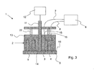
- Figure 3 shows the first embodiment of the sensor device 1 with a biasing device comprising two springs 22.
- the design of the electrodes 3, 4 and the abrasive device 9 shown in figures 1 a and 1 b implies that the surface area of the operative end surface 5 of the electrodes 3, 4 not being covered by the abrasive device 9 is constant in time during movement ( i.e. , rotation in the first embodiment) of the abrasive device 9.
- the surface area of the operative end surface 5 of the electrodes 3, 4 being exposed to a liquid during use of the sensor unit 1 remains constant independent of the angular position of the abrasive device 9.
- the surface area of the electrodes 3, 4 that is exposed to the liquid remains constant even as electrode material is slowly abraded.
- the first embodiment of the sensor device 1, or variants thereof may be varied (not shown) such that the probe comprises more than one working electrode.
- the probe may comprise any suitable number of annular working electrodes.
- Each working electrode then has an operative end surface being adapted to be arranged in contact with an electrically conductive liquid.
- all working electrodes and the auxiliary electrode are then embedded in the cylindrical support structure.
- each annular electrode has a non-embedded annular end surface forming the operative end surface. All annular electrodes have different diameters and are arranged concentric.
- the rotating axis passes through the cylindrical support structure in a gas tight feed-through being arranged concentric with the annular electrodes.
- the cylindrical support structure comprises one gas tight, and possibly liquid tight, electric feed-through for each electrode for electrical connection of the electrodes to the control unit by means of the electrical leads.
- control unit is connected to the working electrodes and the auxiliary electrode by electrical leads, whereby a closed circuit is formed when the operative end surface of the electrodes is in contact with an electrically conductive liquid.
- the control unit is in such variants arranged to apply a series of voltage pulses between each of the working electrodes and the auxiliary electrode. An electric current flows through the closed circuit as a response to an applied voltage pulse between one of the working electrodes and the auxiliary electrode.
- the control unit is further arranged to record a response signal corresponding to an electric current generated in the electric circuit in response to an applied voltage pulse.
- the working electrodes may be connected to a relay box, allowing each working electrode to be connected separately in a two-electrode configuration.
- the abrasive device is arranged in relation to the electrodes such that the operative end surface of all working electrodes and the auxiliary electrode is contacted by the abrading surface during rotation of the abrasive device so as to abrade contaminants thereon.
- the abrasive device has such a design and is arranged in relation to the electrodes that an abrading effect on the complete operative end surface of all working electrodes and the auxiliary electrode is achieved.
- the above described embodiments or variants thereof may be varied such that the electrodes have any other shape than annular.
- the support structure in which they are embedded may then have any other suitable shape than cylindrical.
- each electrode is in all these cases embedded such that one surface is non-embedded and forms the operative end surface.
- each working electrode is a metal wire (instead of being an annular electrode) embedded in a support structure.
- Each metal wire has a non-embedded end surface forming the operative end surface.
- the support structure is then rod-shaped and the auxiliary electrode is an annular electrode being arranged around the periphery of the rod-shaped support structure.
- the mounting means passes then through the rod-shaped support structure in a gas tight feed-through being arranged parallel to the longitudinal extension of the rod-shaped support structure.
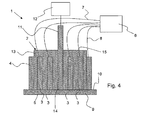
- FIG 4 One such variant is shown in figure 4 .
- figure 4 shows a second embodiment of the sensor device 1 according to the invention, which corresponds to the first embodiment shown in figure 1 a except for concerning the number of working electrodes that the probe comprises, the shape of the electrodes and the arrangement of the auxiliary electrode 4.
- the probe 2 comprises four working electrodes 3.
- Each working electrode 3 is a metal wire embedded in the support structure 13, whereby each metal wire 3 has a non-embedded end surface forming the operative end surface 5.
- the support structure 13 is rod-shaped and the auxiliary electrode 4 is an annular electrode being arranged around the periphery of the rod-shaped support structure 13.
- the mounting means 11 e.g. , the rotating axis, passes through the rod-shaped support structure 13 in a gas tight feed-through 14 being arranged parallel to the longitudinal extension of the rod-shaped support structure 13.
- the mounting means 11 may pass through the rod-shaped support structure 13 in any suitable way.
- control unit 6 is connected to the working electrodes 3 and the auxiliary electrode 4 by electrical leads 7, 8, whereby a closed circuit is formed when the operative end surface 5 of the electrodes 3, 4 is in contact with an electrically conductive liquid.
- the rod-shaped support structure 13 comprises one gas tight, and possibly liquid tight, electric feed-through 15 for each working electrode 3 for electrical connection of the electrodes 3 to the control unit 6 by means of the electrical leads 7.
- the control unit 6 is arranged to apply a series of voltage pulses between one working electrode 3 at a time and the auxiliary electrode 4. An electric current flows through the closed circuit as a response to an applied voltage pulse between one of the working electrodes 3 and the auxiliary electrode 4.
- the control unit 6 is further arranged to record a response signal corresponding to an electric current generated in the electric circuit in response to an applied voltage pulse.
- the working electrodes 3 may be connected to a relay box (not shown), allowing each working electrode 3 to be connected separately in a two-electrode configuration.
- the abrasive device 9 is arranged in relation to the electrodes 3, 4 such that the operative end surface 5 of all working electrodes 3 and the auxiliary electrode 4 is contacted by the abrading surface 10 during rotation of the abrasive device 9 so as to abrade contaminants thereon.
- the abrasive device 9 has such a design and is arranged in relation to the electrodes 3, 4 that an abrading effect on the complete operative end surface 5 of all working electrodes 3 and the auxiliary electrode 4 is achieved during rotation of the abrasive device 9.
- the second embodiment shown in figure 4 may of course be varied such that it comprises another number of working electrodes, i.e. , it may comprise one, two or three working electrodes or more than four working electrodes.
- the abrasive device is arranged in relation to the working electrode(s) and the auxiliary electrode such that the operative end surface of all electrodes is contacted by the abrading surface during rotation of the abrasive device.
- the second embodiment may be varied in accordance with any other variations of the first embodiment.
- it may further comprise a reference electrode, it may comprise a probe housing, it may comprise a probe mounting means and/or it may comprise a biasing device.
- the abrasive device is movable through rotation in relation to the operative end surface of the electrodes.
- the abrasive device may be movable in any other way than rotation in relation to the operative end surface of the electrodes.
- the mounting means may be any other mounting means than a rotating axis.
- the abrasive device may be moved by oscillation.
- the abrasive device has one abrading surface.
- it may likewise be designed to have more than one abrading surface.
- it may be designed such that it has one abrading surface for each electrode.
- the abrasive device has at least one abrading surface.
- the abrasive device is movable in a predetermined pattern in relation to the operative end surface of the electrodes and is arranged in relation to the electrodes such that the operative end surface of each electrode is contacted by at least one of the abrading surfaces during movement of the abrasive device in the predetermined pattern so as to abrade contaminants bound thereon.
- the abrasive device may be arranged to be continuously or intermittently moved in the predetermined pattern such that a continuous or intermittent abrading of contaminants bound to said operative end surface of the electrodes is achieved, whereby fluctuations of the response signal are reduced.
- the abrasive device is mounted on a mounting means via which said abrasive device is connectable to a drive unit for driving the movement of the abrasive device.
- the abrading surface(s) of the abrasive device of any of the above embodiments may be a grinding stone surface, i.e. , the abrasive device may be a grinding stone.
- the abrading surface(s) may be of any other suitable material that may exert an abrasive effect on the operative end surface of the electrodes, e.g. , a rubber-like material containing abrasive particles.
- the auxiliary electrode of the sensor device according to the invention is made of stainless steel.
- other materials are of course also conceivable, e.g. , Pt, Au.
- the working electrode(s) may, e.g. , be made of a material selected from the group consisting of Rh, Pt, Au, Os, Ru, Ni, Ti, Re, Ir and alloys thereof, or alloys with other metals.
- the auxiliary electrode and the working electrode(s) are preferably made of materials having essentially the same hardness such that the electrodes have essentially the same hardness. Thereby the abrading surface(s) will abrade essentially equally on the operative end surface of the different electrodes.
- the working electrode is made of an alloy of Pt and Ir ( e.g. , in the ratio of 90:10) and that the auxiliary electrode is made of stainless steel.
- one working electrode is made of an alloy of Pt and Ir ( e.g. , in the ratio of 90:10), that the other working electrode is made of Au and that the auxiliary electrode is made of stainless steel.
- an Ag/AgCl KCI 3M
- KCI 3M Ag/AgCl
- the present invention relates to a system for monitoring an anaerobic digestion process (e.g. , a biogas production process) in an electrically conductive liquid comprising organic material.
- the system according to the invention comprises any of the above described embodiments or variants of the sensor device according to the invention and
- the control unit records an amount of electric current values.
- This amount of data may be stored in the memory for storing recorded electric current values. Then the data may be analyzed by means of performing a multivariate data analysis of the stored electric current values and the display device may display the results.
- the system according to the invention may further comprise a sampling device for sampling values of the response signal at predetermined intervals.
- the memory for storing recorded values, the processing device and the display device may be comprised in the same unit, such as, e.g. , a personal computer (PC). Alternatively, they may be comprised in separate units.
- a system 20 according to the invention which comprises a personal computer 21 and the first embodiment of the sensor device 1 is shown in figure 5 .
- the personal computer 21 comprises a memory for storing recorded electric current values in a data matrix, a processing device for performing a multivariate data analysis of the stored electric current values and a display device for displaying the result of the multivariate data analysis.
- measurements may be performed on the sludge in a main digester, on the sludge in a bypass of the main digester, on the feed or on the residue. Furthermore, measurements may be performed on-line by means of the sensor device according to the invention. Measurements by means of the sensor device according to the invention may be combined with pH, redox potential, alkalinity, gas yield, gas composition, turbidity measurements, etc. and measurements of total solids by means of any other suitable measurement devices. Furthermore, the present invention relates to a method for monitoring an anaerobic digestion process (e.g. , a biogas production process) in an electrically conductive liquid comprising organic material. The method comprises the steps of:
- the abrading may e.g., be performed before or during the step for applying a series of voltage pulses and the step for recording a response signal.
- the abrading is performed by means of an abrasive device having at least one abrading surface, whereby the abrasive device is movable in a predetermined pattern in relation to the operative end surface of the electrodes and is arranged in relation to the electrodes such that the operative end surface of each electrode is contacted by at least one of the abrading surfaces during movement of the abrasive device in the predetermined pattern so as to abrade contaminants bound thereon.
- fluctuations of the response signal are reduced.
- the method according to the invention may further comprise the steps of:
- the response signals may be analyzed using a previously known analysis method called multivariate data analysis.
- multivariate data analysis methods There are many different multivariate data analysis methods that may be utilized in the present invention.
- Principal component analysis (PCA) is proposed as a general tool to provide an overview of the relatively large amount of measured data as well as a tool for determining qualitative information about the measured samples.
- Partial least squares (PLS), multiple linear regression (MLR), and principal component regression (PCR) are proposed as tools for linear regression to determine quantitative information about the measured samples.
- Artificial neural networks (ANN) and project pursuit regression (PPR) are proposed as tools for non-linear regression to determine quantitative information about the measured samples. All these algorithms are well known and detailed descriptions of them may be found in numerous commonly-available books and articles.
- the international applications WO 99/13325 , WO 02/44460 and WO 02/052254 describe multivariate data analysis methods.
- System identification distinguishes between parametric and non-parametric (black-box) models.
- parametric models assumes some a priori knowledge about the studied system. Given the complexity of anaerobic digestion processes, non-parametric models may be more suitable.
- Some well-known algorithms for estimation of linear non-parametric models are autoregressive models (ARX, ARMAX), Box-Jenkins (BJ) models, and output-error (OE) models.
- ARX autoregressive models
- BJ Box-Jenkins
- OE output-error
- the result of the analysis may be utilized in order to monitor an anaerobic digestion process. More specifically, by analyzing the recorded signals at different points in time by means of any of the above methods and compare the results of the analysis, it is possible to monitor an anaerobic digestion process. In case the result of the analysis of the signals recorded at different points in time differ, this indicates that the process has changed in some way, i.e. , that a property of the process has changed. Thus, the analyzed signals provide real-time information about the stability of the process. This will be further described below in connection with the experiments. Alternatively, the results of the analysis of the recorded signals may be compared with reference data to determine the current process status.
- the stability and yield of an anaerobic process may be monitored.
- the normal operation of the process may thereby be verified and any process abnormalities may be identified.
- the results may be presented to a plant operator, who may react to any abnormality, e.g. , by changing the substrate feeding strategy.
- a general advantage with the present invention is that it allows the use of a single probe to detect and determine many different physical and chemical properties of the liquids in anaerobic digestion processes.
- the alternative would be to use multiple sensors, one for each of the properties of interest. Given the complexity of these processes and the large number of (interdependent) properties that affect the processes, the latter approach becomes too complex and expensive.
- a prior art sensor device comprising a probe and a control unit were utilized in order to test the applicability of a prior art sensor device for monitoring a biogas production process.
- the sensor device utilized in the first experiment corresponded to the sensor device shown in figure 4 , but without the abrasive device 9, the mounting means 11, the drive unit 12, the feed-through 14 for the mounting means 11 and the probe housing 16.
- the four working electrodes 3 were made of gold (Au), iridium (Ir), platinum (Pt), and rhodium (Rh), respectively, and the auxiliary electrode 4 was made of stainless steel.
- the utilized control unit included a pulse generating part arranged to generate voltage pulses of varying amplitude and duration.
- the control unit also comprised a current measuring part arranged to measure the current at the working electrode by feeding it to a current measuring circuit being sampled at a specific frequency.
- the pulse generating part and the current measuring part were both galvanically isolated from the power system to which the control unit was connected, meaning they could be operated both in a grounded system or an ungrounded system.
- a 5 liter glass bottle reactor was utilized as reactor and organic material in the form of slaughterhouse waste was utilized as substrate.
- the slaughterhouse waste was blended with distilled water in order to form a substrate slurry.
- the slurry comprised an electrically conductive liquid comprising organic material.
- the experiment was run at 37 oC. At each feeding instance (once per day), 150 ml of new substrate slurry was put into the reactor, while an equal amount of digested sludge was removed.
- the probe was mounted in the reactor from the top by passing the signal cables through a plastic tube going through a rubber plug, and sealing it with tape on the outside.
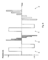
- the series of voltage pulses shown in figure 6 was then applied by means of the control unit to the working electrodes in series, meaning that a complete series of voltage pulses was applied to the first working electrode before being applied to the second working electrode and so on.
- Each complete series of voltage pulses comprise four different sections A, B, C and D respectively, differing in both voltage amplitudes and pulse durations (see figure 6 ).
- the voltage amplitudes are correctly depicted in figure 6 whereas the pulse durations shown are not to scale.
- the pulse durations were as follows: A: 1000 ms, B: 25 ms; C: 1000 ms and D: 250 ms.
- FIG. 8 shows the response signal from the working electrodes recorded by the control unit at one particular potential as a function of time. From figure 8 it is clear that the accumulation of gas bubbles on the surface of the working electrodes and the concomitant signal drop are no longer a problem when stirring continuously. However, several days after the insertion of a probe with freshly cleaned electrodes the measured signals become unstable. This effect is due to fouling of the electrodes by the reactor sludge and depends on the choice of electrode material. As compared with gold, iridium, and rhodium, platinum and platinum/iridium (90/10) electrodes have been found to be more stable against fouling.
- a sensor device corresponding to the sensor device shown in figure 1 a was utilized.
- the abrasive device 9 was designed such that an abrading effect was achieved only on the working electrode 3, i.e. , the abrasive device 9 did not contact the auxiliary electrode 4.
- the working electrode 3 was made of platinum and the auxiliary electrode 4 was made of stainless steel.
- the same control unit as in the first experiment was utilized as control unit 6.
- a motor of the type Berger-Lahr RSM was utilized as drive unit 12.
- a silicon carbide grinding stone was utilized as abrasive device.
- a 227 liter plastic barrel reactor was utilized as reactor and organic material in the form of stillage from fermentative ethanol production was utilized as substrate.
- the substrate was taken from a pilot plant that had been in operation for several months, thus eliminating the need for a prolonged start-up phase of the process.
- the stillage was used as substrate without prior blending with a liquid as it comprised an electrically conductive liquid with organic material.
- the experiment was run at 37 oC. At each feeding instance, 5 liter of new substrate was put into the reactor, while an equal amount of digested sludge was removed. Feeding of new substrate was carried out once a day during weekdays, whereas no feeding was performed during weekends.
- the reactor content was mixed only during feeding instances by pumping the liquid for a short period of time in a circular bypass loop.
- the probe was mounted in the reactor from the top using a flange that was sealed with a Viton® o-ring.
- the series of voltage pulses shown in figure 6 and described in connection with the first experiment was then applied by means of the control unit to the working electrodes.
- the grinding stone was rotated by 10 revolutions per minute. Measurement signals were recorded at an interval of 15 seconds.
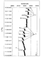
- Figure 9 shows the measured response signal at one particular potential as a function of time for the third experiment during operation over a period of 13 days. It is evident from figure 9 that the addition of new substrate to the reactor has a significant effect on the measurement signals.
- “A” denotes feedings during week 1 (Tue - Fri)
- “B” denotes feedings during week 2 (Mon - Fri)
- “C” denotes manual cleaning of the auxiliary electrode. It may be seen that no signal instabilities occur due to sticking gas or fouling electrodes.
- the periodic dips in the signal correspond to the daily feeding of the reactor during working days. The signal is largely recurring between the feeding instances and characterized by a rather rapid decrease that is followed by a gradual recovery.
- the general decrease of the signal seen during the first week is due to process drift during the start-up phase of the reactor.
- the sharp decrease in the signal seen towards the end of the measurement period is due to manual cleaning of the auxiliary electrode. This clearly illustrates the need of also continuously cleaning the auxiliary electrode.
- the above experiment illustrates how the invention may be utilized in order to enable monitoring of a biogas production process.
- One suitable way of presenting the measurement results to the process operator is using multivariate-statistics algorithms that reduce the dimensionality of the measured data, such as PCA.
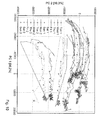
- the principle is outlined in figure 10 , which shows a PCA score plot calculated from the signal responses measured in the above-mentioned 227 liter barrel reactor experiment.
- a PCA model was generated using measurements from 4 days. The measured signal responses recorded for each day were then projected onto the generated PCA model to form the shown score plot along the first two principal components PC1 and PC2.
- the observed pattern is similar for each day of fermentation: starting from a cluster of measurement points prior to feeding, a rapid shift towards decreasing PC1 within 2-3 hours after feeding, which is followed by a slow movement of the measurement points in the direction of increasing PC1 back to the original cluster, ending up in the formation of a larger cluster of measurement points until the next feeding instance.
- the measurement points move slowly in the direction of increasing PC2.
- the measurement points move slowly in the direction of increasing PC1.
- the score plot is thus indicating higher metabolic activity of the microorganisms in the direction of decreasing PC1.
- the slow drift along the direction of increasing PC2 is not caused by the fouling of the auxiliary electrode mentioned above, since the manual cleaning of the auxiliary electrode performed at the end of the measurement period caused an abrupt jump along the direction of increasing PC1 only. Rather, the drift along PC2 provides a measure for the stability of the process, such that main clusters for each day of fermentation that end up on top of each other would indicate a stable process.
- the score plot updated in real-time during the process, thus provides a means for the plant operator to monitor the evolution of the process and confirm the activity and stability.
- a fourth biogas process experiment was performed in order to confirm the ability of the measurements to react to different feeding conditions.
- two 5 liter glass bottle reactors (denoted as reactor A and reactor B) were utilized and organic material in the form of slaughterhouse waste was utilized as substrate.
- the slaughterhouse waste was blended with distilled water in order to form a substrate slurry.
- the slurry formed an electrically conductive liquid comprising organic material.
- 150 ml of new substrate was put into the reactor while an equal amount of digested sludge was removed.
- the experiments were performed at 37 oC with continuous stirring of the content in the reactors. Stirring was achieved by rotating a stainless steel rod equipped with four propeller-like metallic blades at the lower end.
- the rod was inserted to the reactor from the top through a plastic tube going through the centre of a rubber plug. Outside of the reactor the top end of the rod was mounted to an electric motor.
- the electrochemical probe used contained four working electrodes made of Ir, Rh, Pt/Ir (90/10) and Pt/Ir (90/10), respectively, and an auxiliary electrode made of stainless steel.
- the sensor device utilized in the fourth experiment corresponded to the sensor device shown in figure 4 , but without the abrasive device 9, the mounting means 11, the drive unit 12, the feed-through 14 for the mounting means 11 and the probe housing 16.
- the same control unit as in the first experiment was utilized as the control unit 6. Measurement signals were recorded at an interval of 15 seconds.
- Figures 11 a and 11 b show the measured response signal from one of the Pt/Ir electrodes at one particular potential as a function of time for reactor A and reactor B, respectively, during operation over a period of 3 days.
- the two reactors, reactor A and reactor B were operated under normal feeding conditions with feeding performed once a day, but on one occasion, reactor B was subjected to a forced feeding scheme whereby extra butyric and propionic acid was added.
- the amounts of extra acid were chosen such that the acid concentrations in reactor B directly after feeding would be 50 mM for butyric acid and 25 mM for propionic acid, respectively, which for the studied process corresponds to a significant but not extreme increase of the concentration of acids.
- the measured signals may be used to determine quantitative regression models for on-line estimation of the concentration of VFAs in the liquid phase at various positions in anaerobic digestion plants, using linear regression algorithms such as PLS or non-linear algorithms such as ANN. Given the electrochemical differences between different VFAs and that the relative signal changes due to the extra feeding differs for different potentials, it is conceivable that separate regression models may be determined for the concentration of individual VFAs.
- the measurement technology, the sensor device and the system according to the invention may also be utilized to model ( i.e. , estimate) a key process parameter that is characteristic for the status or performance of the anaerobic digestion process.
- the measurement technology of the present invention it is likely that it may be used to estimate also other key process parameters in anaerobic digestion processes such as the redox potential and the alkalinity. In the latter case, it may be an advantage to complement the measurements with on-line data from a pH probe. Furthermore, it has been shown that the measurement technology may be used to estimate the chemical oxygen demand (COD) in waste water. Thus, the measurements may be used to determine the COD of the substrate fed to the process, the reactor sludge, and the digested sludge removed from the process.
- COD chemical oxygen demand
- the product yield e.g. , biogas or hydrogen
- the product yield which may be measured directly, is a suitable control parameter in combination with an overriding alarm parameter such as VFA concentration, alkalinity, or pH (see, e.g. , Boe et al, 2007).
- an overriding alarm parameter such as VFA concentration, alkalinity, or pH (see, e.g. , Boe et al, 2007).
- the need for the extra alarm parameter is related to the fact that the product yield may stay high even when the process is approaching unstable conditions.
- measurements according to the present invention have been shown to contain information about the stability and microbial activity and both the current and future productivity are related to the status of the bioreactor sludge and the activity, estimated values for the product yield at an offset future point in time may be suitable for on-line process control without the need for an additional overriding alarm.
- measurements may be made on the liquid phase at suitable positions in an anaerobic digestion plant.
- the signals may then be utilized for on-line estimation of key process parameters and the estimated process parameters may be used for on-line control of the anaerobic digestion process.
- concentration of (individual) VFAs or the alkalinity to control such processes is partly due to the large complexity and limited speed of accurate measurement methods for these parameters and the low accuracy of quick and simple measurement methods.
- VFA and alkalinity measurements according to the present invention are very promising for on-line control of anaerobic digestion process since they are quite simple yet capable of a relatively high accuracy.
- On-line feed-control strategies may also benefit from on-line measurements of the feed quality, e.g. , organic dry matter and biochemical methane potential, and of the properties of the digested sludge, e.g. , the remaining organic dry matter.
- This is another area where measurements according to the present invention are promising. Although these measurements mainly provide information about dissolved constituents, complementary information may be obtained from parallel measurements of, e.g. , turbidity or total suspended solids.
- anaerobic digestion processes using the raw measurement signals as input to multivariate statistical process control algorithms instead of using estimated key parameters. This may be performed in order to improve the stability and/or efficiency of the anaerobic digestion processes, e.g. , by controlling the hydraulic retention time or the addition of specific organic materials that are known to exert a direct influence on specific process parameters during fermentation. Also in these cases, it may be advantageous to complement the measured pulse voltammetry data with parallel data from other measurements such as pH, turbidity or total solids.
Landscapes
- Chemical & Material Sciences (AREA)
- Life Sciences & Earth Sciences (AREA)
- Health & Medical Sciences (AREA)
- Physics & Mathematics (AREA)
- Chemical Kinetics & Catalysis (AREA)
- Electrochemistry (AREA)
- Molecular Biology (AREA)
- Analytical Chemistry (AREA)
- Biochemistry (AREA)
- General Health & Medical Sciences (AREA)
- General Physics & Mathematics (AREA)
- Immunology (AREA)
- Pathology (AREA)
- Investigating Or Analyzing Materials By The Use Of Electric Means (AREA)
- Treatment Of Sludge (AREA)
Claims (14)
- Sensorvorrichtung (1) zum Überwachen eines anaeroben Ausfäulungsprozesses in einer elektrisch leitenden Flüssigkeit, die organisches Material umfasst, wobei die Sensorvorrichtung (1) umfasst:- einen Messfühler (2), der mindestens eine Arbeitselektrode (3) und eine Hilfselektrode (4) umfasst; und- eine Steuereinheit (6);wobei die Steuereinheit (6) angeordnet ist, um eine Serie von Spannungspulsen zwischen der mindestens einen Arbeitselektrode (3) und der Hilfselektrode (4) anzuwenden, wobei jede der Elektroden (3, 4) eine operative Endoberfläche (5) hat, welche eingerichtet ist, um in Berührung mit der Flüssigkeit angeordnet zu werden, um derart einen elektrischen Schaltkreis auszubilden, und wobei die Steuereinheit (6) weiterhin angeordnet ist, um ein abhängiges Signal aufzuzeichnen, welches einem elektrischen Strom entspricht, der in dem elektrischen Schaltkreis abhängig von einem angewendeten Spannungspuls erzeugt wird,
dadurch gekennzeichnet, dass
die Sensorvorrichtung (1) weiterhin eine Schleifvorrichtung (9) umfasst, welche mindestens eine Schleifoberfläche (10) hat, wobei die Schleifvorrichtung (9) in einem vorbestimmten Muster in Bezug auf die operative Endoberfläche (5) der Elektroden (3, 4) bewegbar ist und derart in Bezug auf die Elektroden (3, 4) angeordnet ist, dass die operative Endoberfläche (5) jeder Elektrode (3, 4) von mindestens einer der Schleifoberflächen (10) während Bewegung der Schleifvorrichtung (9) in dem vorbestimmten Muster berührt wird, um derart darauf gebundene Verunreinigungen abzuschleifen, wobei die Schleifvorrichtung (9) auf einem Befestigungsmittel (11) befestigt ist, mittels welchem die Schleifvorrichtung (9) mit einer Antriebseinheit (12) zum Antreiben der Bewegung der Schleifvorrichtung (9) verbunden werden kann. - Sensorvorrichtung (1) nach Anspruch 1, dadurch gekennzeichnet, dass die Schleifvorrichtung (9) angeordnet ist, um kontinuierlich oder unterbrochen in dem vorbestimmten Muster bewegt zu werden, so dass Abschleifen von Verunreinigungen, die auf der operativen Endoberfläche (5) der Elektroden (3, 4) gebunden sind, erreicht wird.
- Sensorvorrichtung (1) nach Anspruch 1 oder 2, dadurch gekennzeichnet,
dass die Elektroden (3, 4) ringförmige Elektroden sind, welche in eine zylindrische Stützstruktur (13) eines elektrisch isolierenden Materials eingebettet sind, wobei jede ringförmige Elektrode (3, 4) nicht eingebettete ringförmige Endoberflächen hat, welche die operative Endoberfläche (5) ausbilden, wobei die ringförmigen Elektroden (3, 4) unterschiedliche Durchmesser haben und konzentrisch angeordnet sind, und dass das Befestigungsmittel (11) durch die zylindrische Stützstruktur (13) in einer gasdichten Durchführung (14) zur Verbindung der Schleifvorrichtung (9) mit der Antriebseinheit (12) hindurchführt, wobei die gasdichte Durchführung (14) parallel zu der Längsausdehnung der zylindrischen Stützstruktur (13) angeordnet ist. - Sensorvorrichtung (1) nach Anspruch 1 oder 2, dadurch gekennzeichnet,
dass jede Arbeitselektrode (3) ein in einer stabförmigen Stützstruktur (13) eingebetteter Metalldraht ist, wobei jeder Metalldraht eine nicht eingebettete Endoberfläche hat, welche die operative Endoberfläche (5) ausbildet, und
dass die Hilfselektrode (4) eine um den Umfang der stabförmigen Stützstruktur (13) herum angeordnete ringförmige Elektrode ist, und
dass das Befestigungsmittel (11) durch die stabförmige Stützstruktur (13) in einer gasdichten Durchführung (14) zur Verbindung der Schleifvorrichtung (9) mit der Antriebseinheit (12) hindurchführt, wobei die gasdichte Durchführung (14) parallel zu der Längsausdehnung der stabförmigen Stützstruktur (13) angeordnet ist. - Sensorvorrichtung (1) nach einem der Ansprüche 1-4, dadurch gekennzeichnet, dass das Befestigungsmittel (11) eine rotierende Achse ist, wobei die Schleifvorrichtung (9) durch Rotation in Bezug auf die operative Endoberfläche (5) der Elektroden (3, 4) bewegbar ist und in Bezug auf Elektroden (3, 4) derart angeordnet ist, dass die operative Endoberfläche (5) jeder Elektrode (3, 4) von mindestens einer der mindestens einen Schleifoberfläche (10) während Rotation der Schleifvorrichtung (9) berührt wird, um derart darauf gebundene Verunreinigungen abzuschleifen.
- Sensorvorrichtung (1) nach einem der voranstehenden Ansprüche, dadurch gekennzeichnet, dass jede Schleifoberfläche (10) eine Mahlsteinoberfläche ist.
- Sensorvorrichtung (1) nach einem der voranstehenden Ansprüche, dadurch gekennzeichnet, dass die Elektroden (3, 4) im Wesentlichen gleiche Härte haben.
- Sensorvorrichtung (1) nach Anspruch 7, dadurch gekennzeichnet, dass die Sensorvorrichtung (1) nur eine Arbeitelektrode (3) umfasst, wobei die Arbeitselektrode (3) aus einer Legierung aus Platin und Iridium gemacht ist und die Hilfselektrode (3) aus Edelstahl gemacht ist.
- Sensorvorrichtung (1) nach Anspruch 7, dadurch gekennzeichnet, dass die Sensorvorrichtung (1) zwei Arbeitselektroden (3) umfasst, wobei eine Arbeitselektrode (3) aus einer Legierung aus Platin und Iridium gemacht ist, eine Arbeitselektrode (3) aus Gold gemacht ist und die Hilfselektrode (4) aus Edelstahl gemacht ist.
- Sensorvorrichtung (1) nach einem der voranstehenden Ansprüche,
dadurch gekennzeichnet, dass die Sensorvorrichtung (1) weiterhin die Antriebseinheit (12) umfasst, wobei die Antriebseinheit (12) eingerichtet ist, um außerhalb des Messfühlers (2) angeordnet zu werden. - Sensorvorrichtung (1) nach einem der Ansprüche 1-9, dadurch gekennzeichnet, dass die Sensorvorrichtung (1) weiterhin die Antriebseinheit (12) umfasst, wobei der Messfühler (2) ein gasdichtes Messfühlergehäuse (16) umfasst, wobei die Stützstruktur (13) mit den Elektroden (3, 4) gasdicht in einer Öffnung (17) des Messfühlergehäuses (16) derart angeordnet ist, dass die operative Endoberfläche (5) der Elektroden (3, 4) eingerichtet ist, um in Berührung mit der Flüssigkeit angeordnet zu sein, und wobei die Antriebseinheit (12) innerhalb des Messfühlergehäuses (16) angeordnet ist.
- System (20) zum Überwachen eines anaeroben Ausfäulungsprozesses in einer elektrisch leitenden Flüssigkeit, die organisches Material umfasst, dadurch gekennzeichnet, dass das System umfasst:- eine Sensorvorrichtung (1) nach einem der Ansprüche 1-11;- eine Speicher zum Sichern von mindestens einigen aufgezeichneten elektrischen Stromwerten in einer Datenmatrix;- eine Prozessorvorrichtung zum Ausführen einer multivariaten Datenanalyse der gesicherten elektrischen Stromwerte; und- optional, eine Bildschirmvorrichtung zum Wiedergeben des Ergebnisses der multivariaten Datenanalyse.
- Verfahren zum Überwachen eines anaeroben Ausfäulungsprozesses in einer elektrisch leitenden Flüssigkeit, die organisches Material umfasst, wobei das Verfahren die Schritte umfasst:- Anwenden einer Serie von Spannungspulsen mittels einer Steuereinheit (6) zwischen mindestens einer Arbeitselektrode (3) und einer Hilfselektrode (4), wobei jede Elektrode (3, 4) eine operative Endoberfläche (5) hat, welche in Berührung mit der Flüssigkeit derart angeordnet ist, dass sie einen elektrischen Schaltkreis ausbildet; und- Aufzeichnen eines abhängigen Signals, welches einem elektrischen Strom entspricht, der in dem elektrischen Schaltkreis abhängig von einer angewendeten Serie von Spannungspulsen erzeugt wird, wobei das abhängige Signal mittels der Steuereinheit (6) aufgezeichnet wird; dadurch gekennzeichnet, dassVerunreinigungen, welche an die operative Endoberfläche (5) der Elektroden (3, 4) gebunden sind, abgeschliffen werden, wobei das Abschleifen mittels einer Schleifvorrichtung (9) mit mindestens einer Schleifoberfläche (10) durchgeführt wird, wobei die Schleifvorrichtung (9) in einem vorbestimmten Muster in Bezug auf die operative Endoberfläche (5) der Elektroden (3, 4) bewegbar ist und in Bezug auf die Elektroden (3, 4) derart angeordnet ist, dass die operative Endoberfläche (5) jeder Elektrode (3, 4) von mindestens einer der Schleifoberflächen (10) während Bewegung der Schleifvorrichtung (9) in dem vorbestimmten Muster berührt wird, um derart darauf gebundene Verunreinigungen abzuschleifen.
- Verfahren nach Anspruch 13, dadurch gekennzeichnet, dass
das Verfahren weiterhin die Schritte umfasst:- Sichern mindestens einiger aufgezeichneter Stromwerte in einem Speicher; und- Durchführen einer multivariaten Datenanalyse der gesicherten elektrischen Stromwerte mittels einer Prozessorvorrichtung.
Priority Applications (4)
| Application Number | Priority Date | Filing Date | Title |
|---|---|---|---|
| AT08154460T ATE552495T1 (de) | 2008-04-14 | 2008-04-14 | Sensorvorrichtung, system und verfahren zur kontrolle eines anaeroben verdauungsprozesses |
| PL08154460T PL2110660T3 (pl) | 2008-04-14 | 2008-04-14 | Urządzenie czujnikowe, system i sposób monitorowania procesu fermentacji beztlenowej |
| ES08154460T ES2385508T3 (es) | 2008-04-14 | 2008-04-14 | Dispositivo sensor, sistema y método para supervisar un proceso de digestión anaeróbica |
| EP08154460A EP2110660B1 (de) | 2008-04-14 | 2008-04-14 | Sensorvorrichtung, System und Verfahren zur Kontrolle eines anaeroben Verdauungsprozesses |
Applications Claiming Priority (1)
| Application Number | Priority Date | Filing Date | Title |
|---|---|---|---|
| EP08154460A EP2110660B1 (de) | 2008-04-14 | 2008-04-14 | Sensorvorrichtung, System und Verfahren zur Kontrolle eines anaeroben Verdauungsprozesses |
Publications (2)
| Publication Number | Publication Date |
|---|---|
| EP2110660A1 EP2110660A1 (de) | 2009-10-21 |
| EP2110660B1 true EP2110660B1 (de) | 2012-04-04 |
Family
ID=39768685
Family Applications (1)
| Application Number | Title | Priority Date | Filing Date |
|---|---|---|---|
| EP08154460A Not-in-force EP2110660B1 (de) | 2008-04-14 | 2008-04-14 | Sensorvorrichtung, System und Verfahren zur Kontrolle eines anaeroben Verdauungsprozesses |
Country Status (4)
| Country | Link |
|---|---|
| EP (1) | EP2110660B1 (de) |
| AT (1) | ATE552495T1 (de) |
| ES (1) | ES2385508T3 (de) |
| PL (1) | PL2110660T3 (de) |
Families Citing this family (8)
| Publication number | Priority date | Publication date | Assignee | Title |
|---|---|---|---|---|
| AT12618U1 (de) * | 2011-05-30 | 2012-08-15 | Gilhofer Andree Mag | Verfahren und vorrichtung zu einer von ausserhalb möglichen wartung, reinigung und kalibrierung von elektroanalytischen messeinrichtungen in gülle |
| WO2013016438A2 (en) | 2011-07-26 | 2013-01-31 | General Electric Company | Wastewater treatment plant online monitoring and control |
| PL2579032T3 (pl) * | 2011-10-07 | 2015-10-30 | General Electric Technology Gmbh | Czujnik siarczynu i sposób pomiaru stężenia siarczynu w substancji |
| CN102680164B (zh) * | 2012-05-08 | 2013-12-18 | 中国科学技术大学 | 一种厌氧反应器的在线监测系统 |
| EA201591006A1 (ru) * | 2012-12-28 | 2015-11-30 | Оутотек (Финлэнд) Ой | Способ и устройство для мониторинга качества руды |
| EP3104171B1 (de) | 2015-06-12 | 2018-08-22 | General Electric Technology GmbH | Sensor für dibasische säuren und verfahren zur kontinuierlichen messung der konzentration dibasischer säuren in einer substanz |
| CN109632550B (zh) * | 2018-12-24 | 2022-01-14 | 长安大学 | 一种磨耗性能对比试验装置及试验方法 |
| CN113008954B (zh) * | 2021-03-03 | 2023-03-21 | 浙江农林大学 | 一种检测葡萄糖、果糖、蔗糖混合溶液浓度的方法 |
Family Cites Families (4)
| Publication number | Priority date | Publication date | Assignee | Title |
|---|---|---|---|---|
| SE518437C2 (sv) | 1997-09-07 | 2002-10-08 | Appliedsensor Sweden Ab | Elektronisk tunga |
| US6235123B1 (en) * | 1998-05-04 | 2001-05-22 | Honeywell-Measorek Corporation | Chemical cleaning system for electrodes used in a liquid environment |
| SE517992C2 (sv) | 2000-11-29 | 2002-08-13 | Asko Cylinda Ab | Metod för rengöring av tvätt/diskgods i en tvätt/diskmaskin och anordning för genomförande av metoden |
| TW552415B (en) | 2000-12-22 | 2003-09-11 | Otre Ab | Electronic tongue as ozone detector |
-
2008
- 2008-04-14 AT AT08154460T patent/ATE552495T1/de active
- 2008-04-14 ES ES08154460T patent/ES2385508T3/es active Active
- 2008-04-14 PL PL08154460T patent/PL2110660T3/pl unknown
- 2008-04-14 EP EP08154460A patent/EP2110660B1/de not_active Not-in-force
Also Published As
| Publication number | Publication date |
|---|---|
| ES2385508T3 (es) | 2012-07-25 |
| PL2110660T3 (pl) | 2012-09-28 |
| ATE552495T1 (de) | 2012-04-15 |
| EP2110660A1 (de) | 2009-10-21 |
Similar Documents
| Publication | Publication Date | Title |
|---|---|---|
| EP2110660A1 (de) | Sensorvorrichtung, System und Verfahren zur Kontrolle eines anaeroben Verdauungsprozesses | |
| Jimenez et al. | Instrumentation and control of anaerobic digestion processes: a review and some research challenges | |
| Drosg | Process monitoring in biogas plants | |
| Pind et al. | Monitoring and control of anaerobic reactors | |
| Drosg et al. | Analysis and characterisation of biogas feedstocks | |
| Spanjers et al. | Instrumentation in anaerobic treatment–research and practice | |
| Larsen et al. | Fast responding biosensor for on-line determination of nitrate/nitrite in activated sludge | |
| US11753612B2 (en) | Control of bioreactor processes | |
| US6143246A (en) | Apparatus for measuring ammonia in biochemical processes | |
| EP3867349B1 (de) | Verfahren zur automatischen überwachung von biogasreaktoren | |
| Strong et al. | An in situ dissolved‐hydrogen probe for monitoring anaerobic digesters under overload conditions | |
| Li et al. | Online conductimetric flow-through analyzer based on membrane diffusion for ammonia control in wastewater treatment process | |
| Dong et al. | Novel online monitoring and alert system for anaerobic digestion reactors | |
| Feito et al. | Real-time monitoring of volatile fatty acids using a novel VFAs analyser and automated high solids separation system | |
| KR100499830B1 (ko) | 유체에서생물학적활성도를모니터하기위한방법 | |
| Simeonov et al. | Modelling and dynamic compensator control of the anaerobic digestion of organic wastes | |
| Tahkoniemi et al. | Fermentation reactor coupled with capillary electrophoresis for on-line bioprocess monitoring | |
| Ritzka et al. | Fermentation monitoring and process control | |
| Bernacchi et al. | Challenges and solutions for development of gas limited bioprocesses illustrated by the biological methane production (BMP) process development | |
| Kujawski et al. | Development of instrumentation systems as a base for control of digestion process stability in full-scale agricultural and industrial biogas plants | |
| WO2022065294A1 (ja) | 廃棄物処理システム、及び廃棄物処理方法 | |
| McMurray et al. | Integration of titrimetric measurement, off-gas analysis and NOx− biosensors to investigate the complexity of denitrification processes | |
| Jolicoeur et al. | Flow microcalorimetry in monitoring biological activity of aerobic and anaerobic wastewater-treatment processes | |
| Kasulla et al. | Process monitoring of biogas projects | |
| Vyrides et al. | Next generation techniques for anaerobic bioprocess optimization |
Legal Events
| Date | Code | Title | Description |
|---|---|---|---|
| PUAI | Public reference made under article 153(3) epc to a published international application that has entered the european phase |
Free format text: ORIGINAL CODE: 0009012 |
|
| AK | Designated contracting states |
Kind code of ref document: A1 Designated state(s): AT BE BG CH CY CZ DE DK EE ES FI FR GB GR HR HU IE IS IT LI LT LU LV MC MT NL NO PL PT RO SE SI SK TR |
|
| AX | Request for extension of the european patent |
Extension state: AL BA MK RS |
|
| RAP1 | Party data changed (applicant data changed or rights of an application transferred) |
Owner name: WIKA ALEXANDER WIEGAND SE & CO. KG |
|
| 17P | Request for examination filed |
Effective date: 20100414 |
|
| AKX | Designation fees paid |
Designated state(s): AT BE BG CH CY CZ DE DK EE ES FI FR GB GR HR HU IE IS IT LI LT LU LV MC MT NL NO PL PT RO SE SI SK TR |
|
| GRAP | Despatch of communication of intention to grant a patent |
Free format text: ORIGINAL CODE: EPIDOSNIGR1 |
|
| RIN1 | Information on inventor provided before grant (corrected) |
Inventor name: BACHINGER, THOMAS Inventor name: LOUTHANDER, DAN Inventor name: GAWRONSKI, MICHAEL Inventor name: MARTENSSON, PER |
|
| GRAS | Grant fee paid |
Free format text: ORIGINAL CODE: EPIDOSNIGR3 |
|
| GRAA | (expected) grant |
Free format text: ORIGINAL CODE: 0009210 |
|
| AK | Designated contracting states |
Kind code of ref document: B1 Designated state(s): AT BE BG CH CY CZ DE DK EE ES FI FR GB GR HR HU IE IS IT LI LT LU LV MC MT NL NO PL PT RO SE SI SK TR |
|
| REG | Reference to a national code |
Ref country code: GB Ref legal event code: FG4D |
|
| REG | Reference to a national code |
Ref country code: CH Ref legal event code: EP |
|
| REG | Reference to a national code |
Ref country code: AT Ref legal event code: REF Ref document number: 552495 Country of ref document: AT Kind code of ref document: T Effective date: 20120415 |
|
| REG | Reference to a national code |
Ref country code: IE Ref legal event code: FG4D |
|
| REG | Reference to a national code |
Ref country code: DE Ref legal event code: R096 Ref document number: 602008014572 Country of ref document: DE Effective date: 20120531 |
|
| REG | Reference to a national code |
Ref country code: ES Ref legal event code: FG2A Ref document number: 2385508 Country of ref document: ES Kind code of ref document: T3 Effective date: 20120725 Ref country code: NL Ref legal event code: VDEP Effective date: 20120404 |
|
| REG | Reference to a national code |
Ref country code: AT Ref legal event code: MK05 Ref document number: 552495 Country of ref document: AT Kind code of ref document: T Effective date: 20120404 |
|
| LTIE | Lt: invalidation of european patent or patent extension |
Effective date: 20120404 |
|
| REG | Reference to a national code |
Ref country code: PL Ref legal event code: T3 |
|
| PG25 | Lapsed in a contracting state [announced via postgrant information from national office to epo] |
Ref country code: NO Free format text: LAPSE BECAUSE OF FAILURE TO SUBMIT A TRANSLATION OF THE DESCRIPTION OR TO PAY THE FEE WITHIN THE PRESCRIBED TIME-LIMIT Effective date: 20120704 Ref country code: FI Free format text: LAPSE BECAUSE OF FAILURE TO SUBMIT A TRANSLATION OF THE DESCRIPTION OR TO PAY THE FEE WITHIN THE PRESCRIBED TIME-LIMIT Effective date: 20120404 Ref country code: IS Free format text: LAPSE BECAUSE OF FAILURE TO SUBMIT A TRANSLATION OF THE DESCRIPTION OR TO PAY THE FEE WITHIN THE PRESCRIBED TIME-LIMIT Effective date: 20120804 Ref country code: SI Free format text: LAPSE BECAUSE OF FAILURE TO SUBMIT A TRANSLATION OF THE DESCRIPTION OR TO PAY THE FEE WITHIN THE PRESCRIBED TIME-LIMIT Effective date: 20120404 Ref country code: CY Free format text: LAPSE BECAUSE OF FAILURE TO SUBMIT A TRANSLATION OF THE DESCRIPTION OR TO PAY THE FEE WITHIN THE PRESCRIBED TIME-LIMIT Effective date: 20120404 Ref country code: LT Free format text: LAPSE BECAUSE OF FAILURE TO SUBMIT A TRANSLATION OF THE DESCRIPTION OR TO PAY THE FEE WITHIN THE PRESCRIBED TIME-LIMIT Effective date: 20120404 Ref country code: SE Free format text: LAPSE BECAUSE OF FAILURE TO SUBMIT A TRANSLATION OF THE DESCRIPTION OR TO PAY THE FEE WITHIN THE PRESCRIBED TIME-LIMIT Effective date: 20120404 |
|
| PG25 | Lapsed in a contracting state [announced via postgrant information from national office to epo] |
Ref country code: MC Free format text: LAPSE BECAUSE OF NON-PAYMENT OF DUE FEES Effective date: 20120430 Ref country code: PT Free format text: LAPSE BECAUSE OF FAILURE TO SUBMIT A TRANSLATION OF THE DESCRIPTION OR TO PAY THE FEE WITHIN THE PRESCRIBED TIME-LIMIT Effective date: 20120806 Ref country code: LV Free format text: LAPSE BECAUSE OF FAILURE TO SUBMIT A TRANSLATION OF THE DESCRIPTION OR TO PAY THE FEE WITHIN THE PRESCRIBED TIME-LIMIT Effective date: 20120404 Ref country code: HR Free format text: LAPSE BECAUSE OF FAILURE TO SUBMIT A TRANSLATION OF THE DESCRIPTION OR TO PAY THE FEE WITHIN THE PRESCRIBED TIME-LIMIT Effective date: 20120404 Ref country code: GR Free format text: LAPSE BECAUSE OF FAILURE TO SUBMIT A TRANSLATION OF THE DESCRIPTION OR TO PAY THE FEE WITHIN THE PRESCRIBED TIME-LIMIT Effective date: 20120705 |
|
| REG | Reference to a national code |
Ref country code: CH Ref legal event code: PL |
|
| PG25 | Lapsed in a contracting state [announced via postgrant information from national office to epo] |
Ref country code: BE Free format text: LAPSE BECAUSE OF FAILURE TO SUBMIT A TRANSLATION OF THE DESCRIPTION OR TO PAY THE FEE WITHIN THE PRESCRIBED TIME-LIMIT Effective date: 20120404 |
|
| REG | Reference to a national code |
Ref country code: IE Ref legal event code: MM4A |
|
| PG25 | Lapsed in a contracting state [announced via postgrant information from national office to epo] |
Ref country code: CH Free format text: LAPSE BECAUSE OF NON-PAYMENT OF DUE FEES Effective date: 20120430 Ref country code: LI Free format text: LAPSE BECAUSE OF NON-PAYMENT OF DUE FEES Effective date: 20120430 Ref country code: CZ Free format text: LAPSE BECAUSE OF FAILURE TO SUBMIT A TRANSLATION OF THE DESCRIPTION OR TO PAY THE FEE WITHIN THE PRESCRIBED TIME-LIMIT Effective date: 20120404 Ref country code: SK Free format text: LAPSE BECAUSE OF FAILURE TO SUBMIT A TRANSLATION OF THE DESCRIPTION OR TO PAY THE FEE WITHIN THE PRESCRIBED TIME-LIMIT Effective date: 20120404 Ref country code: DK Free format text: LAPSE BECAUSE OF FAILURE TO SUBMIT A TRANSLATION OF THE DESCRIPTION OR TO PAY THE FEE WITHIN THE PRESCRIBED TIME-LIMIT Effective date: 20120404 Ref country code: AT Free format text: LAPSE BECAUSE OF FAILURE TO SUBMIT A TRANSLATION OF THE DESCRIPTION OR TO PAY THE FEE WITHIN THE PRESCRIBED TIME-LIMIT Effective date: 20120404 Ref country code: IE Free format text: LAPSE BECAUSE OF NON-PAYMENT OF DUE FEES Effective date: 20120414 Ref country code: NL Free format text: LAPSE BECAUSE OF FAILURE TO SUBMIT A TRANSLATION OF THE DESCRIPTION OR TO PAY THE FEE WITHIN THE PRESCRIBED TIME-LIMIT Effective date: 20120404 Ref country code: EE Free format text: LAPSE BECAUSE OF FAILURE TO SUBMIT A TRANSLATION OF THE DESCRIPTION OR TO PAY THE FEE WITHIN THE PRESCRIBED TIME-LIMIT Effective date: 20120404 Ref country code: RO Free format text: LAPSE BECAUSE OF FAILURE TO SUBMIT A TRANSLATION OF THE DESCRIPTION OR TO PAY THE FEE WITHIN THE PRESCRIBED TIME-LIMIT Effective date: 20120404 |
|
| PLBE | No opposition filed within time limit |
Free format text: ORIGINAL CODE: 0009261 |
|
| STAA | Information on the status of an ep patent application or granted ep patent |
Free format text: STATUS: NO OPPOSITION FILED WITHIN TIME LIMIT |
|
| 26N | No opposition filed |
Effective date: 20130107 |
|
| REG | Reference to a national code |
Ref country code: DE Ref legal event code: R097 Ref document number: 602008014572 Country of ref document: DE Effective date: 20130107 |
|
| PG25 | Lapsed in a contracting state [announced via postgrant information from national office to epo] |
Ref country code: BG Free format text: LAPSE BECAUSE OF FAILURE TO SUBMIT A TRANSLATION OF THE DESCRIPTION OR TO PAY THE FEE WITHIN THE PRESCRIBED TIME-LIMIT Effective date: 20120704 Ref country code: MT Free format text: LAPSE BECAUSE OF FAILURE TO SUBMIT A TRANSLATION OF THE DESCRIPTION OR TO PAY THE FEE WITHIN THE PRESCRIBED TIME-LIMIT Effective date: 20120404 |
|
| PG25 | Lapsed in a contracting state [announced via postgrant information from national office to epo] |
Ref country code: TR Free format text: LAPSE BECAUSE OF FAILURE TO SUBMIT A TRANSLATION OF THE DESCRIPTION OR TO PAY THE FEE WITHIN THE PRESCRIBED TIME-LIMIT Effective date: 20120404 |
|
| PG25 | Lapsed in a contracting state [announced via postgrant information from national office to epo] |
Ref country code: LU Free format text: LAPSE BECAUSE OF NON-PAYMENT OF DUE FEES Effective date: 20120414 |
|
| PG25 | Lapsed in a contracting state [announced via postgrant information from national office to epo] |
Ref country code: HU Free format text: LAPSE BECAUSE OF FAILURE TO SUBMIT A TRANSLATION OF THE DESCRIPTION OR TO PAY THE FEE WITHIN THE PRESCRIBED TIME-LIMIT Effective date: 20080414 |
|
| REG | Reference to a national code |
Ref country code: FR Ref legal event code: PLFP Year of fee payment: 9 |
|
| REG | Reference to a national code |
Ref country code: FR Ref legal event code: PLFP Year of fee payment: 10 |
|
| PGFP | Annual fee paid to national office [announced via postgrant information from national office to epo] |
Ref country code: PL Payment date: 20170322 Year of fee payment: 10 |
|
| PGFP | Annual fee paid to national office [announced via postgrant information from national office to epo] |
Ref country code: GB Payment date: 20170411 Year of fee payment: 10 Ref country code: FR Payment date: 20170427 Year of fee payment: 10 Ref country code: DE Payment date: 20170410 Year of fee payment: 10 |
|
| PGFP | Annual fee paid to national office [announced via postgrant information from national office to epo] |
Ref country code: SE Payment date: 20170516 Year of fee payment: 10 |
|
| REG | Reference to a national code |
Ref country code: DE Ref legal event code: R119 Ref document number: 602008014572 Country of ref document: DE |
|
| GBPC | Gb: european patent ceased through non-payment of renewal fee |
Effective date: 20180414 |
|
| PG25 | Lapsed in a contracting state [announced via postgrant information from national office to epo] |
Ref country code: DE Free format text: LAPSE BECAUSE OF NON-PAYMENT OF DUE FEES Effective date: 20181101 |
|
| PG25 | Lapsed in a contracting state [announced via postgrant information from national office to epo] |
Ref country code: GB Free format text: LAPSE BECAUSE OF NON-PAYMENT OF DUE FEES Effective date: 20180414 |
|
| PG25 | Lapsed in a contracting state [announced via postgrant information from national office to epo] |
Ref country code: IT Free format text: LAPSE BECAUSE OF NON-PAYMENT OF DUE FEES Effective date: 20180414 Ref country code: FR Free format text: LAPSE BECAUSE OF NON-PAYMENT OF DUE FEES Effective date: 20180430 |
|
| PG25 | Lapsed in a contracting state [announced via postgrant information from national office to epo] |
Ref country code: PL Free format text: LAPSE BECAUSE OF NON-PAYMENT OF DUE FEES Effective date: 20180414 |
|
| PGFP | Annual fee paid to national office [announced via postgrant information from national office to epo] |
Ref country code: ES Payment date: 20220721 Year of fee payment: 15 |
|
| REG | Reference to a national code |
Ref country code: ES Ref legal event code: FD2A Effective date: 20240530 |
|
| PG25 | Lapsed in a contracting state [announced via postgrant information from national office to epo] |
Ref country code: ES Free format text: LAPSE BECAUSE OF NON-PAYMENT OF DUE FEES Effective date: 20230415 |
|
| PG25 | Lapsed in a contracting state [announced via postgrant information from national office to epo] |
Ref country code: ES Free format text: LAPSE BECAUSE OF NON-PAYMENT OF DUE FEES Effective date: 20230415 |