EP2110727A2 - Procédé destiné à la commande d'un robot - Google Patents
Procédé destiné à la commande d'un robot Download PDFInfo
- Publication number
- EP2110727A2 EP2110727A2 EP09004511A EP09004511A EP2110727A2 EP 2110727 A2 EP2110727 A2 EP 2110727A2 EP 09004511 A EP09004511 A EP 09004511A EP 09004511 A EP09004511 A EP 09004511A EP 2110727 A2 EP2110727 A2 EP 2110727A2
- Authority
- EP
- European Patent Office
- Prior art keywords
- robot
- peripheral
- motion
- states
- der
- Prior art date
- Legal status (The legal status is an assumption and is not a legal conclusion. Google has not performed a legal analysis and makes no representation as to the accuracy of the status listed.)
- Withdrawn
Links
Images


Classifications
-
- G—PHYSICS
- G05—CONTROLLING; REGULATING
- G05B—CONTROL OR REGULATING SYSTEMS IN GENERAL; FUNCTIONAL ELEMENTS OF SUCH SYSTEMS; MONITORING OR TESTING ARRANGEMENTS FOR SUCH SYSTEMS OR ELEMENTS
- G05B19/00—Program-control systems
- G05B19/02—Program-control systems electric
- G05B19/418—Total factory control, i.e. centrally controlling a plurality of machines, e.g. direct or distributed numerical control [DNC], flexible manufacturing systems [FMS], integrated manufacturing systems [IMS] or computer integrated manufacturing [CIM]
- G05B19/41815—Total factory control, i.e. centrally controlling a plurality of machines, e.g. direct or distributed numerical control [DNC], flexible manufacturing systems [FMS], integrated manufacturing systems [IMS] or computer integrated manufacturing [CIM] characterised by the cooperation between machine tools, manipulators and conveyor or other workpiece supply system, workcell
- G05B19/41825—Total factory control, i.e. centrally controlling a plurality of machines, e.g. direct or distributed numerical control [DNC], flexible manufacturing systems [FMS], integrated manufacturing systems [IMS] or computer integrated manufacturing [CIM] characterised by the cooperation between machine tools, manipulators and conveyor or other workpiece supply system, workcell machine tools and manipulators only, machining centre
-
- G—PHYSICS
- G05—CONTROLLING; REGULATING
- G05B—CONTROL OR REGULATING SYSTEMS IN GENERAL; FUNCTIONAL ELEMENTS OF SUCH SYSTEMS; MONITORING OR TESTING ARRANGEMENTS FOR SUCH SYSTEMS OR ELEMENTS
- G05B2219/00—Program-control systems
- G05B2219/30—Nc systems
- G05B2219/34—Director, elements to supervisory
- G05B2219/34348—Coordination of operations, different machines, robots execute different tasks
-
- G—PHYSICS
- G05—CONTROLLING; REGULATING
- G05B—CONTROL OR REGULATING SYSTEMS IN GENERAL; FUNCTIONAL ELEMENTS OF SUCH SYSTEMS; MONITORING OR TESTING ARRANGEMENTS FOR SUCH SYSTEMS OR ELEMENTS
- G05B2219/00—Program-control systems
- G05B2219/30—Nc systems
- G05B2219/39—Robotics, robotics to robotics hand
- G05B2219/39105—Manipulator cooperates with moving machine, like press brake
-
- Y—GENERAL TAGGING OF NEW TECHNOLOGICAL DEVELOPMENTS; GENERAL TAGGING OF CROSS-SECTIONAL TECHNOLOGIES SPANNING OVER SEVERAL SECTIONS OF THE IPC; TECHNICAL SUBJECTS COVERED BY FORMER USPC CROSS-REFERENCE ART COLLECTIONS [XRACs] AND DIGESTS
- Y02—TECHNOLOGIES OR APPLICATIONS FOR MITIGATION OR ADAPTATION AGAINST CLIMATE CHANGE
- Y02P—CLIMATE CHANGE MITIGATION TECHNOLOGIES IN THE PRODUCTION OR PROCESSING OF GOODS
- Y02P90/00—Enabling technologies with a potential contribution to greenhouse gas [GHG] emissions mitigation
- Y02P90/02—Total factory control, e.g. smart factories, flexible manufacturing systems [FMS] or integrated manufacturing systems [IMS]
Definitions
- the invention relates to a method for controlling at least one robot by means of a robot program containing at least one program command, based on which the robots are controlled by a control device.
- Robot controls currently provide a fixed, non-extendable set of motion functions, such as PTP, LIN, CIRC, SPLINE, and blended connections. Movements that deviate from these types usually can not be scheduled. However, motion corrections, such as sensor corrections, can be introduced into the controller from an external source. Furthermore, certain motion information may be recorded and provided external to the controller, such as, typically, the recording of controller-internal or controller-measured quantities for diagnosis of a system. However, it is not yet possible to merge the data in question in such a way that the robot, as well as optionally connected peripherals, can be compared to the existing motion and / or system state data in the time frame of the execution or interpolation cycle of the robot are controlled.
- motion corrections such as sensor corrections
- certain motion information may be recorded and provided external to the controller, such as, typically, the recording of controller-internal or controller-measured quantities for diagnosis of a system.
- the movement object can contain a table which specifies the axis positions of the robot joints nominally for each time cycle in order to generate the movement sequence, such as: Index i Time [sec] A1 [°] A2 [°] A3 [°] A4 [°] A5 [°] A6 [°] G [°] 1 0 0 -90 90 0 0 0 true 2 0002 0.1 -90 90 0 12:01 0 true 3 0004 0.1 -90 90 0 12:02 -0.01 true 4 0006 0.1 -90 90 0 12:03 -0.02 true ⁇
- the table form can also be executed as an external representation in the form of a file: A1 20, A2 -90, A3 90, A4 0, A5 0, A6 0, G true A1 20, A2 -90, A3 90, A4 0, A5 1, A6 0, G true A1 20, A2 -90, A3 90, A4 0, A5 2, A6 0, G true
- one and the same sequence of movements can be described by differently defined movement objects as required by the user, namely such that the variables relevant for the respective application are contained in a suitable form.
- a variable can be stored in various forms in the motion object, eg as a table for discrete points in time, as a parameterized function for continuous points in time or the like.
- a given internal representation of a motion object may have various external representations, such as naming conventions of various CAD systems or control types.
- the behavior of the standard motion commands of a robot controller ie, geometry and profile planning, e.g., linear, circular, PTP, spline motion, blurred connections of these motions
- geometry and profile planning e.g., linear, circular, PTP, spline motion, blurred connections of these motions
- the described motion object has a name.
- the robot controller can both read and set the motion, system and peripheral states of the motion object at a certain time.
- Programmed methods are provided for loading, saving and saving
- a abstract base class of motion objects can be defined in terms of object-oriented programming, ie there are no objects of such a class, but only a concrete implementation or implementation defines their meaning. It is also permissible, for example, for certain derived classes of motion objects, no possibilities for loading or saving to external memories are implemented or that there is no possibility for recording motion objects.
- a robot controller can access the moving objects by means of an interface, which can be composed of a sequence of control commands of the robot programming language according to the invention and dependent on a control variable, such as a system time or also an externally fed into the robot controller Leithim such as a movement angle of the drive shaft of a press are shown.
- the movement objects contain eg freely definable Movement profiles, in particular for the active control of the movement course of a robot and all other synchronous axes and optionally associated dependent system and peripheral states.
- These dependent variables, which characterize the states of the robot may be, for example, motion states, such as axis angles and positions, Cartesian position of an end effector and, secondly, internal system states and peripheral states of the robot controller.
- System states include tool data, coordinate systems, load data, robot programming language variables, controller internal states such as motion types, timing information, etc.
- Peripheral states include inputs and outputs, hardware signals, forces and torques in the robot system or tool and / or workpiece, and other sensor information ,
- the dependent variables of a motion object also include derived or aggregated higher level motion system and peripheral state properties, such as those of a motion object.
- haptic impressions which are formed from - detected by means of suitable sensors - force-moment signals.
- a motion object includes a function of the dependent quantities of an independent variable, such as the time, of a position, such as a bevel shaft / master shaft or the like, which allow access to the function as an argument.
- Single movement instructions can be recorded in the motion object in the manner of a video or macro recorder. Recorded motion objects can be copied, edited, modified and saved analogous to program files. The compilation of the compiled single movement instructions takes place by calling the motion object. The individual movement instructions are processed as a function of the control variable, such as the system time or a position-dependent variable, such as the angle of a drive or output shaft.
- the control variable such as the system time or a position-dependent variable, such as the angle of a drive or output shaft.
- Another advantage of the invention is that a standardized interface can be provided, which can be disclosed in the form by publication of the interface specifications. So not only the manufacturer of the robot controller, but also third-party providers can create drivers for the moving objects.
- a format change in a third-party interface driver such as from a first to a second version, then only requires the creation of another interface module.
- Both the first version and the second version can be combined with any control version of the robot controller, as the specification of the interface is specified.
- different versions of interfaces can be used as soon as the manufacturer of the robot controller makes changes in the controller version, at least as long as the interface specification is not changed by itself. Changes to the interface specification by the manufacturer of the robot controller are still possible, but then require the creation of another object module.
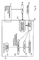
- the Fig. 1 shows an automation system 1 with a press 2 and two of these associated robots 3, 3a.
- the press 2 has a press control 4 and the robots 3, 3a have robot controls 5, 5a.
- the robot 3 leads the press 2 via its gripper 6 to a flat blank sheet 7, which is formed in the press to a molding 7a and gripped by the robot 3a by means of its gripper 6a and removed from the press 2.
- the motion control of the robot is performed by a robot program that contains at least one motion object.
- the synchronous to the press cyclic movements of the two robots 3 and 3a must also be maintained on the moving object.
- the movement object is executed as a function of a control variable of the press control.
- the control variable of the press control can be understood as the angle of an electronic vertical wave, which executes the execution cycle of the individual movement instructions for the robot contained in the movement object synchronously with the press control or its system time.
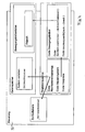
- the Fig. 2 shows the basic structure of an inventively designed robot controller 5, 5a (shown by the example of the robot controller 5).
- the robot controller FIG. 5 comprises, in a known manner, an interpreter or compiler 5.1, by which a fixed set of program and / or manual movement commands of motion planning is interpreted.
- the controller 5 also has an interpolator 5.3, which converts the program and / or manual movement commands into drive signals for a drive interface 5.4.
- Via an access library 5.5 the movement objects contained in the motion planning 5.2 can be read out.
- a file 12 assigned to the motion object is accessed via the access library 5.5 and movement data, system states and peripheral states are read from the file 12 into the interpolator 5.3.
- System and peripheral states can be read from external or internal diagnosis and modification tools 11 in the file 12 of the moving object.
- Data from a sensor driver 5.6 can be read synchronously in real time via the access library 5.5 in addition to the data from the file 12 in the interpolator 5.3.
- the evaluation is performed by calling the appropriate invoice specification in the context of the cyclic execution. It is also possible to use the standard existing compiler or interpreter 5.1 of a robot controller 5 to evaluate given as a string functions.
- the invention further includes the definition of a base class of motion drivers in a definition file.
- This class describes a motion driver for managing a collection of motion objects.
- driver file which also includes a file of the robot library.
- the program source code can be translated into machine interpretable object code which is stored in a file.
- each time the interface is used it is checked whether a driver for motion objects exists in the form of executable object codes. If necessary, this object code is bound to the controller.
- this object code is bound to the controller.
- a memory extension provides a mechanism with which there are a variety of ways of communicating with the motion interface, although the programming language of the controller has only been extended by one instruction.
- commands are conceivable, for example the query of the robot position, of system and / or peripheral states at a specific time and their assignment to variables of the programming language as well as the integration of commands of the motion interface into a graphical user interface.
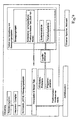
- FIG. 4 schematically illustrates the process of transmitting a driver command:
- the control core and the reloaded driver object is a symbol known in the symbol tables, in which by the reload mechanism, a pointer is entered on the motion driver.
- a command of the programming language then leads to the call of the driver method.
- All operations in a real implementation of the invention use the locking and synchronization mechanisms required for a real-time multitasking environment, preventing, for example, one motion object from being deleted from one task while it is being processed by another task.
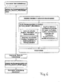
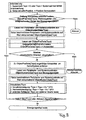
- Cyclic motion, system and / or peripheral states are sent to the motion object between a motion object specific "start of record” command and an "end of record” command sent by either an operator panel or a program, such as this by arrows in the Fig. 5 and in its single flow in the flow chart of Fig. 6 is shown.
- the recording state of the moving object is set to active.
- a reading of current position peripheral and system states is carried out, whereby defined interface functions for reading position system and peripheral states, etc. is accessed.
- the loop stores current position peripheral and system states in the motion object.
- the recording state of the moving object is set to completion, whereupon storage is made.
- a calling mechanism for moving objects is created in a cyclically-preferably in the interpolation cycle of the control-passed part of the control.
- the required commands are preferably processed in the interpreter of the controller, which does not run at a fixed rate.
- the motion object If the motion object is to be used for playback, then it must be ensured that the motion sequence ends with velocity and acceleration 0 for all axes of the robot, otherwise it will be during playback results in a jump that is physically unrealizable.
- Ready-made motion objects can be written to external memories via a memory command for subsequent playback, modification and / or optimization or diagnostics.
- the starting point is an existing motion object in the memory.
- the independent variable that parameterizes the motion object is interpreted as time.
- the same procedure can also be carried out for the case of "king wave" with the kingpin angle as an independent variable.
- the motion object may have been generated via a load instruction or may have been implicitly generated by loading a motion driver over the interface, with the driver contributing approximately a fixed set of motion objects that are read-only accessible.
- a motion object including temporally corresponding system and / or peripheral states is reproduced.
- the starting point is that state-of-the-art robot controls are programmed so that only the target point of the movement is specified, while the current position is used as the starting point. Depending on the current position, different movements then result for a linear command. Of the Movement command for playback is different because full movement is given as a function of time. Execution is only possible if the current position matches the start position of the motion object. Therefore, the starting position of the moving object is first interrogated assuming that the independent quantity is interpreted as time and positioned there with a point-to-point movement.
- a movement command for playback is then, as shown in the flow chart of the Fig. 8 is shown, triggered the execution of the movement described in a movement object.
- system and peripheral states are initialized to the state stored in the motion object at time TSys. This differs from the following cyclic part of the processing, because at the beginning of the motion typically many initialization operations are necessary, while cyclically there are only a few changes of system and peripheral states, such as opening and closing the gripper only a few times, such as ten times within a one-minute cycle, corresponding to 500 to 1000 interpolation cycles.
- the system time is updated, either via an override mechanism as described below or via an external input.
- the end of the motion executions is achieved when either the system time exceeds the duration of the motion object or a kill signal arrives.
- the advantage of this approach is that freely defined motion profiles that were not generated with the help of the manipulator, as well as associated peripheral and / or system states can be processed and executed via an integrated mechanism at runtime of the controller.
- the interface commands are part of the programming language and are not only accessible to the manufacturer of the controller.
- motion objects can reproduce only certain components of the motion system and / or peripheral states (parameterizable), e.g. only the orientation portion of the movement, only certain outputs or the like.
- peripheral states e.g. only the orientation portion of the movement, only certain outputs or the like.
- only system states can be used, and not the actual motion data, in order to optimize the application of adhesive on a fixed path, for example via an analog output.
- the nozzle of a glue gun can be controlled via a speed-proportional analog output, so that uniform application of adhesive is ensured regardless of the speed of movement of the nozzle.
- the analog value or a voltage value, of the speed-proportional analog output separately to treat ie adjust.
- the analog value can be modified at the beginning of the adhesive application ie when the nozzle is opened and at the end of the adhesive application, ie when the nozzle is closed, if the application of adhesive is unfavorable.
- the analog values in the stored file can be changed numerically and the movement object modified in this way can subsequently be executed, so that an improved application of adhesive is achieved.
- robot controls have a so-called override mechanism that allows the execution of motions at a speed other than programmed.
- the override is given as a percentage 0 ⁇ O V ⁇ 100 .
- TSYS : TSYS + Ov / 100 * T_IPO .
- TSYS : TSYS + factor * T IPO .
- Factor Max (F): Speed of movement does not exceed Ov-percent of maximum speed if there is movement from Pos (TSys) to Pos (TSys + Ov / 100 * T_IPO) within T IPO .
- Reverse driving can be implemented by override-dependent reductions in system time, ie O V ⁇ 0 .
- the system time is changed override depending on just this usual behavior of the time scaling or speed capping also for movements that run through the interface.
- This method is possible because communication with the motion interface occurs over system time, unlike sensor drivers, where a correction or position setpoint is fetched and executed at regular intervals regardless of the system time.
- the advantage of this approach according to the invention is that all the mechanisms of a prior art control that internally use the system time, such as reverse, override, emergency stop, reduced speed in test modes, can be used.
- the path in the movement object available accuracy is executed at a small override, as far as a data format is used in the motion object, the movements not differently than in the above example parameterized not only discrete values, such as in the interpolation cycle, but continuous functions of the time parameterized polynomials or splines: If only the discrete values are stored at multiples of 0.5 milliseconds with an IPO cycle of 0.5 milliseconds, the exact course of the desired sine function can not be reconstructed via a motion object - even if instead of linear interpolation Higher order polynomials are used. However, the sine function can be realized in a simplest and memory-saving manner without using a table by a motion object that implements the position query as follows.
- the previous representation used the internal system time as an independent variable, which is used as an argument for the function represented by the motion object, ie, as a "position in the motion object".
- the internal system time of the robot controller is used to scan the motion profiles ignored. Instead, the motion execution is modified via a functional relationship of known quantities of control: eg the system time of an external control is read from an analog input without the position of a mechanical or electronic master shaft for cyclically interrogating a motion profile with option of override change.
- the local press control is autonomous and has its own system time, such as a real time, it is communicated to the robot controls 5, 5a.
- the cyclical movement of the robots 3, 3a is controlled by a moving object which reads in the system time of the press control.
- the moving objects for the robots 3, 3a must have the same duration, namely exactly the cycle duration TP of the press and have a cyclic structure, ie the positions defined by the moving objects at time 0 and TP must match, as well as at least the first and second derivative of the position, ie speed and acceleration.
- the local system time of the press control is transferred via a fieldbus or an analog output to the robot controls 5, 5a.
- the press system time TSysPresse increases from the start of the entire system to 0.
- the robot controls 5, 5a receive a slower system time, which further secures the collision freedom.
- the system time of the press control 4 is stopped, whereby automatically stop the robot 3, 3a, since the moving objects now receive a constant system time from the press control 4. It is also possible to run the press 2 "backwards", for example, to retract after a fault.
- the communication between the units is reduced to cyclic transmission of the system time in one direction. Elaborate exchange of synchronization signals between all controllers involved is eliminated.
- the position of the press control 4 can be interpreted as "angle" Q of an electronic master shaft, which can assume values between 0 ° and 360 °.
- This angle Q is used as an argument to the function represented by the motion object. Since the angle can not leave the range 0 ° ... 360 °, the above-mentioned modulo operation is omitted.
- the motion objects are still considered to represent a cycle with a length of 360 °.
- the position of the moving object is then interrogated via ObjectPos (Q), whereby the angle Q is transmitted cyclically from the press control to the robot control.
- An interpretation is also advantageous when the robot is moved as a whole on a traversing and moving device, such as a rail, on a rotating turntable or on a movable in the plane or in space linear unit to the reachable space during of the business.
- the movement of the robot is fixed and depends on the position of the traversing device.
- the independent size is equated with a position of the robot on the track.
- the position of the track thus corresponds to the position of the press in the above example. This ensures that the robot always performs the movements that are appropriate for the current environment synchronously.
- the robot movements in an entertainment application should be carried out synchronously with image and sound data (film).
- the position of a video or audio tape is interpreted as an independent variable. If the entertainment application has to be stopped due to a technical malfunction during operation, the robot automatically moves back to the movie after restart.
- multiple robots without image and sound data are synchronously controlled with each other, e.g. In the limited space of a leisure park, the robots do not collide in their movement.
Landscapes
- Engineering & Computer Science (AREA)
- General Engineering & Computer Science (AREA)
- Manufacturing & Machinery (AREA)
- Quality & Reliability (AREA)
- Physics & Mathematics (AREA)
- General Physics & Mathematics (AREA)
- Automation & Control Theory (AREA)
- Numerical Control (AREA)
- Manipulator (AREA)
Applications Claiming Priority (1)
| Application Number | Priority Date | Filing Date | Title |
|---|---|---|---|
| DE102008018962.6A DE102008018962B4 (de) | 2008-04-16 | 2008-04-16 | Verfahren zur Steuerung eines Roboters |
Publications (2)
| Publication Number | Publication Date |
|---|---|
| EP2110727A2 true EP2110727A2 (fr) | 2009-10-21 |
| EP2110727A3 EP2110727A3 (fr) | 2011-01-12 |
Family
ID=40888073
Family Applications (1)
| Application Number | Title | Priority Date | Filing Date |
|---|---|---|---|
| EP09004511A Withdrawn EP2110727A3 (fr) | 2008-04-16 | 2009-03-28 | Procédé destiné à la commande d'un robot |
Country Status (2)
| Country | Link |
|---|---|
| EP (1) | EP2110727A3 (fr) |
| DE (1) | DE102008018962B4 (fr) |
Cited By (3)
| Publication number | Priority date | Publication date | Assignee | Title |
|---|---|---|---|---|
| US9904277B2 (en) | 2014-02-21 | 2018-02-27 | Fanuc Corporation | Numerical controller configured for operation based on tabular data |
| CN113316502A (zh) * | 2019-02-05 | 2021-08-27 | 富兰卡爱米卡股份有限公司 | 两个机器人臂的彼此对准 |
| CN114096383A (zh) * | 2019-02-11 | 2022-02-25 | 海别得公司 | 机器人系统中的运动分配 |
Families Citing this family (4)
| Publication number | Priority date | Publication date | Assignee | Title |
|---|---|---|---|---|
| DE102017210947B4 (de) * | 2017-06-28 | 2019-08-01 | Kuka Deutschland Gmbh | Feedback Robotermechanik |
| DE102017008748A1 (de) * | 2017-09-19 | 2019-03-21 | Innolite Gmbh | Software-Baustein, Präzisionsmaschine, Verfahren und Bauteil |
| JP7415345B2 (ja) * | 2019-07-03 | 2024-01-17 | オムロン株式会社 | 制御システム、サポート装置および設定プログラム |
| DE102021107887A1 (de) | 2021-03-29 | 2022-09-29 | Broetje-Automation Gmbh | Verfahren zur Bearbeitung eines Fahrzeugstrukturbauteils |
Citations (1)
| Publication number | Priority date | Publication date | Assignee | Title |
|---|---|---|---|---|
| DE10125245A1 (de) | 2000-09-11 | 2002-04-18 | Michael Borgmann | Brühkopf für eine Espressomaschine |
Family Cites Families (9)
| Publication number | Priority date | Publication date | Assignee | Title |
|---|---|---|---|---|
| DE19751955A1 (de) * | 1997-11-24 | 1999-06-02 | Biotechnolog Forschung Gmbh | Virtueller Roboter |
| US6442442B1 (en) * | 1999-09-30 | 2002-08-27 | Rockwell Automation Technologies, Inc. | System level data flow programming interface for a multi-axis industrial control system |
| JP2001212781A (ja) * | 2000-02-02 | 2001-08-07 | Aida Eng Ltd | ロボットの同期制御装置 |
| DE10147421A1 (de) * | 2001-03-16 | 2002-09-26 | Siemens Ag | Anwendungen eines schaltbaren Datennetzes für Echtzeit- und Nichtechtzeitkommunikation |
| JP3665008B2 (ja) * | 2001-10-25 | 2005-06-29 | ファナック株式会社 | 同期制御方法及び同期制御装置 |
| DE10343809B4 (de) * | 2002-09-27 | 2018-03-15 | Siemens Aktiengesellschaft | Verfahren und Vorrichtung zur numerischen Steuerung |
| JP2004246498A (ja) * | 2003-02-12 | 2004-09-02 | Fanuc Ltd | 位置制御装置 |
| US20070142966A1 (en) * | 2005-12-20 | 2007-06-21 | Khalid Mirza | Process for moving a robot |
| DE102007006422B4 (de) * | 2007-02-05 | 2024-06-06 | Robert Bosch Gmbh | Verfahren zum Betreiben von Maschinen mit anpassbaren Bewegungsprofilen |
-
2008
- 2008-04-16 DE DE102008018962.6A patent/DE102008018962B4/de active Active
-
2009
- 2009-03-28 EP EP09004511A patent/EP2110727A3/fr not_active Withdrawn
Patent Citations (1)
| Publication number | Priority date | Publication date | Assignee | Title |
|---|---|---|---|---|
| DE10125245A1 (de) | 2000-09-11 | 2002-04-18 | Michael Borgmann | Brühkopf für eine Espressomaschine |
Cited By (6)
| Publication number | Priority date | Publication date | Assignee | Title |
|---|---|---|---|---|
| US9904277B2 (en) | 2014-02-21 | 2018-02-27 | Fanuc Corporation | Numerical controller configured for operation based on tabular data |
| DE102015001887B4 (de) * | 2014-02-21 | 2019-11-07 | Fanuc Corporation | Numerische Steuervorrichtung, die für einen Betrieb auf der Grundlage von Tabellendaten konfiguriert ist |
| CN113316502A (zh) * | 2019-02-05 | 2021-08-27 | 富兰卡爱米卡股份有限公司 | 两个机器人臂的彼此对准 |
| CN113316502B (zh) * | 2019-02-05 | 2024-05-28 | 富兰卡爱米卡股份有限公司 | 两个机器人臂的彼此对准 |
| CN114096383A (zh) * | 2019-02-11 | 2022-02-25 | 海别得公司 | 机器人系统中的运动分配 |
| CN114096383B (zh) * | 2019-02-11 | 2024-05-14 | 海别得公司 | 机器人系统中的运动分配 |
Also Published As
| Publication number | Publication date |
|---|---|
| DE102008018962B4 (de) | 2015-08-20 |
| DE102008018962A1 (de) | 2009-10-22 |
| EP2110727A3 (fr) | 2011-01-12 |
Similar Documents
| Publication | Publication Date | Title |
|---|---|---|
| EP1131686B1 (fr) | Procede de commande de processus techniques | |
| DE102019001948B4 (de) | Steuerung und maschinelle Lernvorrichtung | |
| DE102008018962B4 (de) | Verfahren zur Steuerung eines Roboters | |
| DE112008003963B4 (de) | System und Verfahren zur Off-line-Programmierung eines Industrieroboters | |
| DE102009057923B4 (de) | Simulationsvorrichtung | |
| DE10352815B4 (de) | Simulationsverfahren für eine Bearbeitung eines Werkstücks durch eine Werkzeugmaschine und korrespondierender Rechner | |
| EP2486460B1 (fr) | Procédé pour commander et faire fonctionner une cellule de production et un dispositif de commande | |
| DE102017004366B4 (de) | Numerische Steuervorrichtung | |
| EP1901149A2 (fr) | Procédé et dispositif destinés à la simulation de l'usinage d'une pièce sur une machine-outil | |
| DE19639424A1 (de) | Entwurfsverfahren für die Anlagentechnik und rechnergestütztes Projektierungssystem zur Verwendung bei diesem Verfahren | |
| DE10061933A1 (de) | Verlustbewegungskorrektursystem und Verlustbewegungskorrekturverfahren für ein numerisch gesteuertes Maschinenwerkzeug | |
| DE69837778T2 (de) | Steuerungsvorrichtung für eine produktionsanlage | |
| DE102009003003A1 (de) | Numerische Steuerung mit der Funktion einer Koordinatentransformation der Werkzeugphase | |
| DE102023207127A1 (de) | Parametrierung eines digitalen Zwillings und/oder eines Automatisierungs-systems | |
| DE112021006982T5 (de) | Simulationsvorrichtung, Werkzeugmaschinensystem, Simulationsverfahren und Bearbeitungsverfahren | |
| DE10231675A1 (de) | Simulationssystem für die Maschinensimulation und Datenausgabe von Steuerdaten für ein Automatisierungssystem | |
| WO2006089451A1 (fr) | Procede pour la commande et l'utilisation d'une cellule de production et dispositif de commande | |
| DE102009026412A1 (de) | Numerische Steuervorrichtung mit der Funktion zur Durchführung einer zyklischen Hochgeschwindigkeitsbearbeitung | |
| DE102018007107A1 (de) | Steuereinrichtung und maschinenlerneinrichtung | |
| EP1217476A2 (fr) | Appareil et méthode pour la mise en service et le diagnostic de systèmes de commande | |
| DE102017004822A1 (de) | Numerische Steuerung mit einer Programmkorrektur-Assistenzfunktion für eine Alarmlösung | |
| DE3883682T2 (de) | Verfahren und Gerät zum Erzeugen und Verwenden gemeinsamer Daten von Robotern. | |
| DE112008003870T5 (de) | Verfahren und System zum Steuern eines Industrieroboters in Übereinstimmung mit einem Bewegungssteuerungs-Parametersatz | |
| DE102008023873A1 (de) | Verfahren zum Betrieb eines Antriebssystems | |
| EP1944664B1 (fr) | Procédé de diagnostic d'erreurs dans un automate programmable |
Legal Events
| Date | Code | Title | Description |
|---|---|---|---|
| PUAI | Public reference made under article 153(3) epc to a published international application that has entered the european phase |
Free format text: ORIGINAL CODE: 0009012 |
|
| AK | Designated contracting states |
Kind code of ref document: A2 Designated state(s): AT BE BG CH CY CZ DE DK EE ES FI FR GB GR HR HU IE IS IT LI LT LU LV MC MK MT NL NO PL PT RO SE SI SK TR |
|
| AX | Request for extension of the european patent |
Extension state: AL BA RS |
|
| RIN1 | Information on inventor provided before grant (corrected) |
Inventor name: WEISS, MARTIN Inventor name: MUELLER-SOMMER, MARTIN |
|
| PUAL | Search report despatched |
Free format text: ORIGINAL CODE: 0009013 |
|
| AK | Designated contracting states |
Kind code of ref document: A3 Designated state(s): AT BE BG CH CY CZ DE DK EE ES FI FR GB GR HR HU IE IS IT LI LT LU LV MC MK MT NL NO PL PT RO SE SI SK TR |
|
| AX | Request for extension of the european patent |
Extension state: AL BA RS |
|
| RIC1 | Information provided on ipc code assigned before grant |
Ipc: B25J 9/16 20060101ALI20101206BHEP Ipc: G05B 19/42 20060101AFI20090730BHEP |
|
| 17P | Request for examination filed |
Effective date: 20110712 |
|
| 17Q | First examination report despatched |
Effective date: 20110811 |
|
| AKX | Designation fees paid |
Designated state(s): DE FR IT |
|
| STAA | Information on the status of an ep patent application or granted ep patent |
Free format text: STATUS: THE APPLICATION HAS BEEN WITHDRAWN |
|
| 18W | Application withdrawn |
Effective date: 20120911 |
|
| P01 | Opt-out of the competence of the unified patent court (upc) registered |
Effective date: 20230528 |