EP2110835A1 - Préparation pour la fermeture d'indicateur pour disjoncteurs - Google Patents
Préparation pour la fermeture d'indicateur pour disjoncteurs Download PDFInfo
- Publication number
- EP2110835A1 EP2110835A1 EP09157296A EP09157296A EP2110835A1 EP 2110835 A1 EP2110835 A1 EP 2110835A1 EP 09157296 A EP09157296 A EP 09157296A EP 09157296 A EP09157296 A EP 09157296A EP 2110835 A1 EP2110835 A1 EP 2110835A1
- Authority
- EP
- European Patent Office
- Prior art keywords
- ready
- close
- circuit breaker
- trip
- coupled
- Prior art date
- Legal status (The legal status is an assumption and is not a legal conclusion. Google has not performed a legal analysis and makes no representation as to the accuracy of the status listed.)
- Granted
Links
Images





Classifications
-
- H—ELECTRICITY
- H01—ELECTRIC ELEMENTS
- H01H—ELECTRIC SWITCHES; RELAYS; SELECTORS; EMERGENCY PROTECTIVE DEVICES
- H01H71/00—Details of the protective switches or relays covered by groups H01H73/00 - H01H83/00
- H01H71/04—Means for indicating condition of the switching device
-
- H—ELECTRICITY
- H01—ELECTRIC ELEMENTS
- H01H—ELECTRIC SWITCHES; RELAYS; SELECTORS; EMERGENCY PROTECTIVE DEVICES
- H01H71/00—Details of the protective switches or relays covered by groups H01H73/00 - H01H83/00
- H01H71/10—Operating or release mechanisms
- H01H71/50—Manual reset mechanisms which may be also used for manual release
- H01H71/501—Means for breaking welded contacts; Indicating contact welding or other malfunction of the circuit breaker
-
- H—ELECTRICITY
- H02—GENERATION; CONVERSION OR DISTRIBUTION OF ELECTRIC POWER
- H02B—BOARDS, SUBSTATIONS OR SWITCHING ARRANGEMENTS FOR THE SUPPLY OR DISTRIBUTION OF ELECTRIC POWER
- H02B11/00—Switchgear having carriage withdrawable for isolation
- H02B11/12—Switchgear having carriage withdrawable for isolation with isolation by horizontal withdrawal
- H02B11/127—Withdrawal mechanism
- H02B11/133—Withdrawal mechanism with interlock
-
- H—ELECTRICITY
- H01—ELECTRIC ELEMENTS
- H01H—ELECTRIC SWITCHES; RELAYS; SELECTORS; EMERGENCY PROTECTIVE DEVICES
- H01H71/00—Details of the protective switches or relays covered by groups H01H73/00 - H01H83/00
- H01H71/04—Means for indicating condition of the switching device
- H01H2071/042—Means for indicating condition of the switching device with different indications for different conditions, e.g. contact position, overload, short circuit or earth leakage
Definitions
- the subject invention relates to circuit breakers, and more particularly the subject invention relates to an indicator that indicates a visual and electrical indication on the status of "Readiness to close” (RTC) for circuit breakers.
- RTC Readiness to close
- a circuit breaker is an automatically-operated electrical switch designed to protect an electrical circuit from damage caused by overload or short circuit. Unlike a fuse, which operates once and then has to be replaced, a circuit breaker can be reset (either manually or automatically) to resume normal operation. A switch mechanism of the breaker can then be thrown to open and close contacts to which the load is connected.
- a circuit breaker may be in different states, in particular a closed state with closing springs energized, a closed state with closing spring not energized, an open state with closing springs energized, an open state with closing spring not energized, an open state with any interlock applied condition, and an open state with any interlocks not applied.
- the closing spring should be energized
- the breaker contacts should be in open state
- interlock should not be applied.
- FIG. 1 For exemplary embodiments, include a circuit breaker system, including a circuit breaker having circuit breaker contacts and a closing spring, the closing spring operatively coupled to a charging cam assembly, a lay shaft coupled to the circuit breaker contacts, a lay shaft cam profile coupled to the lay shaft, a trip free plate coupled to lay shaft cam profile, a trip paddle coupled to the trip free plate, the trip paddle being coupled to a trip shaft and a ready to close indicator coupled to the trip free plate and a charging cam assembly.
- a circuit breaker system including a circuit breaker having circuit breaker contacts and a closing spring, the closing spring operatively coupled to a charging cam assembly, a lay shaft coupled to the circuit breaker contacts, a lay shaft cam profile coupled to the lay shaft, a trip free plate coupled to lay shaft cam profile, a trip paddle coupled to the trip free plate, the trip paddle being coupled to a trip shaft and a ready to close indicator coupled to the trip free plate and a charging cam assembly.
- FIG. 1A illustrates a front perspective view of a circuit breaker assembly in accordance with exemplary embodiments
- FIG. 1B illustrates a front perspective view of a circuit breaker assembly in accordance with exemplary embodiments
- FIG. 1C illustrates an perspective front view of an exemplary circuit breaker
- FIG. 1D illustrates an perspective front view of an exemplary circuit breaker
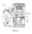
- FIG. IE illustrates a side view of a circuit breaker assembly in accordance with exemplary embodiments
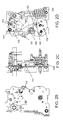
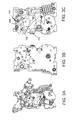
- FIGS. 2A-2D illustrate multiple views of a circuit breaker in a condition of breaker charged and contacts open condition in accordance with exemplary embodiments
- FIGS. 3A-3C illustrate multiple view of a circuit breaker in a condition of breaker charged, contacts open condition and trip coil activated in accordance with exemplary embodiments
- FIGS. 4A-C illustrate multiple views of a circuit breaker in a condition of breaker charged and contacts closed condition in accordance with exemplary embodiments
- FIGS. 5A-5C illustrate multiple views of a circuit breaker in a condition of breaker discharged and contacts open condition in accordance with exemplary embodiments
- FIG. 5D illustrates a side view of an exemplary closing cam plate
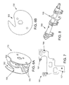
- FIG. 6A illustrates a side perspective view of a charging cam assembly in accordance with exemplary embodiments
- FIG. 6B illustrates a side view of a ready to close cam in accordance with exemplary embodiments
- FIG. 7 illustrates a side view of a trip free plate in accordance with exemplary embodiments.
- FIG. 8 illustrates a perspective view of a lay shaft having a lay shaft cam profile in accordance with exemplary embodiments.
- Exemplary embodiments provide indication of "ready to close " for a circuit breaker in response to all of the following conditions of the circuit breaker being satisfied: 1) the circuit breaker main spring is charged; 2) the shunt coil is not energized; 3) the UV coil if installed is energized; 4) the circuit breaker is not locked in OFF position by any of the provided locking/ interlock means; 5) the circuit breaker is in OFF position; and 6) the mechanical lockout in the protection unit assembly is reset. If any one or more of the above conditions are not satisfied the indicator as described herein does not indicate "ready to close".
- the indication can be a visible flag showing "Readiness to close status" or an electrical signal.
- the interlock application may be either through energizing shunt coils, not energizing under voltage coils, application of padlock/key lock.
- FIG. 1 illustrates a perspective view of a circuit breaker assembly 100 in accordance with exemplary embodiments.
- the assembly 100 includes a breaker housing 105, a circuit breaker 150 disposed within the housing 105 and a lay shaft 163 disposed within the housing 105 and coupled to the circuit breaker 150.
- the assembly 100 further includes a trip unit 119 shown assembled thereto.
- the assembly 100 is configured to allow current to flow through a circuit (not shown) in response to being in a closed configuration and to prevent current from flowing through the circuit in response to the assembly 100 being in an open configuration.
- the circuit breaker 150 further includes a "readiness to close" (RTC) indicator 151 coupled to a trip free plate 155.
- RTC readiness to close
- the circuit breaker 150 further includes a charging cam assembly 170 having a RTC cam 156 coupled to the RTC indicator 151 as further described herein.
- the RTC indicator 151 can indicate a "ready to close" condition of the circuit breaker when the above-discussed criteria has been met as now described in accordance with exemplary embodiments.
- FIG. 1B illustrates a front perspective view of a circuit breaker assembly in accordance with exemplary embodiments.
- the circuit breaker assembly 100 includes a front cover 101 in which the RTC indicator 151 can be viewed through an RTC indicator opening 102.
- FIGS. 1C-1D illustrate perspective front views of the exemplary circuit breaker 150.
- the circuit breaker 150 includes an opening coil interface 111,154,114, which can be referred to as a trip paddle, collectively, which is coupled to a trip shaft.
- the opening coil can be either a shunt coil or a under voltage coil.
- a shunt coil is implemented for opening the circuit breaker 150 and an under voltage coil is implemented for checking the breaker voltage, and if the voltage is not with in the range then the under voltage coil opens the circuit breaker 150.
- An interlock can also be applied via the above-described coils. For applying an interlock, the shunt coil has to be powered.
- the shunt coil plunger pushes the trip paddle down and keeps the circuit breaker in a not ready close condition.
- the under voltage coil has to be energized for keeping the circuit breaker in a ready to close condition.
- the under voltage coil is not energized. As such, the under voltage coil plunger pushes the trip paddle and keeps the circuit breaker in a not ready to close condition.
- FIG. IE illustrates a side view of a circuit breaker assembly 100 in accordance with exemplary embodiments.
- the circuit breaker 150 is operatively coupled to a moving finger 132 via a coupler 124 and lay shaft 163 (described further herein).
- the moving finger is held in place by a contact spring 126.
- a contact tip 134 disposed on the moving finger 132 is configured to engage a contact tip 142 disposed on a terminal 144.
- FIGS. 2A-2D illustrate multiple views of the circuit breaker 150 in a condition of breaker charged and contacts open (with the main spring 162 charged and compressed) condition in accordance with exemplary embodiments. Furthermore, the interlock, as discussed above, is not applied.
- the breaker charged condition includes a main breaker spring 162 being charged.
- the circuit breaker includes the RTC indicator 151 coupled to the trip free plate 155 and to the RTC cam 156.
- the RTC indicator 151 includes an RTC indicator arm 180 and cam pin 181 configured to engage a cam groove 182 disposed on the RTC cam 156.
- the trip free plate 155 includes a trip free rear pin 160 and a trip free front pin 161, as further illustrated in FIG. 7 .
- the RTC indicator 151 is in a ready to close indicator active condition.
- the RTC indicator 151 is biased downward via a biasing member (not shown, e.g., a spring) and the cam pin 181 engages (i.e., drops into) the RTC cam groove 182.
- the RTC indicator 151 displays the status of "ready to close”.
- the RTC indicator is coupled to a micro-switch 152 (see FIG. 2B ).
- the RTC indicator 151 also activates the micro switch 152, which, in turn is implemented as an electrical indication of "ready to close".
- the micro switch 152 N0/NC contacts can be implemented as an electrical indication.
- the micro switch 152 contacts are closed and vice versa for an RTC inactive condition.
- FIGS. 3A-3C illustrates multiple views of the circuit breaker 150 in a condition of breaker charged, contacts open (with the main spring 162 charged and compressed) condition and trip coil activated in accordance with exemplary embodiments.
- the RTC indictor is in a ready to close indicator inactive condition.
- the trip paddle 154 is pushed down as indicted by directional arrow 158 as an indictor that the trip coil (not shown) has been activated.
- the interlock is applied as via the trip coil.
- the trip paddle 154 engages and pushes the trip free plate 155 via trip free front pin 161.
- the trip free cam profile 157 in response to the resultant movement of the trip free plate 155, the trip free cam profile 157 (see also FIG. 7 ) also moves, thereby engaging and rotating the RTC indicator 151.
- the resultant movement of the RTC indicator 151 hides the "ready to close” insignia indication from the user.
- the movement of the RTC indicator 151 also prevents activation of the micro-switch 152.
- the RTC indicator 151 is biased downward via a biasing member (not shown, e.g., a spring) and the cam pin 181 dis-engages (i.e., is raised from) the RTC cam groove 182.
- FIGS. 4A-4C illustrate multiple views of a circuit breaker in a condition of breaker charged and contacts closed (with the main spring 162 charged and compressed) condition in accordance with exemplary embodiments.
- the lay-shaft cam profile 159 of the lay shaft 163 engages and pushes the trip free plate 155) via the trip free rear pin 160.
- the trip free cam profile 157 rotates the RTC indicator 151 and prevents RTC indicator 151 from displaying the "ready to close" insignia and which, in turn, prevents the activation of the micro-switch 152 as described above.
- the cam pin 181 dis-engages (i.e., is raised from) the RTC cam groove 182.
- the RTC indictor is in a ready to fall condition in which the cam pin 181 is ready to fall into the RTC cam groove 182.
- the RTC indicator is blocked to the fall condition by the trip free cam profile 157 in which the cam pin 181 is blocked to fall in to the groove 182 by the trip free cam profile 157.
- FIGS. 5A-5C illustrate multiple views of a circuit breaker in a condition of breaker discharged and contacts open (with the main spring 162 dis - charged and extended) condition in accordance with exemplary embodiments.
- the RTC indictor is in a ready to close indicator in-active condition, and the interlock is not applied.
- the RTC cam is rotated thereby preventing the cam pin 181 from falling into the cam groove 182.
- the RTC cam 156 prevents the RTC indicator 151 from showing the "ready to close” insignia and which, in turn, prevents the activation of micro-switch 152.
- FIG. 5C illustrates the cam pin 181 resting on the RTC cam 156 outside the RTC cam groove 182.
- FIG. 5A further illustrates that the charging cam assembly 170 includes a charging cam 183 and a closing cam plate 190 coupled to the charging cam assembly 170.
- FIG. 5D illustrates a side view of an exemplary closing cam plate 190 including a closing cam plate bushing 191 a closing cam rivet pin 192 and a closing cam roller 193.
- a charging operation of the charging cam assembly 170 includes rotating the cam shaft 164 as illustrated by arrow A counterclockwise by a handle or motor (not shown).
- a cam profile 184 interacts with the closing cam roller 193 when cam shaft 164 is rotated, which, in turn, rotates the closing cam plate 190 in a clockwise direction there by compressing the spring 162.
Landscapes
- Engineering & Computer Science (AREA)
- Power Engineering (AREA)
- Driving Mechanisms And Operating Circuits Of Arc-Extinguishing High-Tension Switches (AREA)
- Breakers (AREA)
- Switch Cases, Indication, And Locking (AREA)
Applications Claiming Priority (1)
| Application Number | Priority Date | Filing Date | Title |
|---|---|---|---|
| US12/103,056 US7906740B2 (en) | 2008-04-15 | 2008-04-15 | Readiness for closing indicator for circuit breakers |
Publications (2)
| Publication Number | Publication Date |
|---|---|
| EP2110835A1 true EP2110835A1 (fr) | 2009-10-21 |
| EP2110835B1 EP2110835B1 (fr) | 2014-02-26 |
Family
ID=40908390
Family Applications (1)
| Application Number | Title | Priority Date | Filing Date |
|---|---|---|---|
| EP09157296.6A Active EP2110835B1 (fr) | 2008-04-15 | 2009-04-03 | Préparation pour la fermeture d'indicateur pour disjoncteurs |
Country Status (5)
| Country | Link |
|---|---|
| US (1) | US7906740B2 (fr) |
| EP (1) | EP2110835B1 (fr) |
| JP (1) | JP2009259820A (fr) |
| KR (1) | KR101070133B1 (fr) |
| CN (1) | CN101562096B (fr) |
Cited By (2)
| Publication number | Priority date | Publication date | Assignee | Title |
|---|---|---|---|---|
| WO2011107858A1 (fr) * | 2010-03-04 | 2011-09-09 | Eaton Corporation | Appareil de commutation électrique et ensemble d'indication d'état pour celui-ci |
| WO2013102726A1 (fr) * | 2012-01-06 | 2013-07-11 | Schneider Electric Industries Sas | Disjoncteur électrique de puissance à accumulateur d'énergie dispositif de signalisation perfectionné de l'état de fonctionnement |
Families Citing this family (8)
| Publication number | Priority date | Publication date | Assignee | Title |
|---|---|---|---|---|
| EP2428973A1 (fr) * | 2010-09-09 | 2012-03-14 | Eaton Industries GmbH | Dispositif indicateur pour disjoncteur |
| US8319133B2 (en) * | 2010-11-02 | 2012-11-27 | Eaton Corporation | Electrical switching apparatus and charging assembly therefor |
| CN106057514B (zh) * | 2016-07-25 | 2018-05-15 | 中能建江苏能源科技有限公司 | 一种手动三工位操作机构 |
| KR101869724B1 (ko) * | 2017-01-05 | 2018-06-21 | 엘에스산전 주식회사 | 회로차단기의 전자 트립 장치 |
| KR102299858B1 (ko) * | 2017-03-15 | 2021-09-08 | 엘에스일렉트릭 (주) | 회로차단기의 전자 트립 장치 |
| US10468219B2 (en) * | 2017-09-07 | 2019-11-05 | Carling Technologies, Inc. | Circuit interrupter with status indication |
| WO2023038556A1 (fr) * | 2021-09-07 | 2023-03-16 | Alfanar Company | Mécanisme à deux leviers multifonction amélioré et simplifié, et disjoncteur miniature amélioré |
| US20250391625A1 (en) * | 2023-05-15 | 2025-12-25 | Shanghai CHINT Low Voltage Electrical Technology Co., Ltd. | Operating mechanism for circuit breaker and circuit breaker |
Citations (2)
| Publication number | Priority date | Publication date | Assignee | Title |
|---|---|---|---|---|
| US6080947A (en) * | 1998-05-07 | 2000-06-27 | Eaton Corporation | Electrical switching apparatus with operating condition indicators mounted in face plate |
| EP2015337A2 (fr) * | 2007-07-12 | 2009-01-14 | LS Industrial Systems Co., Ltd | Appareil d'indication de l'état de fonctionnement de fermeture pour un disjoncteur à air et disjoncteur à air l'utilisant |
Family Cites Families (12)
| Publication number | Priority date | Publication date | Assignee | Title |
|---|---|---|---|---|
| US4146765A (en) * | 1976-10-22 | 1979-03-27 | Gould Inc. | Circuit breaker closing mechanism |
| JPS55108124A (en) * | 1979-02-13 | 1980-08-19 | Tokyo Shibaura Electric Co | Device for operating circuit breaker |
| JPS55108118A (en) * | 1979-02-13 | 1980-08-19 | Tokyo Shibaura Electric Co | Motorrdriven spring operating device for circuit breaker |
| US4491709A (en) * | 1983-05-09 | 1985-01-01 | Square D Company | Motor and blade control for high amperage molded case circuit breakers |
| US5408208A (en) * | 1992-10-22 | 1995-04-18 | Siemens Energy & Automation, Inc. | Electrically tripped mechanism for knife blade switches |
| DE4333828C1 (de) * | 1993-09-30 | 1995-03-09 | Siemens Ag | Einrichtung zur Steuerung der Einschaltung eines Leistungsschalters |
| US5673786A (en) * | 1996-04-04 | 1997-10-07 | General Electric Company | Circuit breaker bell alarm reset mechanism |
| US6072136A (en) * | 1998-05-07 | 2000-06-06 | Eaton Corporation | Electrical switching apparatus with modular operating mechanism for mounting and controlling large compression close spring |
| FR2785444B1 (fr) * | 1998-10-30 | 2000-12-15 | Schneider Electric Ind Sa | Appareillage de coupure comportant un organe mecanique de visualisation a trois positions |
| DE19957391C1 (de) * | 1999-11-24 | 2001-03-29 | Siemens Ag | Einrichtung zur Steuerung der Einschaltung eines Leistungsschalters |
| US6803535B1 (en) * | 2004-02-19 | 2004-10-12 | Eaton Corporation | Circuit breaker with a visual indication of a trip |
| KR100876408B1 (ko) | 2007-07-12 | 2008-12-31 | 엘에스산전 주식회사 | 기계적 트립 표시 기구를 갖는 기중 차단기 |
-
2008
- 2008-04-15 US US12/103,056 patent/US7906740B2/en active Active
-
2009
- 2009-04-03 EP EP09157296.6A patent/EP2110835B1/fr active Active
- 2009-04-10 JP JP2009096157A patent/JP2009259820A/ja not_active Ceased
- 2009-04-14 KR KR1020090032193A patent/KR101070133B1/ko not_active Expired - Fee Related
- 2009-04-15 CN CN200910135189.4A patent/CN101562096B/zh active Active
Patent Citations (2)
| Publication number | Priority date | Publication date | Assignee | Title |
|---|---|---|---|---|
| US6080947A (en) * | 1998-05-07 | 2000-06-27 | Eaton Corporation | Electrical switching apparatus with operating condition indicators mounted in face plate |
| EP2015337A2 (fr) * | 2007-07-12 | 2009-01-14 | LS Industrial Systems Co., Ltd | Appareil d'indication de l'état de fonctionnement de fermeture pour un disjoncteur à air et disjoncteur à air l'utilisant |
Cited By (6)
| Publication number | Priority date | Publication date | Assignee | Title |
|---|---|---|---|---|
| WO2011107858A1 (fr) * | 2010-03-04 | 2011-09-09 | Eaton Corporation | Appareil de commutation électrique et ensemble d'indication d'état pour celui-ci |
| WO2013102726A1 (fr) * | 2012-01-06 | 2013-07-11 | Schneider Electric Industries Sas | Disjoncteur électrique de puissance à accumulateur d'énergie dispositif de signalisation perfectionné de l'état de fonctionnement |
| FR2985600A1 (fr) * | 2012-01-06 | 2013-07-12 | Schneider Electric Ind Sas | Disjoncteur electrique de puissance a accumulateur d'energie et a dispositif de signalisation perfectionne de l'etat de fonctionnement |
| CN104040660A (zh) * | 2012-01-06 | 2014-09-10 | 施耐德电器工业公司 | 具有电池和改进的操作状态的指示装置的电力断路器 |
| US9373457B2 (en) | 2012-01-06 | 2016-06-21 | Schneider Electric Industries Sas | Circuit breaker indicating cam having a profile which reduces transmission of mechanical shocks to the auxiliary release |
| CN104040660B (zh) * | 2012-01-06 | 2016-09-28 | 施耐德电器工业公司 | 具有电池和改进的操作状态的指示装置的电力断路器 |
Also Published As
| Publication number | Publication date |
|---|---|
| KR20090109491A (ko) | 2009-10-20 |
| US7906740B2 (en) | 2011-03-15 |
| US20090256660A1 (en) | 2009-10-15 |
| KR101070133B1 (ko) | 2011-10-05 |
| CN101562096A (zh) | 2009-10-21 |
| JP2009259820A (ja) | 2009-11-05 |
| EP2110835B1 (fr) | 2014-02-26 |
| CN101562096B (zh) | 2014-11-12 |
Similar Documents
| Publication | Publication Date | Title |
|---|---|---|
| EP2110835B1 (fr) | Préparation pour la fermeture d'indicateur pour disjoncteurs | |
| AU2006320816B2 (en) | Fault interrupting and reclosing device | |
| DE19819242B4 (de) | Thermomagnetischer Leistungsschalter | |
| CN102842444B (zh) | 开关装置 | |
| US9928977B2 (en) | Electrical switching apparatus, and operating handle assembly and trip cam therefor | |
| EP2980827A1 (fr) | Panneau pour interverrouillage de rétention positive de disjoncteur | |
| CN102842445A (zh) | 开关装置以及相关的电力分配系统 | |
| KR101904879B1 (ko) | 기중 차단기의 전자 트립장치 | |
| CN109659203A (zh) | 一种小型断路器异常保护装置及小型断路器 | |
| US7583170B2 (en) | Switching device with switch latch | |
| US8624145B2 (en) | Indicator device of a circuit breaker | |
| US6433290B1 (en) | Trip indicator including latch for a circuit breaker | |
| CN114005710A (zh) | 断路器的漏电故障指示机构及断路器 | |
| EP0949647A2 (fr) | Indicateur de déclenchement et ensemble interrupteur de signalisation | |
| KR100978274B1 (ko) | 배선용 차단기 | |
| EP3319102B1 (fr) | Dispositif d'indication de commutation électrique | |
| EP2610886B1 (fr) | Dispositif de déclenchement de tension de pénurie de disjoncteur à boîtier moulé | |
| EP3693985B1 (fr) | Actionneur pour un disjoncteur moyenne tension | |
| JP4867644B2 (ja) | 回路遮断器の外部操作ハンドル装置 | |
| US8809711B2 (en) | Electrical contact position indicator apparatus, systems and methods of operation | |
| CN110050320B (zh) | 保护开关 | |
| KR20210123883A (ko) | 누전 차단기 | |
| CN110940913A (zh) | 用于断路器的短路故障指示及机械测试的机构 | |
| US20150179381A1 (en) | Lever arm for a shunt trip device |
Legal Events
| Date | Code | Title | Description |
|---|---|---|---|
| PUAI | Public reference made under article 153(3) epc to a published international application that has entered the european phase |
Free format text: ORIGINAL CODE: 0009012 |
|
| AK | Designated contracting states |
Kind code of ref document: A1 Designated state(s): AT BE BG CH CY CZ DE DK EE ES FI FR GB GR HR HU IE IS IT LI LT LU LV MC MK MT NL NO PL PT RO SE SI SK TR |
|
| 17P | Request for examination filed |
Effective date: 20100421 |
|
| 17Q | First examination report despatched |
Effective date: 20100601 |
|
| GRAP | Despatch of communication of intention to grant a patent |
Free format text: ORIGINAL CODE: EPIDOSNIGR1 |
|
| INTG | Intention to grant announced |
Effective date: 20130906 |
|
| GRAS | Grant fee paid |
Free format text: ORIGINAL CODE: EPIDOSNIGR3 |
|
| GRAA | (expected) grant |
Free format text: ORIGINAL CODE: 0009210 |
|
| AK | Designated contracting states |
Kind code of ref document: B1 Designated state(s): AT BE BG CH CY CZ DE DK EE ES FI FR GB GR HR HU IE IS IT LI LT LU LV MC MK MT NL NO PL PT RO SE SI SK TR |
|
| REG | Reference to a national code |
Ref country code: GB Ref legal event code: FG4D |
|
| REG | Reference to a national code |
Ref country code: CH Ref legal event code: EP |
|
| REG | Reference to a national code |
Ref country code: AT Ref legal event code: REF Ref document number: 654018 Country of ref document: AT Kind code of ref document: T Effective date: 20140315 |
|
| REG | Reference to a national code |
Ref country code: IE Ref legal event code: FG4D |
|
| REG | Reference to a national code |
Ref country code: DE Ref legal event code: R096 Ref document number: 602009021965 Country of ref document: DE Effective date: 20140410 |
|
| REG | Reference to a national code |
Ref country code: NL Ref legal event code: VDEP Effective date: 20140226 |
|
| REG | Reference to a national code |
Ref country code: AT Ref legal event code: MK05 Ref document number: 654018 Country of ref document: AT Kind code of ref document: T Effective date: 20140226 |
|
| REG | Reference to a national code |
Ref country code: LT Ref legal event code: MG4D |
|
| PG25 | Lapsed in a contracting state [announced via postgrant information from national office to epo] |
Ref country code: LT Free format text: LAPSE BECAUSE OF FAILURE TO SUBMIT A TRANSLATION OF THE DESCRIPTION OR TO PAY THE FEE WITHIN THE PRESCRIBED TIME-LIMIT Effective date: 20140226 Ref country code: IS Free format text: LAPSE BECAUSE OF FAILURE TO SUBMIT A TRANSLATION OF THE DESCRIPTION OR TO PAY THE FEE WITHIN THE PRESCRIBED TIME-LIMIT Effective date: 20140626 Ref country code: NO Free format text: LAPSE BECAUSE OF FAILURE TO SUBMIT A TRANSLATION OF THE DESCRIPTION OR TO PAY THE FEE WITHIN THE PRESCRIBED TIME-LIMIT Effective date: 20140526 |
|
| PGFP | Annual fee paid to national office [announced via postgrant information from national office to epo] |
Ref country code: GB Payment date: 20140428 Year of fee payment: 6 |
|
| PG25 | Lapsed in a contracting state [announced via postgrant information from national office to epo] |
Ref country code: SE Free format text: LAPSE BECAUSE OF FAILURE TO SUBMIT A TRANSLATION OF THE DESCRIPTION OR TO PAY THE FEE WITHIN THE PRESCRIBED TIME-LIMIT Effective date: 20140226 Ref country code: FI Free format text: LAPSE BECAUSE OF FAILURE TO SUBMIT A TRANSLATION OF THE DESCRIPTION OR TO PAY THE FEE WITHIN THE PRESCRIBED TIME-LIMIT Effective date: 20140226 Ref country code: AT Free format text: LAPSE BECAUSE OF FAILURE TO SUBMIT A TRANSLATION OF THE DESCRIPTION OR TO PAY THE FEE WITHIN THE PRESCRIBED TIME-LIMIT Effective date: 20140226 Ref country code: PT Free format text: LAPSE BECAUSE OF FAILURE TO SUBMIT A TRANSLATION OF THE DESCRIPTION OR TO PAY THE FEE WITHIN THE PRESCRIBED TIME-LIMIT Effective date: 20140626 Ref country code: CY Free format text: LAPSE BECAUSE OF FAILURE TO SUBMIT A TRANSLATION OF THE DESCRIPTION OR TO PAY THE FEE WITHIN THE PRESCRIBED TIME-LIMIT Effective date: 20140226 Ref country code: NL Free format text: LAPSE BECAUSE OF FAILURE TO SUBMIT A TRANSLATION OF THE DESCRIPTION OR TO PAY THE FEE WITHIN THE PRESCRIBED TIME-LIMIT Effective date: 20140226 |
|
| PGFP | Annual fee paid to national office [announced via postgrant information from national office to epo] |
Ref country code: IT Payment date: 20140424 Year of fee payment: 6 Ref country code: FR Payment date: 20140417 Year of fee payment: 6 |
|
| PG25 | Lapsed in a contracting state [announced via postgrant information from national office to epo] |
Ref country code: HR Free format text: LAPSE BECAUSE OF FAILURE TO SUBMIT A TRANSLATION OF THE DESCRIPTION OR TO PAY THE FEE WITHIN THE PRESCRIBED TIME-LIMIT Effective date: 20140226 Ref country code: BE Free format text: LAPSE BECAUSE OF FAILURE TO SUBMIT A TRANSLATION OF THE DESCRIPTION OR TO PAY THE FEE WITHIN THE PRESCRIBED TIME-LIMIT Effective date: 20140226 Ref country code: LV Free format text: LAPSE BECAUSE OF FAILURE TO SUBMIT A TRANSLATION OF THE DESCRIPTION OR TO PAY THE FEE WITHIN THE PRESCRIBED TIME-LIMIT Effective date: 20140226 |
|
| PG25 | Lapsed in a contracting state [announced via postgrant information from national office to epo] |
Ref country code: DK Free format text: LAPSE BECAUSE OF FAILURE TO SUBMIT A TRANSLATION OF THE DESCRIPTION OR TO PAY THE FEE WITHIN THE PRESCRIBED TIME-LIMIT Effective date: 20140226 Ref country code: EE Free format text: LAPSE BECAUSE OF FAILURE TO SUBMIT A TRANSLATION OF THE DESCRIPTION OR TO PAY THE FEE WITHIN THE PRESCRIBED TIME-LIMIT Effective date: 20140226 Ref country code: CZ Free format text: LAPSE BECAUSE OF FAILURE TO SUBMIT A TRANSLATION OF THE DESCRIPTION OR TO PAY THE FEE WITHIN THE PRESCRIBED TIME-LIMIT Effective date: 20140226 Ref country code: RO Free format text: LAPSE BECAUSE OF FAILURE TO SUBMIT A TRANSLATION OF THE DESCRIPTION OR TO PAY THE FEE WITHIN THE PRESCRIBED TIME-LIMIT Effective date: 20140226 |
|
| REG | Reference to a national code |
Ref country code: DE Ref legal event code: R097 Ref document number: 602009021965 Country of ref document: DE |
|
| PG25 | Lapsed in a contracting state [announced via postgrant information from national office to epo] |
Ref country code: PL Free format text: LAPSE BECAUSE OF FAILURE TO SUBMIT A TRANSLATION OF THE DESCRIPTION OR TO PAY THE FEE WITHIN THE PRESCRIBED TIME-LIMIT Effective date: 20140226 Ref country code: LU Free format text: LAPSE BECAUSE OF FAILURE TO SUBMIT A TRANSLATION OF THE DESCRIPTION OR TO PAY THE FEE WITHIN THE PRESCRIBED TIME-LIMIT Effective date: 20140403 Ref country code: MC Free format text: LAPSE BECAUSE OF FAILURE TO SUBMIT A TRANSLATION OF THE DESCRIPTION OR TO PAY THE FEE WITHIN THE PRESCRIBED TIME-LIMIT Effective date: 20140226 Ref country code: SK Free format text: LAPSE BECAUSE OF FAILURE TO SUBMIT A TRANSLATION OF THE DESCRIPTION OR TO PAY THE FEE WITHIN THE PRESCRIBED TIME-LIMIT Effective date: 20140226 Ref country code: ES Free format text: LAPSE BECAUSE OF FAILURE TO SUBMIT A TRANSLATION OF THE DESCRIPTION OR TO PAY THE FEE WITHIN THE PRESCRIBED TIME-LIMIT Effective date: 20140226 |
|
| REG | Reference to a national code |
Ref country code: CH Ref legal event code: PL |
|
| PLBE | No opposition filed within time limit |
Free format text: ORIGINAL CODE: 0009261 |
|
| STAA | Information on the status of an ep patent application or granted ep patent |
Free format text: STATUS: NO OPPOSITION FILED WITHIN TIME LIMIT |
|
| REG | Reference to a national code |
Ref country code: IE Ref legal event code: MM4A |
|
| PG25 | Lapsed in a contracting state [announced via postgrant information from national office to epo] |
Ref country code: CH Free format text: LAPSE BECAUSE OF NON-PAYMENT OF DUE FEES Effective date: 20140430 Ref country code: LI Free format text: LAPSE BECAUSE OF NON-PAYMENT OF DUE FEES Effective date: 20140430 |
|
| 26N | No opposition filed |
Effective date: 20141127 |
|
| REG | Reference to a national code |
Ref country code: DE Ref legal event code: R097 Ref document number: 602009021965 Country of ref document: DE Effective date: 20141127 |
|
| PG25 | Lapsed in a contracting state [announced via postgrant information from national office to epo] |
Ref country code: IE Free format text: LAPSE BECAUSE OF NON-PAYMENT OF DUE FEES Effective date: 20140403 |
|
| PG25 | Lapsed in a contracting state [announced via postgrant information from national office to epo] |
Ref country code: SI Free format text: LAPSE BECAUSE OF FAILURE TO SUBMIT A TRANSLATION OF THE DESCRIPTION OR TO PAY THE FEE WITHIN THE PRESCRIBED TIME-LIMIT Effective date: 20140226 |
|
| GBPC | Gb: european patent ceased through non-payment of renewal fee |
Effective date: 20150403 |
|
| PG25 | Lapsed in a contracting state [announced via postgrant information from national office to epo] |
Ref country code: GB Free format text: LAPSE BECAUSE OF NON-PAYMENT OF DUE FEES Effective date: 20150403 Ref country code: IT Free format text: LAPSE BECAUSE OF NON-PAYMENT OF DUE FEES Effective date: 20150403 |
|
| REG | Reference to a national code |
Ref country code: FR Ref legal event code: ST Effective date: 20151231 |
|
| PG25 | Lapsed in a contracting state [announced via postgrant information from national office to epo] |
Ref country code: FR Free format text: LAPSE BECAUSE OF NON-PAYMENT OF DUE FEES Effective date: 20150430 |
|
| PG25 | Lapsed in a contracting state [announced via postgrant information from national office to epo] |
Ref country code: MT Free format text: LAPSE BECAUSE OF FAILURE TO SUBMIT A TRANSLATION OF THE DESCRIPTION OR TO PAY THE FEE WITHIN THE PRESCRIBED TIME-LIMIT Effective date: 20140226 |
|
| PG25 | Lapsed in a contracting state [announced via postgrant information from national office to epo] |
Ref country code: GR Free format text: LAPSE BECAUSE OF FAILURE TO SUBMIT A TRANSLATION OF THE DESCRIPTION OR TO PAY THE FEE WITHIN THE PRESCRIBED TIME-LIMIT Effective date: 20140527 Ref country code: BG Free format text: LAPSE BECAUSE OF FAILURE TO SUBMIT A TRANSLATION OF THE DESCRIPTION OR TO PAY THE FEE WITHIN THE PRESCRIBED TIME-LIMIT Effective date: 20140226 |
|
| PG25 | Lapsed in a contracting state [announced via postgrant information from national office to epo] |
Ref country code: TR Free format text: LAPSE BECAUSE OF FAILURE TO SUBMIT A TRANSLATION OF THE DESCRIPTION OR TO PAY THE FEE WITHIN THE PRESCRIBED TIME-LIMIT Effective date: 20140226 Ref country code: HU Free format text: LAPSE BECAUSE OF FAILURE TO SUBMIT A TRANSLATION OF THE DESCRIPTION OR TO PAY THE FEE WITHIN THE PRESCRIBED TIME-LIMIT; INVALID AB INITIO Effective date: 20090403 |
|
| PG25 | Lapsed in a contracting state [announced via postgrant information from national office to epo] |
Ref country code: MK Free format text: LAPSE BECAUSE OF FAILURE TO SUBMIT A TRANSLATION OF THE DESCRIPTION OR TO PAY THE FEE WITHIN THE PRESCRIBED TIME-LIMIT Effective date: 20140226 |
|
| REG | Reference to a national code |
Ref country code: DE Ref legal event code: R081 Ref document number: 602009021965 Country of ref document: DE Owner name: ABB S.P.A., IT Free format text: FORMER OWNER: GENERAL ELECTRIC CO., SCHENECTADY, N.Y., US Ref country code: DE Ref legal event code: R081 Ref document number: 602009021965 Country of ref document: DE Owner name: ABB SCHWEIZ AG, CH Free format text: FORMER OWNER: GENERAL ELECTRIC CO., SCHENECTADY, N.Y., US |
|
| REG | Reference to a national code |
Ref country code: DE Ref legal event code: R081 Ref document number: 602009021965 Country of ref document: DE Owner name: ABB S.P.A., IT Free format text: FORMER OWNER: ABB SCHWEIZ AG, BADEN, CH Ref country code: DE Ref legal event code: R082 Ref document number: 602009021965 Country of ref document: DE Representative=s name: DENNEMEYER & ASSOCIATES S.A., DE |
|
| PGFP | Annual fee paid to national office [announced via postgrant information from national office to epo] |
Ref country code: DE Payment date: 20250422 Year of fee payment: 17 |