EP2110909A2 - Schutzschalter mit Sperrmechanismus - Google Patents
Schutzschalter mit Sperrmechanismus Download PDFInfo
- Publication number
- EP2110909A2 EP2110909A2 EP09157487A EP09157487A EP2110909A2 EP 2110909 A2 EP2110909 A2 EP 2110909A2 EP 09157487 A EP09157487 A EP 09157487A EP 09157487 A EP09157487 A EP 09157487A EP 2110909 A2 EP2110909 A2 EP 2110909A2
- Authority
- EP
- European Patent Office
- Prior art keywords
- circuit breaker
- padlock
- plate
- lifting plate
- lay shaft
- Prior art date
- Legal status (The legal status is an assumption and is not a legal conclusion. Google has not performed a legal analysis and makes no representation as to the accuracy of the status listed.)
- Withdrawn
Links
- 230000007246 mechanism Effects 0.000 title claims abstract description 30
- 230000004044 response Effects 0.000 claims abstract description 6
- 230000000903 blocking effect Effects 0.000 claims description 24
- 238000006073 displacement reaction Methods 0.000 description 4
- 230000033001 locomotion Effects 0.000 description 4
- 230000004913 activation Effects 0.000 description 1
- 230000004075 alteration Effects 0.000 description 1
- 230000008878 coupling Effects 0.000 description 1
- 238000010168 coupling process Methods 0.000 description 1
- 238000005859 coupling reaction Methods 0.000 description 1
- 238000012423 maintenance Methods 0.000 description 1
- 230000000452 restraining effect Effects 0.000 description 1
- 230000000717 retained effect Effects 0.000 description 1
- 238000006467 substitution reaction Methods 0.000 description 1
Images




Classifications
-
- H—ELECTRICITY
- H01—ELECTRIC ELEMENTS
- H01H—ELECTRIC SWITCHES; RELAYS; SELECTORS; EMERGENCY PROTECTIVE DEVICES
- H01H9/00—Details of switching devices, not covered by groups H01H1/00 - H01H7/00
- H01H9/20—Interlocking, locking, or latching mechanisms
- H01H9/28—Interlocking, locking, or latching mechanisms for locking switch parts by a key or equivalent removable member
- H01H9/281—Interlocking, locking, or latching mechanisms for locking switch parts by a key or equivalent removable member making use of a padlock
- H01H9/282—Interlocking, locking, or latching mechanisms for locking switch parts by a key or equivalent removable member making use of a padlock and a separate part mounted or mountable on the switch assembly and movable between an unlocking position and a locking position where it can be secured by the padlock
-
- H—ELECTRICITY
- H01—ELECTRIC ELEMENTS
- H01H—ELECTRIC SWITCHES; RELAYS; SELECTORS; EMERGENCY PROTECTIVE DEVICES
- H01H3/00—Mechanisms for operating contacts
- H01H3/32—Driving mechanisms, i.e. for transmitting driving force to the contacts
- H01H3/42—Driving mechanisms, i.e. for transmitting driving force to the contacts using cam or eccentric
-
- H—ELECTRICITY
- H01—ELECTRIC ELEMENTS
- H01H—ELECTRIC SWITCHES; RELAYS; SELECTORS; EMERGENCY PROTECTIVE DEVICES
- H01H71/00—Details of the protective switches or relays covered by groups H01H73/00 - H01H83/00
- H01H71/10—Operating or release mechanisms
- H01H71/1054—Means for avoiding unauthorised release
-
- H—ELECTRICITY
- H01—ELECTRIC ELEMENTS
- H01H—ELECTRIC SWITCHES; RELAYS; SELECTORS; EMERGENCY PROTECTIVE DEVICES
- H01H33/00—High-tension or heavy-current switches with arc-extinguishing or arc-preventing means
- H01H33/02—Details
- H01H33/42—Driving mechanisms
Definitions
- the subject invention relates to circuit breakers, and more particularly the subject invention relates to a mechanical linkage arrangement for a circuit breaker to ensure that the circuit breaker is off before applying a padlock.
- a circuit breaker is an automatically operated electrical switch designed to protect an electrical circuit from damage caused by overload or short circuit. Unlike a fuse, which operates once and then has to be replaced, a circuit breaker can be reset (either manually or automatically) to resume normal operation. A switch mechanism of the breaker can then be thrown to open and close contacts to which the load is connected.
- a drawout circuit breaker is a specific type of circuit breaker configuration that is designed to be racked into and out of power equipment to connect and disconnect the circuit breaker to an electrical power source and load circuit. Mechanisms for drawout circuit breakers are typically provided for insuring that drawout circuit breakers cannot be physically connected between a line and load when the breaker is in the contacts-closed position. Many regulations require that a circuit breaker is switch off before applying padlocks and key interlocks.
- Exemplary embodiments include a circuit breaker apparatus, including a lay shaft coupled to circuit breaker contacts, a lay shaft cam coupled to the lay shaft, a lifting plate configured to interface the lay shaft cam and a padlock plate configured to engage the lifting plate.
- FIG. 1 For exemplary embodiments, include a circuit breaker system, the system including a circuit breaker having circuit breaker contacts and configured in an OFF condition, a padlock plate disposed on the circuit breaker, wherein the engagement of the padlock locks the circuit breaker into a trip free condition and a locking mechanism configured to lock the circuit breaker in the OFF condition in response to the engagement of the padlock plate.
- the systems described herein include an arrangement of linkages, which ensures that a circuit breaker is switched OFF by pressing a manual OFF button or by activation of trip coils before applying any trip free locks.
- a vertical lever (lifting plate) is mounted on a side sheet of a circuit breaker mechanism in reciprocating manner. In exemplary embodiments, when this vertical lever is displaced upward, the vertical lever retains the trip shaft in tripped position.
- the vertical lever includes an interfacing (lifting) profile that senses a position of a mechanical lay shaft (cam) of the lay shaft (which indirectly senses a position of the contact of the circuit breaker if the contact is closed or open).
- the vertical movement of the lifting lever is blocked by a blocking pin attached to the mechanical lay shaft cam in a closed position of the lay shaft, such that the vertical lever can be displaced upward only when the contacts are open (i.e., the mechanical lay shaft is in an open position).
- all the locking devices are interfacing with the vertical lever to apply a lock to the circuit breaker.
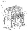
- FIG. 1 illustrates a perspective view of a circuit breaker assembly 100 in accordance with exemplary embodiments.
- the assembly 100 includes a breaker housing 105, a circuit breaker 150 disposed within the housing 105 and a lay shaft 110 disposed within the housing 105 and coupled to the circuit breaker 150.
- the circuit breaker 150 further includes a lifting plate (vertical lever) 152 disposed adjacent a side wall 170 of the circuit breaker 150.
- the lifting plate 152 includes a lifting plate slot 160 disposed on one end of the lifting plate 152. As described further herein the lifting plate slot is configured to receive a key lock lever (161, see FIG.6 ).
- the circuit breaker 150 further includes a padlock plate 153 disposed adjacent the sidewall 170. The lifting plate 152 and the padlock plate 153 are coupled to Trip paddle 154.
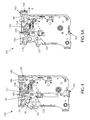
- FIG. 2 illustrates a side view of the circuit breaker mechanism 150 in an OFF condition in accordance with exemplary embodiments.
- FIG. 3A illustrates a side view of the lifting plate 152
- FIG 3B illustrates a side view of the padlock plate 153.
- the circuit breaker mechanism 150 includes the lifting plate 152, the trip paddle 154 and the padlock plate 153.
- the trip paddle 154 is disposed in between the lifting plate 152 and the padlock plate 153.
- the lifting plate 152 further includes a lifting roller 156, a blocking cam profile 159 and the lifting plate slot 160.
- the padlock plate 153 includes a grip 165, padlock apertures 166, a padlock pin 157 and a padlock lifting profile 158.
- the grip can be engaged by a user to shift the padlock plate 153 outwards from the circuit breaker 150 along the sidewall 170.
- a padlock or other locking mechanism can be inserted into the padlock apertures 166 when the padlock plate 153 is pulled outwards in this manner.
- the padlock pin 157 is configured to engage and rotate the trip paddle.
- the lay shaft 110 includes a cam plate 151, which further includes a blocking pin 155.
- FIG. 2 illustrates the circuit breaker 150 in the OFF position, with the contacts open.
- FIG. 2 further illustrates the circuit breaker in an un-padlocked state in which the lifting plate 152 and the padlock plate 153 have not been engaged to lock the circuit breaker into a locked OFF position.
- the padlock plate profile 158 urges the lifting plate roller 156 upwards.
- this motion is prevented when the circuit breaker is in the ON condition as now described.
- FIG. 4 illustrates a side view of the circuit breaker 150 in an ON condition in accordance with exemplary embodiments.
- the contacts are in contact and the lay shaft 110 is rotated such that the blocking pin 155 on the lay shaft cam 151 is rotated toward the lifting plate 152 and adjacent the lifting profile 159.
- an upward motion of the lifting plate 153 i.e., the lifting profile 159 is impeded, or blocked by the blocking pin 155 on the lay shaft cam 151 (i.e., when the blocking pin 155 and the lifting profile 159 are in mechanical contact).
- the lifting plate roller 156 of the lifting plate 152 is coupled to the padlock plate profile 158 of the padlock plate 153.
- the lifting plate cannot be displaced upward when the contacts are in the closed (i.e., when the circuit breaker 150 is in the ON condition).
- the blocking pin 155 restraining the lifting plate 152, a user is unable to pull the padlock plate 153 outwards because the lifting plate roller 156 is also restrained from displacement upwards, the direction to which the padlock plate profile 158 would direct the lifting plate roller 156.
- a user is unable to padlock the circuit breaker 150.
- a user is unable to place a key lock lever 161 into the lifting plate slot 160 (described further with respect to FIG. 6 ) as the lifting plate 152 upward displacement is prevented.
- a trip free lock can be coupled to the circuit breaker 150.
- the circuit breaker 150 is to be placed and remain placed in an OFF condition when a trip free lock is placed on the circuit breaker 150.
- the exemplary systems described herein prevent the circuit breaker from being placed in the on condition when the circuit breaker is padlocked or otherwise locked as now described.
- FIG. 5A illustrates a side view of the circuit breaker 150 in an OFF condition in accordance with exemplary embodiments.
- FIG. 5 illustrated a padlock-applied condition with the circuit breaker in the OFF condition.
- the lay shaft 110 is rotated such that the lay shaft cam 151 and the blocking pin 155 are rotated away from the lifting plate 152.
- the blocking pin does not impede the upward displacement of the lifting plate 152 via the lifting profile 159 as described above.
- the padlock pin 157 rotates the trip paddle 154 and keeps the trip paddle 154 in a trip free condition.
- the padlock plate profile 158 lifts the lifting plate 152 via the lifting plate roller 156.
- a user can apply a padlock to the padlock apertures 166 as well an inserting a key lock lever 161 into the lifting plate slot 160 (see FIG. 6 ). It is therefore appreciated that when a user desires to padlock the circuit breaker in a trip free and OFF condition, the user switches the circuit breaker to an OFF condition in which the contacts are open, and then pulls the padlock plate 153 as described, and further locks the circuit breaker as described.
- FIGS. 5B-5C illustrate perspective side views of the circuit breaker mechanism 150 in a trip-free condition.
- the circuit breaker mechanism 150 further includes a trip free plate 173 coupled to a trip free pin 178 configured to engage a close paddle 172 coupled to a closing shaft 174.
- the a closing shaft 174 is further coupled to a closing coupler 173 having a closing coupler profile 179.
- a trip shaft is coupled to the trip paddle 154 and to a latch 176.
- the circuit breaker mechanism 150 further includes a push on lever 177.
- the latch 176 has to be released.
- the closing shaft 174 is rotated.
- a user presses the push on lever 177.
- the closing coupler 173 is rotated.
- the closing coupler profile 179 engages the trip free pin 178, which in turn, engages the closing paddle 172.
- the engagement of the closing paddle 172 results in a rotation of the closing shaft 174 thereby closing the latch 176, which is delatched.
- a trip free condition results by the application of a padlock, the circuit breaker mechanism 150 being in a closed condition, the application of some other interlock or the main springs (not shown) of the circuit breaker mechanism 150 being not charged (compressed).
- the trip free plate 171 is moved to outwards.
- the closing coupler profile 179 cannot engage the trip free pin 178.
- the closing shaft 174 cannot be rotated, as there is no coupling between the trip free pin 178 and closing paddle 172.
- a racking handle (not shown) is engaged to rack out and rack in the circuit breaker assembly 100.
- the lifting plate 152 us lifted up in order to engage the racking handle. As such, the circuit breaker mechanism is placed into an OFF condition in order to rack out and rack in.
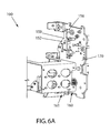
- FIGS. 6A-6B illustrate a perspective side views of a circuit breaker 150 mechanism in accordance with exemplary embodiments.
- the lay shaft 110 is prevented from rotating and thus the circuit breaker is locked into a trip free condition at which time a padlock can be inserted into the padlock apertures 166.
- the key lock lever 161 can be inserted into the lifting plate slot 160 via interlock keys 180, which locks the lifting plate 152 in the upwardly displaced position, thereby keeping the breaker in a trip free condition.
- the padlock pin 157 engages and rotates the trip paddle 154, thereby retaining the trip shaft in the rotated position as described.
- the user can then engage the locking mechanism.
- a padlock can be inserted into the padlock apertures 166.
- the key lock lever 161 can be inserted into the lifting plate slot 160.
- the user can perform breaker operations that require the circuit breaker 150 to be retained in the OFF condition such as moving the circuit breaker 150 or performing maintenance on the circuit breaker 150.
Landscapes
- Engineering & Computer Science (AREA)
- Computer Security & Cryptography (AREA)
- Driving Mechanisms And Operating Circuits Of Arc-Extinguishing High-Tension Switches (AREA)
- Breakers (AREA)
- Trip Switchboards (AREA)
- Switch Cases, Indication, And Locking (AREA)
Applications Claiming Priority (1)
| Application Number | Priority Date | Filing Date | Title |
|---|---|---|---|
| US12/103,225 US7943873B2 (en) | 2008-04-15 | 2008-04-15 | Circuit breaker with locking mechanism |
Publications (2)
| Publication Number | Publication Date |
|---|---|
| EP2110909A2 true EP2110909A2 (de) | 2009-10-21 |
| EP2110909A3 EP2110909A3 (de) | 2011-11-09 |
Family
ID=40852261
Family Applications (1)
| Application Number | Title | Priority Date | Filing Date |
|---|---|---|---|
| EP09157487A Withdrawn EP2110909A3 (de) | 2008-04-15 | 2009-04-07 | Schutzschalter mit Sperrmechanismus |
Country Status (4)
| Country | Link |
|---|---|
| US (1) | US7943873B2 (de) |
| EP (1) | EP2110909A3 (de) |
| JP (1) | JP5337564B2 (de) |
| CN (1) | CN101615533B (de) |
Cited By (1)
| Publication number | Priority date | Publication date | Assignee | Title |
|---|---|---|---|---|
| EP3131106A1 (de) * | 2015-08-10 | 2017-02-15 | ABB Schweiz AG | Verriegelungsvorrichtung für eine hochspannungsschaltanlage |
Families Citing this family (10)
| Publication number | Priority date | Publication date | Assignee | Title |
|---|---|---|---|---|
| KR101300979B1 (ko) * | 2009-11-03 | 2013-08-27 | 미쓰비시덴키 가부시키가이샤 | 개폐장치의 조작기구 |
| KR101060786B1 (ko) * | 2009-11-19 | 2011-08-30 | 엘에스산전 주식회사 | 회로 차단기의 잠금 장치 |
| EP2538424B1 (de) * | 2011-06-22 | 2016-08-10 | ABB S.p.A. | Schaltvorrichtung und zugehöriges Energieverteilungssystem |
| CN103700537B (zh) * | 2011-09-29 | 2015-10-28 | 巨邦电气集团有限公司 | 一种户内高压真空断路器 |
| US9299522B2 (en) | 2012-09-28 | 2016-03-29 | General Electric Company | Shutter locking mechanism for circuit breaker assembly |
| US10157721B2 (en) | 2016-04-07 | 2018-12-18 | DEA Incorporated | Electrical breaker rear side actuator |
| US9842708B1 (en) | 2016-06-03 | 2017-12-12 | General Electric Company | Circuit breaker latch mechanism integrated into the rotor assembly |
| JP7274413B2 (ja) | 2016-09-23 | 2023-05-16 | マレンゴ・セラピューティクス,インコーポレーテッド | ラムダ及びカッパ軽鎖を含む多重特異性抗体分子 |
| CN111211018B (zh) * | 2020-03-31 | 2025-04-29 | 贵州泰永长征技术股份有限公司 | 一种插入式小型断路器 |
| CN114843153A (zh) * | 2022-05-25 | 2022-08-02 | 浙江西屋电气股份有限公司 | 一种小型断路器防误合闸装置 |
Family Cites Families (4)
| Publication number | Priority date | Publication date | Assignee | Title |
|---|---|---|---|---|
| US4001742A (en) * | 1975-10-30 | 1977-01-04 | General Electric Company | Circuit breaker having improved operating mechanism |
| FR2701617B1 (fr) * | 1993-02-16 | 1995-04-14 | Merlin Gerin | Disjoncteur à télécommande et à fonction de sectionnement. |
| US5782341A (en) * | 1995-12-22 | 1998-07-21 | General Electric Company | Padlocking arrangement for high ampere-rated circuit breaker |
| US6472620B2 (en) * | 2000-03-17 | 2002-10-29 | Ge Power Controls France Sas | Locking arrangement for circuit breaker draw-out mechanism |
-
2008
- 2008-04-15 US US12/103,225 patent/US7943873B2/en not_active Expired - Fee Related
-
2009
- 2009-04-07 EP EP09157487A patent/EP2110909A3/de not_active Withdrawn
- 2009-04-10 JP JP2009096158A patent/JP5337564B2/ja not_active Expired - Fee Related
- 2009-04-15 CN CN2009101351911A patent/CN101615533B/zh not_active Expired - Fee Related
Cited By (2)
| Publication number | Priority date | Publication date | Assignee | Title |
|---|---|---|---|---|
| EP3131106A1 (de) * | 2015-08-10 | 2017-02-15 | ABB Schweiz AG | Verriegelungsvorrichtung für eine hochspannungsschaltanlage |
| US9875868B2 (en) | 2015-08-10 | 2018-01-23 | Abb Schweiz Ag | Locking device for high-voltage switchgear |
Also Published As
| Publication number | Publication date |
|---|---|
| CN101615533B (zh) | 2013-11-20 |
| JP5337564B2 (ja) | 2013-11-06 |
| EP2110909A3 (de) | 2011-11-09 |
| CN101615533A (zh) | 2009-12-30 |
| JP2009259821A (ja) | 2009-11-05 |
| US7943873B2 (en) | 2011-05-17 |
| US20090255786A1 (en) | 2009-10-15 |
Similar Documents
| Publication | Publication Date | Title |
|---|---|---|
| US7943873B2 (en) | Circuit breaker with locking mechanism | |
| CA1289607C (en) | Draw-in and draw-out mechanism of an electrical circuit breaker with main and auxiliary circuits | |
| CN102842444B (zh) | 开关装置 | |
| US6184483B1 (en) | Plug-in circuit breaker comprising an operating lever for opening and closing of poles | |
| EP3703096B1 (de) | Verriegelungsvorrichtung für schalterbetätigungsgerät | |
| CN102842445B (zh) | 开关装置以及相关的电力分配系统和风力发电厂 | |
| EP2472547B1 (de) | Sperrvorrichtung zur Verwendung in einem Schutzschalter und Montageverfahren | |
| EP3427356B1 (de) | Ausfahrverriegelungssystem für ausfahrbare leistungsschalter | |
| CN108565185B (zh) | 漏电断路器的漏电指示保护机构以及漏电指示保护方法 | |
| CN207398694U (zh) | 一种开关设备的联锁装置 | |
| KR20220135013A (ko) | 인터록 장치를 갖는 기중차단기 | |
| CN206657757U (zh) | 断路器出线联锁机构 | |
| KR200476959Y1 (ko) | 진공차단기의 3-포지션 인출입장치 | |
| CN101136539A (zh) | 用于电开关装置的锁具 | |
| CN108597942B (zh) | 柱上开关的合闸互锁机构 | |
| CN201532894U (zh) | 隔离开关机构的连锁装置 | |
| CN114078639B (zh) | 用于低压、中压或高压开关设备的隔室的手柄 | |
| CN113302809B (zh) | 空气绝缘配电盘的接地模块 | |
| CN209962911U (zh) | 一种固定式断路器紧急分闸机械联锁装置 | |
| CN108899243B (zh) | 联锁机构及高压开关设备 | |
| KR20090109506A (ko) | 로킹 기구를 갖는 회로 차단기 | |
| KR200440691Y1 (ko) | 투입방지장치를 구비한 진공차단기 | |
| US2916571A (en) | Circuit breaker truck position interlock | |
| CN108807037B (zh) | 柱上开关的分闸互锁机构 | |
| CN113990688B (zh) | 一种用于开关设备的柜门联锁装置及开关设备 |
Legal Events
| Date | Code | Title | Description |
|---|---|---|---|
| PUAI | Public reference made under article 153(3) epc to a published international application that has entered the european phase |
Free format text: ORIGINAL CODE: 0009012 |
|
| AK | Designated contracting states |
Kind code of ref document: A2 Designated state(s): AT BE BG CH CY CZ DE DK EE ES FI FR GB GR HR HU IE IS IT LI LT LU LV MC MK MT NL NO PL PT RO SE SI SK TR |
|
| PUAL | Search report despatched |
Free format text: ORIGINAL CODE: 0009013 |
|
| AK | Designated contracting states |
Kind code of ref document: A3 Designated state(s): AT BE BG CH CY CZ DE DK EE ES FI FR GB GR HR HU IE IS IT LI LT LU LV MC MK MT NL NO PL PT RO SE SI SK TR |
|
| AX | Request for extension of the european patent |
Extension state: AL BA RS |
|
| RIC1 | Information provided on ipc code assigned before grant |
Ipc: H01H 9/28 20060101ALI20110930BHEP Ipc: H01H 71/10 20060101ALI20110930BHEP Ipc: H01H 3/42 20060101ALI20110930BHEP Ipc: H02B 11/133 20060101AFI20110930BHEP |
|
| 17P | Request for examination filed |
Effective date: 20120509 |
|
| 17Q | First examination report despatched |
Effective date: 20150108 |
|
| STAA | Information on the status of an ep patent application or granted ep patent |
Free format text: STATUS: THE APPLICATION IS DEEMED TO BE WITHDRAWN |
|
| 18D | Application deemed to be withdrawn |
Effective date: 20150519 |