EP2110942A2 - Procédé de détection de l'état de perte de synchronisation dans un moteur pas à pas - Google Patents
Procédé de détection de l'état de perte de synchronisation dans un moteur pas à pas Download PDFInfo
- Publication number
- EP2110942A2 EP2110942A2 EP09005045A EP09005045A EP2110942A2 EP 2110942 A2 EP2110942 A2 EP 2110942A2 EP 09005045 A EP09005045 A EP 09005045A EP 09005045 A EP09005045 A EP 09005045A EP 2110942 A2 EP2110942 A2 EP 2110942A2
- Authority
- EP
- European Patent Office
- Prior art keywords
- back emf
- phase
- stepping motor
- emf voltage
- synchronization loss
- Prior art date
- Legal status (The legal status is an assumption and is not a legal conclusion. Google has not performed a legal analysis and makes no representation as to the accuracy of the status listed.)
- Granted
Links
Images


Classifications
-
- H—ELECTRICITY
- H02—GENERATION; CONVERSION OR DISTRIBUTION OF ELECTRIC POWER
- H02P—CONTROL OR REGULATION OF ELECTRIC MOTORS, ELECTRIC GENERATORS OR DYNAMO-ELECTRIC CONVERTERS; CONTROLLING TRANSFORMERS, REACTORS OR CHOKE COILS
- H02P8/00—Arrangements for controlling dynamo-electric motors rotating step by step
- H02P8/36—Protection against faults, e.g. against overheating or step-out; Indicating faults
- H02P8/38—Protection against faults, e.g. against overheating or step-out; Indicating faults the fault being step-out
-
- H—ELECTRICITY
- H02—GENERATION; CONVERSION OR DISTRIBUTION OF ELECTRIC POWER
- H02P—CONTROL OR REGULATION OF ELECTRIC MOTORS, ELECTRIC GENERATORS OR DYNAMO-ELECTRIC CONVERTERS; CONTROLLING TRANSFORMERS, REACTORS OR CHOKE COILS
- H02P8/00—Arrangements for controlling dynamo-electric motors rotating step by step
- H02P8/32—Reducing overshoot or oscillation, e.g. damping
-
- H—ELECTRICITY
- H02—GENERATION; CONVERSION OR DISTRIBUTION OF ELECTRIC POWER
- H02P—CONTROL OR REGULATION OF ELECTRIC MOTORS, ELECTRIC GENERATORS OR DYNAMO-ELECTRIC CONVERTERS; CONTROLLING TRANSFORMERS, REACTORS OR CHOKE COILS
- H02P8/00—Arrangements for controlling dynamo-electric motors rotating step by step
- H02P8/34—Monitoring operation
-
- H—ELECTRICITY
- H02—GENERATION; CONVERSION OR DISTRIBUTION OF ELECTRIC POWER
- H02P—CONTROL OR REGULATION OF ELECTRIC MOTORS, ELECTRIC GENERATORS OR DYNAMO-ELECTRIC CONVERTERS; CONTROLLING TRANSFORMERS, REACTORS OR CHOKE COILS
- H02P8/00—Arrangements for controlling dynamo-electric motors rotating step by step
- H02P8/36—Protection against faults, e.g. against overheating or step-out; Indicating faults
Definitions
- the present invention relates to a method of detecting a state of synchronization loss in a stepping motor. Specifically, the present invention relates to a method of detecting a state of synchronization loss, in which the state of synchronization loss in an N-phase stepping motor is detected by using a means for applying either control current or voltage to a coil of each phase to thereby drive the N-phase stepping motor and a means for individually measuring a back EMF voltage induced at the coil of each phase.
- Fig. 1 shows an outline of an electric circuit of a stepping motor 1.
- the stepping motor 1 is a two phase bipolar stepping motor driven by two-phase (phase A and phase B) excitation.
- the stepping motor 1 includes: a rotor 3 having a permanent magnet with a multipole magnetization arranged such that two kinds of magnetic poles (N, S) 2 are alternately arrayed in the circumferential direction; at least two stator yokes disposed around the rotor 3 so as to form a multiphase magnetic field with at least two phase;, and coils 4 to excite the stator yokes.
- pulsed control signals (1a, 1b) are applied to the coils 4 by a driving circuit 5, the rotor 3 is caused to rotate according to a predetermined step unit, wherein the rotation angle and the rotation speed of the rotor 3 can be highly precisely controlled by the number and cycle of pulse signals.
- the stepping motor while advantageous in that thanks to its structure the rotor is free from mechanical contact with the stator thus enabling a long life and in that a large static torque can be produced at the time of excitation, has the problem that the rotor fails to normally rotate when the pulse signal has a short cycle or when the load is large, thus causing a so-called synchronization loss.
- the stepping motor is frequently used for precisely controlling the rotation angle and speed, and therefore, when the stepping motor loses synchronization, it is necessary to detect the malfunction state immediately and then perform an error handling procedure, such as halt of the rotation or restoration to the normal rotation.
- the stepping motor is often equipped with a circuit or a system for detecting a state of synchronization loss and then performing an error handling procedure.
- EP1460757 discloses a method of precisely detecting a state of synchronization loss in such a manner that a control signal is halted in each step unit for such a short period of time as not to affect the motor rotation wherein a back EMF voltage induced at a coil is measured during the period of time.
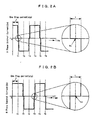
- Figs. 2A and 2B outline the technique of detecting a state of synchronization loss disclosed in European Patent Application Laid-Open No. EP1460757 , wherein control signal waveforms (control current waveforms) of a two-phase stepping motor are shown. It is arranged at each of Phases A and B that each control signal is halted at a predetermined timing in each step period (stp) for such a minute period of time (halt time) (t) as not to affect the motor rotation.
- the halt time t is provided before and after each of inversion timings (T1 to T6) at which current polarity is changed, and a back EMF voltage is measured during the halt time (t).
- the above described methods of detecting a state of synchronization loss may employ an external circuit provided outside, may be incorporated into an IC as an algorithm of a program, or may be installed as a software of a computer, wherein back EMF voltage signals from the coil or data corresponding to the signal are inputted to the electric circuit, the IC or the computer, and if the state of synchronization loss is detected, then a detection signal for indicating synchronization loss is outputted. After the detection signal is outputted, an appropriate error handling procedure is performed, for example, a driving circuit to generate a control signal is to be feedback-controlled according to the detection signal.
- the present inventors, et al made a field-investigation into the conventional methods of detecting synchronization loss and found out that it happens with a high probability that the circuit functions improperly such that synchronization loss is judged to occur even prior to actually occurring or fails to be detected in spite of actually occurring.
- et al conducted a simulation for detecting synchronization loss according to the method described in European Patent Application Laid-Open No. EP1460757 .
- a gear box was combined with the stepping motor 1 shown in Fig. 1 thereby providing an actuator, and the back EMF voltages (VA, VB) were measured at the time of increasingly applying a torque load to the output gear of the actuator as well as at the time of locking the output gear, that is, at the state of synchronization loss, and the result gained when the algorithm based on the method described in European Patent Application Laid-Open No. EP1460757 was applied was simulated.
- the present inventors, et al assumed that in order to detect synchronization loss of a stepping motor with an enhanced precision, it is necessary to closely analyze a back EMF voltage and its fluctuation mode at the time of synchronization loss in addition to employing an optical method of measuring a back EMF voltage, and continued studying the back EMF voltage at the time of synchronization loss.
- the value of back EMF voltage or the fluctuation pattern thereof at the time of synchronization loss are not uniform but diversified.
- the present invention has been made in light of the problems described above and also made based on the above findings, and it is an object of the present invention to provide a method of detecting a state of synchronization loss, which is performed based on a back EMF voltage induced at a coil, and in which the state of synchronization loss can be precisely detected while the maximum motor torque can be fully utilized.
- a method of detecting a state of synchronization loss in a stepping motor in which a means for applying either control current or control voltage to a coil of each phase to thereby drive an N-phase stepping motor and a means for individually measuring a back EMF voltage induced at the coil of each phase are employed, wherein application of either the control current or the control voltage at the coil of each phase is halted by turns phase by phase for such a short period of time as not to affect the rotation of a rotor of the stepping motor at a predetermined timing within one step period of the rotor, the back EMF voltage at the coil is measured during the short period of time, and the stepping motor is judged to lose synchronization when the measurement result of the back EMF voltage at the coil of at least one phase satisfies a predetermined detection criterion.
- the detection criterion may be defined by any one of (A) to (D) which follow below:
- the detection criterion may be further defined such that any one of the above described (A) to (C) is combined with either (E), (E) and (F), or (E) to (G):
- the state of synchronization loss can be further precisely detected while the maximum motor torque can be fully utilized.
- Fig. 1 is a circuit diagram of a two-phase stepping motor
- Figs. 2A and 2B are schematic views of a method of measuring a back EMF voltage in a method of detecting a state of synchronization loss according to the present invention
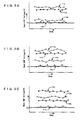
- Figs. 3A to 3C are graphs of fluctuation patterns of back EMF voltages at respective phases obtained when the stepping motor rotates normally
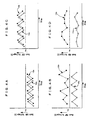
- Figs. 4A to 4D are graphs of fluctuation patterns of back EMF voltages at the respective phases obtained when the stepping motor loses synchronization
- Figs. 5A to 5E are schematic graphs of detection criteria for the state of synchronization loss.
- the present invention may be embodied, for example, by means of an IC provided with a program to control a stepping motor according to an algorithm according to the present invention, to measure a back EMF voltage at a coil of each phase, and also to judge the state of synchronization loss based on the measurement result, and by means of a computer having the above described program installed therein, wherein the IC and the computer are adapted to measure the back EMF voltage by running the program, and if the measurement result indicates the state of synchronization loss, then an appropriate indication is outputted exactly when the indication signal is detected.
- a signal halt time period is provided at each step period (stp) so as to appear alternately at phase A and phase B as shown in Figs. 2A and 2B , and the back EMF voltage at the signal halt time period is measured phase by phase.
- the fluctuation of a back EMF voltage induced at a coil of each phase of a two-phase stepping motor was measured when a rotor was rotating normally.
- an actuator was constituted by a stepping motor and a gear box as described above, and the back EMF voltage was measured at each of phase A and phase, B when the maximum load to allow a motor rotation was applied to the output gear of the actuator (under load) and also when no load was applied to the output gear of the actuator (under no load).
- the measurement results are shown in graphs of Figs. 3A to 3C .
- the back EMF voltage value marked by Va is the minimum value which is obtained when the rotor was rotating and which is a threshold value as a benchmark for detecting synchronization loss.
- Fig. 4A shows that both back EMF voltages (12a, 12b) at Phase A and Phase B rise and fall alternately at each measuring point wherein both thereof stay at or below the threshold value Va
- Fig. 4B shows that both back EMF voltages (12a, 12b) at Phase A and Phase B rise and fall alternately at each measuring point wherein one (12a) of both thereof stays at or below the threshold value Va
- Fig. 4A shows that both back EMF voltages (12a, 12b) at Phase A and Phase B rise and fall alternately at each measuring point wherein one (12a) of both thereof stays at or below the threshold value Va
- Fig. 4B shows that both back EMF voltages (12a, 12b) at Phase A and Phase B rise and fall alternately at each measuring point wherein one (12a) of both thereof stays at or below the threshold value Va
- Fig. 4A shows that both back EMF voltages (12a, 12b) at Phase A and Phase B rise and fall alternately at each measuring point wherein one (12a) of both thereof stays at or below
- FIG. 4C shows that back EMF voltages (12a, 12b) at Phase A and Phase B rise and fall alternately at each measuring point wherein both thereof stay at or above the threshold value Va
- Fig. 4D shows that both back EMF voltages (12a, 12b) at Phase A and Phase B rise and fall irregularly at each measuring point wherein one (12a) of both thereof stays at or below the threshold value Va.
- the result here characteristically shows that the fluctuation value of the back EMF voltage is larger when the motor loses synchronization than when the motor rotates normally.
- Criteria (1) to (5) described below refer to examples of detecting a state of synchronization loss and will be explained with reference to Figs. 5A to 5E , respectively.
- Criteria (1) and (2) are defined such that the back EMF voltage measures at or below the threshold value Va for at least two times, but the present invention is not limited to such a definition and the state of synchronization loss may be judged to occur when the back EMF voltage once measures at or below the threshold value Va. Also, the present invention is not limited in the combination of a plurality of detection criteria to the definitions of Criteria (6) and (7). By appropriately combining the detection criteria, it can be expected that the state of synchronization is detected with a probability of close to 100%. Needless to say, the state of synchronization loss may be judged to occur when any one of all the criteria is satisfied. If the arrangement is made such that the state of synchronization is judged to occur when any one of a plurality of criteria is satisfied, it is advantageous in saving the time between the actual occurrence of synchronization loss and the detection of synchronization loss.
- the state of synchronization loss can be judged to occur when the back EMF voltage at any one phase satisfies the criteria, and therefore the method can be applied to not only a two-phase stepping motor but also an N-phase stepping motor.
- the present invention is not limited in the timing of measurement of the back EMF voltage to the timings (T1 to T6 in Figs. 2A and 2B ) at which the polarity of control current flowing at each coil is reversed, and the back EMF voltage can be measured at any arbitrary timing within one step period (stp) on the assumption that the halt time (t) is such a short period of time as not to affect the motor rotation.
Landscapes
- Engineering & Computer Science (AREA)
- Power Engineering (AREA)
- Control Of Stepping Motors (AREA)
Applications Claiming Priority (1)
| Application Number | Priority Date | Filing Date | Title |
|---|---|---|---|
| JP2008103830A JP5331370B2 (ja) | 2008-04-11 | 2008-04-11 | ステッピングモータの脱調状態検出方法 |
Publications (3)
| Publication Number | Publication Date |
|---|---|
| EP2110942A2 true EP2110942A2 (fr) | 2009-10-21 |
| EP2110942A3 EP2110942A3 (fr) | 2015-08-19 |
| EP2110942B1 EP2110942B1 (fr) | 2017-11-08 |
Family
ID=41050525
Family Applications (1)
| Application Number | Title | Priority Date | Filing Date |
|---|---|---|---|
| EP09005045.1A Active EP2110942B1 (fr) | 2008-04-11 | 2009-04-06 | Procédé de détection de l'état de perte de synchronisation dans un moteur pas à pas |
Country Status (3)
| Country | Link |
|---|---|
| US (1) | US8174223B2 (fr) |
| EP (1) | EP2110942B1 (fr) |
| JP (1) | JP5331370B2 (fr) |
Cited By (2)
| Publication number | Priority date | Publication date | Assignee | Title |
|---|---|---|---|---|
| CN110022099A (zh) * | 2019-04-29 | 2019-07-16 | 青岛海信日立空调系统有限公司 | 一种永磁同步电机失步的检测方法及装置 |
| WO2024179757A1 (fr) * | 2023-03-01 | 2024-09-06 | Shl Medical Ag | Procédé de détection d'un état de calage d'un moteur pas à pas rotatif |
Families Citing this family (16)
| Publication number | Priority date | Publication date | Assignee | Title |
|---|---|---|---|---|
| DE102010000286B4 (de) * | 2009-02-05 | 2019-05-23 | Denso Corporation | Anzeigeinstrument für ein Fahrzeug |
| JP5591508B2 (ja) * | 2009-09-18 | 2014-09-17 | セミコンダクター・コンポーネンツ・インダストリーズ・リミテッド・ライアビリティ・カンパニー | ドライバ回路 |
| JP5697320B2 (ja) * | 2009-09-18 | 2015-04-08 | セミコンダクター・コンポーネンツ・インダストリーズ・リミテッド・ライアビリティ・カンパニー | ドライバ回路 |
| JP5591507B2 (ja) * | 2009-09-18 | 2014-09-17 | セミコンダクター・コンポーネンツ・インダストリーズ・リミテッド・ライアビリティ・カンパニー | ドライバ回路 |
| US8242732B2 (en) * | 2009-12-18 | 2012-08-14 | Xylon d.o.o. | Apparatus, system and method for stepper motor stall detection |
| JP5786283B2 (ja) * | 2010-06-04 | 2015-09-30 | 株式会社リコー | モータ制御装置、画像形成装置及びモータ制御方法 |
| JP2012016221A (ja) | 2010-07-02 | 2012-01-19 | Minebea Co Ltd | モータ制御装置及び脱調状態検出方法 |
| JP5936883B2 (ja) * | 2012-03-02 | 2016-06-22 | ミネベア株式会社 | モータ制御装置及びステッピングモータの脱調状態判定方法 |
| JP2014128070A (ja) | 2012-12-25 | 2014-07-07 | Minebea Co Ltd | モータ制御装置及びステッピングモータの制御方法 |
| JP2015142441A (ja) | 2014-01-29 | 2015-08-03 | ミネベア株式会社 | モータ制御装置および脱調状態検出方法 |
| JP6537347B2 (ja) * | 2015-05-14 | 2019-07-03 | 大和製衡株式会社 | 組合せ秤 |
| JP2017038492A (ja) * | 2015-08-12 | 2017-02-16 | 株式会社メレック | ステッピングモータの脱調判定装置及び脱調判定方法 |
| JP6548619B2 (ja) * | 2016-08-31 | 2019-07-24 | ミネベアミツミ株式会社 | モータ制御装置および脱調状態検出方法 |
| JP6727173B2 (ja) | 2017-08-18 | 2020-07-22 | 株式会社東芝 | ロータ位置検出システム |
| JP7129802B2 (ja) * | 2018-03-23 | 2022-09-02 | ミネベアミツミ株式会社 | モータ制御装置、ステッピングモータシステム及びモータ制御方法 |
| CN110076412B (zh) * | 2019-04-16 | 2021-08-06 | 深圳市麦格米特焊接技术有限公司 | 一种双电机协同控制方法、装置、电机控制器和送丝系统 |
Citations (3)
| Publication number | Priority date | Publication date | Assignee | Title |
|---|---|---|---|---|
| JP2000126297A (ja) | 1998-10-27 | 2000-05-09 | Siemens Elema Ab | 麻酔器 |
| JP2000166297A (ja) | 1998-11-27 | 2000-06-16 | Seiko Epson Corp | ステッピングモータの駆動装置および駆動機構 |
| EP1460757A1 (fr) | 2003-03-21 | 2004-09-22 | AMI Semiconductor Belgium BVBA | Dispositif et procédé de detection de vitesse du rotor d'un moteur à phases multiples avec entrainement bipolaire |
Family Cites Families (11)
| Publication number | Priority date | Publication date | Assignee | Title |
|---|---|---|---|---|
| US4283783A (en) * | 1978-11-28 | 1981-08-11 | Citizen Watch Company Limited | Drive control system for stepping motor |
| JPS60257793A (ja) * | 1984-06-01 | 1985-12-19 | Matsushita Electric Ind Co Ltd | ステツピングモ−タの回転検出装置 |
| US4743848A (en) * | 1986-07-17 | 1988-05-10 | International Business Machines Corporation | Method of testing a stepping motor |
| JPH0750998B2 (ja) * | 1989-01-09 | 1995-05-31 | アスモ株式会社 | ステップモータの異常検出装置 |
| JPH07131997A (ja) * | 1993-11-05 | 1995-05-19 | Yamaha Motor Co Ltd | ステップモータの回転状態検出装置 |
| JPH0898597A (ja) * | 1994-09-16 | 1996-04-12 | Nissan Motor Co Ltd | ステップモータ制御装置 |
| DE19860110A1 (de) * | 1998-12-23 | 2000-07-06 | Mannesmann Vdo Ag | Verfahren zur Überwachung der Drehzahl eines Synchronmotors und Vorrichtung zur Überwachung der Drehzahl eines derartigen Motors |
| US6586898B2 (en) * | 2001-05-01 | 2003-07-01 | Magnon Engineering, Inc. | Systems and methods of electric motor control |
| JP2002365379A (ja) * | 2001-06-11 | 2002-12-18 | Seiko Instruments Inc | アナログ電子時計 |
| JP5559504B2 (ja) * | 2009-09-30 | 2014-07-23 | セミコンダクター・コンポーネンツ・インダストリーズ・リミテッド・ライアビリティ・カンパニー | モータ駆動制御回路 |
| US8242732B2 (en) * | 2009-12-18 | 2012-08-14 | Xylon d.o.o. | Apparatus, system and method for stepper motor stall detection |
-
2008
- 2008-04-11 JP JP2008103830A patent/JP5331370B2/ja active Active
-
2009
- 2009-03-25 US US12/382,853 patent/US8174223B2/en active Active
- 2009-04-06 EP EP09005045.1A patent/EP2110942B1/fr active Active
Patent Citations (3)
| Publication number | Priority date | Publication date | Assignee | Title |
|---|---|---|---|---|
| JP2000126297A (ja) | 1998-10-27 | 2000-05-09 | Siemens Elema Ab | 麻酔器 |
| JP2000166297A (ja) | 1998-11-27 | 2000-06-16 | Seiko Epson Corp | ステッピングモータの駆動装置および駆動機構 |
| EP1460757A1 (fr) | 2003-03-21 | 2004-09-22 | AMI Semiconductor Belgium BVBA | Dispositif et procédé de detection de vitesse du rotor d'un moteur à phases multiples avec entrainement bipolaire |
Cited By (2)
| Publication number | Priority date | Publication date | Assignee | Title |
|---|---|---|---|---|
| CN110022099A (zh) * | 2019-04-29 | 2019-07-16 | 青岛海信日立空调系统有限公司 | 一种永磁同步电机失步的检测方法及装置 |
| WO2024179757A1 (fr) * | 2023-03-01 | 2024-09-06 | Shl Medical Ag | Procédé de détection d'un état de calage d'un moteur pas à pas rotatif |
Also Published As
| Publication number | Publication date |
|---|---|
| US20090256515A1 (en) | 2009-10-15 |
| EP2110942A3 (fr) | 2015-08-19 |
| JP5331370B2 (ja) | 2013-10-30 |
| EP2110942B1 (fr) | 2017-11-08 |
| US8174223B2 (en) | 2012-05-08 |
| JP2009261045A (ja) | 2009-11-05 |
Similar Documents
| Publication | Publication Date | Title |
|---|---|---|
| EP2110942B1 (fr) | Procédé de détection de l'état de perte de synchronisation dans un moteur pas à pas | |
| EP0462729B1 (fr) | Méthode et appareil de détection de la position du rotor d'un moteur à courant continu sans balai | |
| US8058894B2 (en) | Method for detecting a fault condition | |
| US8754640B2 (en) | Magnetic field sensors and related techniques that can provide self-test information in a formatted output signal | |
| US5001405A (en) | Position detection for a brushless DC motor | |
| EP0517393B1 (fr) | Méthode pour déterminer la direction de rotation au démarrage d' un moteur polyphasé à courant continu sans balai et système de commande pour cela | |
| US8040095B2 (en) | Synchronization of sequential phase switchings in driving stator windings of a multiphase sensorless brushless motor at sub BEMF-detectability speeds | |
| US20110260748A1 (en) | Apparatus and method for diagnosing permanent magnet demagnetization of permanent magnet synchronous motor, and apparatus for driving permanent magnet synchronous motor | |
| US7622882B2 (en) | Position detection device for permanent magnetic machines | |
| DE102009030884A1 (de) | Verfahren und Einrichtung zur Kompensation von Lasteinflüssen bei permanenterregten Motoren | |
| US8907606B2 (en) | Method and device for determining a rotor position of a synchronous machine | |
| US8896257B2 (en) | Motor control device and out-of-step detecting method of stepping motor | |
| CN110221092A (zh) | 转速转向检测方法、电机故障检测方法、检测系统和电机 | |
| EP0394902A1 (fr) | Circuit de commande pour moteur pas à pas | |
| US8736298B2 (en) | Method for detecting a step loss condition | |
| KR100327862B1 (ko) | 인덕턴스의 변화를 이용한 브러시리스 직류 모터의 초기위치 판별 및 초기 구동 알고리즘 | |
| EP3667894B1 (fr) | Procédé pour déterminer la position de rotation d'un rotor dans un moteur synchrone à aimant permanent | |
| KR102196028B1 (ko) | Bldc 전동기와, 상기 bldc 전동기 내의 홀 센서들의 부착 위치 정보를 제공하는 장치 및 방법 | |
| JP2008278580A (ja) | モータの静止摩擦トルク検査方法および装置 | |
| Feuersänger et al. | Initial rotor position detection in synchronous machines using low frequency pulses | |
| KR102928520B1 (ko) | 외부 자기장을 검출할 수 있는 스테퍼 모터의 제어 회로 | |
| SU1467728A1 (ru) | Установка дл испытаний и калибровки шагового двигател | |
| JP2002218795A (ja) | ステッピングモータ原点設定装置及びステッピングモータ原点設定方法並びにステッピングモータ原点設定装置を有する光学装置 | |
| CN118091505A (zh) | 一种永磁电机转子磁瓦磁通量在线检测方法及系统 | |
| SU1548838A1 (ru) | Способ определени статического синхронизирующего момента шагового двигател |
Legal Events
| Date | Code | Title | Description |
|---|---|---|---|
| PUAI | Public reference made under article 153(3) epc to a published international application that has entered the european phase |
Free format text: ORIGINAL CODE: 0009012 |
|
| AK | Designated contracting states |
Kind code of ref document: A2 Designated state(s): AT BE BG CH CY CZ DE DK EE ES FI FR GB GR HR HU IE IS IT LI LT LU LV MC MK MT NL NO PL PT RO SE SI SK TR |
|
| PUAL | Search report despatched |
Free format text: ORIGINAL CODE: 0009013 |
|
| AK | Designated contracting states |
Kind code of ref document: A3 Designated state(s): AT BE BG CH CY CZ DE DK EE ES FI FR GB GR HR HU IE IS IT LI LT LU LV MC MK MT NL NO PL PT RO SE SI SK TR |
|
| AX | Request for extension of the european patent |
Extension state: AL BA RS |
|
| RIC1 | Information provided on ipc code assigned before grant |
Ipc: H02P 8/38 20060101AFI20150710BHEP Ipc: H02P 8/32 20060101ALI20150710BHEP Ipc: H02P 8/36 20060101ALI20150710BHEP Ipc: H02P 8/34 20060101ALI20150710BHEP |
|
| 17P | Request for examination filed |
Effective date: 20160217 |
|
| RBV | Designated contracting states (corrected) |
Designated state(s): AT BE BG CH CY CZ DE DK EE ES FI FR GB GR HR HU IE IS IT LI LT LU LV MC MK MT NL NO PL PT RO SE SI SK TR |
|
| 17Q | First examination report despatched |
Effective date: 20160419 |
|
| GRAP | Despatch of communication of intention to grant a patent |
Free format text: ORIGINAL CODE: EPIDOSNIGR1 |
|
| STAA | Information on the status of an ep patent application or granted ep patent |
Free format text: STATUS: GRANT OF PATENT IS INTENDED |
|
| INTG | Intention to grant announced |
Effective date: 20170530 |
|
| GRAS | Grant fee paid |
Free format text: ORIGINAL CODE: EPIDOSNIGR3 |
|
| GRAA | (expected) grant |
Free format text: ORIGINAL CODE: 0009210 |
|
| STAA | Information on the status of an ep patent application or granted ep patent |
Free format text: STATUS: THE PATENT HAS BEEN GRANTED |
|
| AK | Designated contracting states |
Kind code of ref document: B1 Designated state(s): AT BE BG CH CY CZ DE DK EE ES FI FR GB GR HR HU IE IS IT LI LT LU LV MC MK MT NL NO PL PT RO SE SI SK TR |
|
| REG | Reference to a national code |
Ref country code: GB Ref legal event code: FG4D |
|
| REG | Reference to a national code |
Ref country code: CH Ref legal event code: EP Ref country code: AT Ref legal event code: REF Ref document number: 945074 Country of ref document: AT Kind code of ref document: T Effective date: 20171115 |
|
| REG | Reference to a national code |
Ref country code: IE Ref legal event code: FG4D |
|
| REG | Reference to a national code |
Ref country code: DE Ref legal event code: R096 Ref document number: 602009049213 Country of ref document: DE |
|
| REG | Reference to a national code |
Ref country code: NL Ref legal event code: MP Effective date: 20171108 |
|
| REG | Reference to a national code |
Ref country code: LT Ref legal event code: MG4D |
|
| REG | Reference to a national code |
Ref country code: AT Ref legal event code: MK05 Ref document number: 945074 Country of ref document: AT Kind code of ref document: T Effective date: 20171108 |
|
| REG | Reference to a national code |
Ref country code: DE Ref legal event code: R082 Ref document number: 602009049213 Country of ref document: DE Representative=s name: UEXKUELL & STOLBERG PARTNERSCHAFT VON PATENT- , DE Ref country code: DE Ref legal event code: R081 Ref document number: 602009049213 Country of ref document: DE Owner name: MINEBEA MITSUMI INC., MIYOTA-MACHI, JP Free format text: FORMER OWNER: MINEBEA CO. LTD., MIYOTA, JP |
|
| PG25 | Lapsed in a contracting state [announced via postgrant information from national office to epo] |
Ref country code: NL Free format text: LAPSE BECAUSE OF FAILURE TO SUBMIT A TRANSLATION OF THE DESCRIPTION OR TO PAY THE FEE WITHIN THE PRESCRIBED TIME-LIMIT Effective date: 20171108 Ref country code: LT Free format text: LAPSE BECAUSE OF FAILURE TO SUBMIT A TRANSLATION OF THE DESCRIPTION OR TO PAY THE FEE WITHIN THE PRESCRIBED TIME-LIMIT Effective date: 20171108 Ref country code: SE Free format text: LAPSE BECAUSE OF FAILURE TO SUBMIT A TRANSLATION OF THE DESCRIPTION OR TO PAY THE FEE WITHIN THE PRESCRIBED TIME-LIMIT Effective date: 20171108 Ref country code: ES Free format text: LAPSE BECAUSE OF FAILURE TO SUBMIT A TRANSLATION OF THE DESCRIPTION OR TO PAY THE FEE WITHIN THE PRESCRIBED TIME-LIMIT Effective date: 20171108 Ref country code: FI Free format text: LAPSE BECAUSE OF FAILURE TO SUBMIT A TRANSLATION OF THE DESCRIPTION OR TO PAY THE FEE WITHIN THE PRESCRIBED TIME-LIMIT Effective date: 20171108 Ref country code: NO Free format text: LAPSE BECAUSE OF FAILURE TO SUBMIT A TRANSLATION OF THE DESCRIPTION OR TO PAY THE FEE WITHIN THE PRESCRIBED TIME-LIMIT Effective date: 20180208 |
|
| PG25 | Lapsed in a contracting state [announced via postgrant information from national office to epo] |
Ref country code: AT Free format text: LAPSE BECAUSE OF FAILURE TO SUBMIT A TRANSLATION OF THE DESCRIPTION OR TO PAY THE FEE WITHIN THE PRESCRIBED TIME-LIMIT Effective date: 20171108 Ref country code: GR Free format text: LAPSE BECAUSE OF FAILURE TO SUBMIT A TRANSLATION OF THE DESCRIPTION OR TO PAY THE FEE WITHIN THE PRESCRIBED TIME-LIMIT Effective date: 20180209 Ref country code: HR Free format text: LAPSE BECAUSE OF FAILURE TO SUBMIT A TRANSLATION OF THE DESCRIPTION OR TO PAY THE FEE WITHIN THE PRESCRIBED TIME-LIMIT Effective date: 20171108 Ref country code: IS Free format text: LAPSE BECAUSE OF FAILURE TO SUBMIT A TRANSLATION OF THE DESCRIPTION OR TO PAY THE FEE WITHIN THE PRESCRIBED TIME-LIMIT Effective date: 20180308 Ref country code: BG Free format text: LAPSE BECAUSE OF FAILURE TO SUBMIT A TRANSLATION OF THE DESCRIPTION OR TO PAY THE FEE WITHIN THE PRESCRIBED TIME-LIMIT Effective date: 20180208 Ref country code: LV Free format text: LAPSE BECAUSE OF FAILURE TO SUBMIT A TRANSLATION OF THE DESCRIPTION OR TO PAY THE FEE WITHIN THE PRESCRIBED TIME-LIMIT Effective date: 20171108 |
|
| PG25 | Lapsed in a contracting state [announced via postgrant information from national office to epo] |
Ref country code: CZ Free format text: LAPSE BECAUSE OF FAILURE TO SUBMIT A TRANSLATION OF THE DESCRIPTION OR TO PAY THE FEE WITHIN THE PRESCRIBED TIME-LIMIT Effective date: 20171108 Ref country code: SK Free format text: LAPSE BECAUSE OF FAILURE TO SUBMIT A TRANSLATION OF THE DESCRIPTION OR TO PAY THE FEE WITHIN THE PRESCRIBED TIME-LIMIT Effective date: 20171108 Ref country code: EE Free format text: LAPSE BECAUSE OF FAILURE TO SUBMIT A TRANSLATION OF THE DESCRIPTION OR TO PAY THE FEE WITHIN THE PRESCRIBED TIME-LIMIT Effective date: 20171108 Ref country code: CY Free format text: LAPSE BECAUSE OF FAILURE TO SUBMIT A TRANSLATION OF THE DESCRIPTION OR TO PAY THE FEE WITHIN THE PRESCRIBED TIME-LIMIT Effective date: 20171108 Ref country code: DK Free format text: LAPSE BECAUSE OF FAILURE TO SUBMIT A TRANSLATION OF THE DESCRIPTION OR TO PAY THE FEE WITHIN THE PRESCRIBED TIME-LIMIT Effective date: 20171108 |
|
| REG | Reference to a national code |
Ref country code: DE Ref legal event code: R097 Ref document number: 602009049213 Country of ref document: DE |
|
| PG25 | Lapsed in a contracting state [announced via postgrant information from national office to epo] |
Ref country code: RO Free format text: LAPSE BECAUSE OF FAILURE TO SUBMIT A TRANSLATION OF THE DESCRIPTION OR TO PAY THE FEE WITHIN THE PRESCRIBED TIME-LIMIT Effective date: 20171108 Ref country code: IT Free format text: LAPSE BECAUSE OF FAILURE TO SUBMIT A TRANSLATION OF THE DESCRIPTION OR TO PAY THE FEE WITHIN THE PRESCRIBED TIME-LIMIT Effective date: 20171108 Ref country code: PL Free format text: LAPSE BECAUSE OF FAILURE TO SUBMIT A TRANSLATION OF THE DESCRIPTION OR TO PAY THE FEE WITHIN THE PRESCRIBED TIME-LIMIT Effective date: 20171108 |
|
| PLBE | No opposition filed within time limit |
Free format text: ORIGINAL CODE: 0009261 |
|
| STAA | Information on the status of an ep patent application or granted ep patent |
Free format text: STATUS: NO OPPOSITION FILED WITHIN TIME LIMIT |
|
| 26N | No opposition filed |
Effective date: 20180809 |
|
| PG25 | Lapsed in a contracting state [announced via postgrant information from national office to epo] |
Ref country code: SI Free format text: LAPSE BECAUSE OF FAILURE TO SUBMIT A TRANSLATION OF THE DESCRIPTION OR TO PAY THE FEE WITHIN THE PRESCRIBED TIME-LIMIT Effective date: 20171108 Ref country code: MC Free format text: LAPSE BECAUSE OF FAILURE TO SUBMIT A TRANSLATION OF THE DESCRIPTION OR TO PAY THE FEE WITHIN THE PRESCRIBED TIME-LIMIT Effective date: 20171108 |
|
| REG | Reference to a national code |
Ref country code: CH Ref legal event code: PL |
|
| REG | Reference to a national code |
Ref country code: BE Ref legal event code: MM Effective date: 20180430 |
|
| GBPC | Gb: european patent ceased through non-payment of renewal fee |
Effective date: 20180406 |
|
| REG | Reference to a national code |
Ref country code: IE Ref legal event code: MM4A |
|
| PG25 | Lapsed in a contracting state [announced via postgrant information from national office to epo] |
Ref country code: LU Free format text: LAPSE BECAUSE OF NON-PAYMENT OF DUE FEES Effective date: 20180406 |
|
| PG25 | Lapsed in a contracting state [announced via postgrant information from national office to epo] |
Ref country code: BE Free format text: LAPSE BECAUSE OF NON-PAYMENT OF DUE FEES Effective date: 20180430 Ref country code: CH Free format text: LAPSE BECAUSE OF NON-PAYMENT OF DUE FEES Effective date: 20180430 Ref country code: LI Free format text: LAPSE BECAUSE OF NON-PAYMENT OF DUE FEES Effective date: 20180430 Ref country code: GB Free format text: LAPSE BECAUSE OF NON-PAYMENT OF DUE FEES Effective date: 20180406 |
|
| PG25 | Lapsed in a contracting state [announced via postgrant information from national office to epo] |
Ref country code: FR Free format text: LAPSE BECAUSE OF NON-PAYMENT OF DUE FEES Effective date: 20180430 Ref country code: IE Free format text: LAPSE BECAUSE OF NON-PAYMENT OF DUE FEES Effective date: 20180406 |
|
| PG25 | Lapsed in a contracting state [announced via postgrant information from national office to epo] |
Ref country code: MT Free format text: LAPSE BECAUSE OF NON-PAYMENT OF DUE FEES Effective date: 20180406 |
|
| PG25 | Lapsed in a contracting state [announced via postgrant information from national office to epo] |
Ref country code: TR Free format text: LAPSE BECAUSE OF FAILURE TO SUBMIT A TRANSLATION OF THE DESCRIPTION OR TO PAY THE FEE WITHIN THE PRESCRIBED TIME-LIMIT Effective date: 20171108 |
|
| PG25 | Lapsed in a contracting state [announced via postgrant information from national office to epo] |
Ref country code: HU Free format text: LAPSE BECAUSE OF FAILURE TO SUBMIT A TRANSLATION OF THE DESCRIPTION OR TO PAY THE FEE WITHIN THE PRESCRIBED TIME-LIMIT; INVALID AB INITIO Effective date: 20090406 Ref country code: PT Free format text: LAPSE BECAUSE OF FAILURE TO SUBMIT A TRANSLATION OF THE DESCRIPTION OR TO PAY THE FEE WITHIN THE PRESCRIBED TIME-LIMIT Effective date: 20171108 |
|
| PG25 | Lapsed in a contracting state [announced via postgrant information from national office to epo] |
Ref country code: MK Free format text: LAPSE BECAUSE OF NON-PAYMENT OF DUE FEES Effective date: 20171108 |
|
| PGFP | Annual fee paid to national office [announced via postgrant information from national office to epo] |
Ref country code: DE Payment date: 20250422 Year of fee payment: 17 |