EP2110945B1 - Verfahren und System zur Erzeugung elektrischen Stroms - Google Patents
Verfahren und System zur Erzeugung elektrischen Stroms Download PDFInfo
- Publication number
- EP2110945B1 EP2110945B1 EP09250707.8A EP09250707A EP2110945B1 EP 2110945 B1 EP2110945 B1 EP 2110945B1 EP 09250707 A EP09250707 A EP 09250707A EP 2110945 B1 EP2110945 B1 EP 2110945B1
- Authority
- EP
- European Patent Office
- Prior art keywords
- voltage
- electrical
- generator
- controller
- electrical generator
- Prior art date
- Legal status (The legal status is an assumption and is not a legal conclusion. Google has not performed a legal analysis and makes no representation as to the accuracy of the status listed.)
- Ceased
Links
- 238000000034 method Methods 0.000 title claims description 19
- 238000010248 power generation Methods 0.000 title description 9
- 230000003247 decreasing effect Effects 0.000 claims description 7
- 230000004044 response Effects 0.000 description 5
- 230000008859 change Effects 0.000 description 4
- 230000008901 benefit Effects 0.000 description 3
- 230000001276 controlling effect Effects 0.000 description 3
- 230000000694 effects Effects 0.000 description 3
- 230000004913 activation Effects 0.000 description 2
- 230000001419 dependent effect Effects 0.000 description 2
- 238000001914 filtration Methods 0.000 description 2
- 238000012423 maintenance Methods 0.000 description 2
- 239000013589 supplement Substances 0.000 description 2
- 230000001052 transient effect Effects 0.000 description 2
- 230000009471 action Effects 0.000 description 1
- 230000007257 malfunction Effects 0.000 description 1
- 230000003534 oscillatory effect Effects 0.000 description 1
- 230000008569 process Effects 0.000 description 1
- 230000009467 reduction Effects 0.000 description 1
- 230000001172 regenerating effect Effects 0.000 description 1
- 230000008929 regeneration Effects 0.000 description 1
- 238000011069 regeneration method Methods 0.000 description 1
- 230000001105 regulatory effect Effects 0.000 description 1
- 230000000630 rising effect Effects 0.000 description 1
- 230000006641 stabilisation Effects 0.000 description 1
- 230000003019 stabilising effect Effects 0.000 description 1
- 230000000153 supplemental effect Effects 0.000 description 1
Images

Classifications
-
- H—ELECTRICITY
- H02—GENERATION; CONVERSION OR DISTRIBUTION OF ELECTRIC POWER
- H02P—CONTROL OR REGULATION OF ELECTRIC MOTORS, ELECTRIC GENERATORS OR DYNAMO-ELECTRIC CONVERTERS; CONTROLLING TRANSFORMERS, REACTORS OR CHOKE COILS
- H02P9/00—Arrangements for controlling electric generators for the purpose of obtaining a desired output
- H02P9/10—Control effected upon generator excitation circuit to reduce harmful effects of overloads or transients, e.g. sudden application of load, sudden removal of load, sudden change of load
- H02P9/102—Control effected upon generator excitation circuit to reduce harmful effects of overloads or transients, e.g. sudden application of load, sudden removal of load, sudden change of load for limiting effects of transients
-
- H—ELECTRICITY
- H02—GENERATION; CONVERSION OR DISTRIBUTION OF ELECTRIC POWER
- H02P—CONTROL OR REGULATION OF ELECTRIC MOTORS, ELECTRIC GENERATORS OR DYNAMO-ELECTRIC CONVERTERS; CONTROLLING TRANSFORMERS, REACTORS OR CHOKE COILS
- H02P2101/00—Special adaptation of control arrangements for generators
- H02P2101/30—Special adaptation of control arrangements for generators for aircraft
Definitions
- US4222000A discloses a method of operating an electrical generator system comprising a first electrical generator, a voltage controller, a second electrical generator, a current controller and a common electrical power distribution arrangement, the first electrical generator and the second electrical generator being coupled to the common electrical power distribution arrangement, the method comprising: a) determining an operational voltage value for the common electrical power distribution arrangement ; b) comparing the operational voltage value with a desired voltage value to determine an operational voltage margin ; c) using the voltage controller to configure the first electrical generator to provide and substantially maintain the desired voltage value within the common electrical power distribution arrangement.
- the predetermined voltage margin is adjustable.
- additional electrical current is gradually altered, either increased or decreased until the operational voltage substantially equals the desired voltage.
- each current controller associated with the voltage sensor.
- the method includes determining whether the operational voltage margin is increasing or decreasing when greater than the pre-determined voltage margin.
- the electrical generator system may be incorporated in a gas turbine engine and/or in an aircraft.
- one generator is designated as the voltage control generator with other generators operating to maintain electrical current.
- the one generator designated the voltage controlled generator acts to maintain stability within the electrical generator system.
- this first voltage controlled electrical generator is generally the largest or most capable generator within the electrical power generation system. It may be that each electrical power generator has the capability of being the voltage control generator but nevertheless at any one instant one electrical power generator will be designated the voltage generator and the other generators simply contribute electrical current for load purposes. However, where there are significant or rapid changes in electrical load it may be that the voltage controlled electrical generator has insufficient capacity to maintain stability within acceptable levels or time periods.
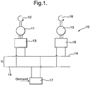
- Figure 1 provides a schematic illustration of a typical electrical power generation system 10 in which a first electrical power generator 11 is typically driven by a turbine 12 with a voltage controller 13 in order to maintain a voltage V upon an electrical power distribution system 14, that is to say between respective rails.
- a second electrical power generator 15 again driven by a turbine 16 provides electrical current to the arrangement 14 through an electrical current controller 16.
- the turbines 12, 16 may be the same prime mover or different turbines or engines within an arrangement.
- a number of electrical power generators 11, 15 are provided with only one generator 11 operating with voltage control whilst the other generators 15 operate with electrical current control.
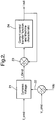
- FIG. 2 provides a schematic illustration of dynamic voltage control of the electrical current controller in accordance with aspects of the present invention.
- electrical current command I_cmd is presented to another electrical current controller 21.
- the controller 21 also receives an indication of operational voltage margin 22 determined by a comparison of the desired voltage V_cmd and an operational voltage Vdc determined by a voltage sensor positioned between the rails of the arrangement 14 ( figure 1 ).
- the controller 21 will act dependent upon the operational voltage margin 22 as indicted.
- the controller 21 in such circumstances will provide a necessary electrical current demand I_Dmd to provide support for the desired voltage within the electrical distribution system.
- V_cmd and Vdc will be substantially the same and therefore there will be no operational margin and therefore the controller 21 will act in accordance with previous arrangements, that is to say the electrical current maintenance will result in the electrical current demand I_Dmd presented will be substantially the same as I_cmd for the conventional electrical current controller as described above with regard to controller 16.
- the controller 21 will act to reconfigure its associated electrical power generator in order to increase the electrical current to I_Dmd and, as such, the input to the electrical power distribution system.
- the desired electrical voltage value may be in the order to 540V for example and therefore if the operational voltage determined by the voltage sensor is also 540V then clearly the system is stable and operating in accordance with acceptable function. In such a steady state the operational voltage margin will be zero, that is to say the voltage error will be zero and the electrical current demand I_Dmd in such circumstances will equal the input electrical current command I_cmd. Thus the system operates in accordance with prior known normal constant electrical current control regimes.
- the operational voltage margin 22 may become large such that a controller 21 as indicted reconfigures its associated electrical generator in order to target electrical current demand, that is to say to add or subtract electrical current in part to support the overall electrical distribution system and therefore stabilise the electrical distribution system by slowing down any rate of change with regard to operational voltage margin or error.
- additional electrical current is provided to support the voltage control stabilisation regime with respect to the first electrical power generator and its associated voltage controller.
- the electrical current demand I_Dmd is presented to a controller 23 which acts in a similar fashion to that as described above with regard to controller 6 in the Prior Art figure to compare the electrical current output Iout to the electrical current input to the controller 23.
- this electrical current input is designated I_Dmd but when the operational voltage margin is zero or below a threshold value the electrical current demand I_Dmd equals steady state electrical current command I_cmd and therefore the system operates in accordance with previous practice.
- the electrical current in such circumstances enters the electrical distribution system and in such circumstances a generator 24 is configured such that Iout equals I_cmd.
- the controller 21 will designate a necessary electrical current demand I_Dmd which again through the controller 23 will act upon the electrical power generator 24 to ensure that the electrical current output (Iout) provided by the appropriately configured electrical current generator 24 is at the necessary current I_Dmd to provide support for the voltage maintenance objectives of the first electrical power generator with its associated voltage controller.
- the additional electrical current provided by the second electrical generator in terms of the electrical current Iout will as indicated above act to supplement the effects of the voltage control on the first electrical power generator such that gradually the necessary additional electrical current will reduce as the voltage returns to a stable level at a desired voltage value.
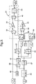
- the electrical current controller in accordance with aspects of the present invention acts upon the basis of an integrator as depicted in figure 3 .
- the input to the integrator is defined as the operational voltage margin or error between the desired electrical current demand I_Dmd and the targeted electrical current command I_cmd in order to supplement the voltage control.
- This voltage margin is output from the controller in order to reconfigure as indicated the second electrical power generator to provide the desired electrical current additionally above that for the stable electrical current operation.
- the electrical current demands will generally be integrated to zero so that the associated second electrical generator will operate with the electrical current control output and the desired electrical current for steady state operation.
- the input to the integrator electrical current controller is also superimposed by a voltage error or margin proportional to the voltage error between the desired voltage for the electrical distribution system and the actually determined electrical voltage system found through a voltage sensor across the electrical power distribution system.
- the output from the electrical current controller provides a necessary target electrical current demand which can be boosted either up or down dynamically by the respective operational voltage margin or errors.
- the electrical current controller acts as a slave to the voltage controller.
- the electrical current command I_cmd is presented to the controller depicted by broken line box 31.
- this electrical current command I_cmd is compared with the electrical current of the system with a comparator 32 which then acts through an appropriate gain 33 and integrator 34 to maintain the desired electrical demand I_Dmd.
- I_cmd As indicated with the voltage within an acceptable threshold range I_cmd will be maintained by the electrical current controller 31 such that I_Dmd output from the controller is the same as I_cmd.
- the voltage controller for the first electrical power generator voltage demand Vdc first is appropriately filtered through a filter 35 and then the signal is used in a comparator 36 to compare the operational voltage Vdc with the desired voltage, for example as illustrated at 540V.
- the determined operational voltage after filtering at filter 35 is also presented to a signal differentiator 37 such that a logic integrator can be created through respective paths to switches 38, 39 based on the rate of change of Vdc.
- a comparator 36 for operational voltage Vdc to determine whether it is substantially equivalent to the desired voltage 40 is used and if equivalent then a zero value is presented to a band filter 41.
- the band filter 41 presents signals dependent upon the differentials provided by the comparator 36 to respective signal limiters 42, 43.
- signal limiter 42 it will be noted that the differential between the operational voltage Vdc and the desired voltage 40 is such that the operational voltage is greater than expected.
- the signal limiter 43 the converse is true in that the operational voltage determined by the voltage sensor is lower than the desired voltage 40.
- the respective signal limiters 42, 43 in such circumstances provide input signals to switches 38, 39 respectively.
- Other switch 38, 39 inputs are provided by the signal differentiator 37 which receives the operational voltage value after appropriate filtering by filter 35 to determined whether the voltage is increasing or decreasing relative to the desired voltage value.
- the switches 38, 39 provide respective inputs to a summation block 44 which then provides a signal to an amplifier 45 which in turn provides an electrical signal to a summation block 46 within the integrated current controller 31 as described above.
- the effect in such circumstances will be to provide a signal to the integrator 34 resulting in additional electrical current being provided which comprises the base electrical current plus or minus the necessary electrical current to maintain and stabilise the electric distribution system to achieve a desired voltage value or marginal level.
- an effective threshold must be provided prior to triggering of the current control of the second electrical power generator in accordance with aspects of the present invention. Such a threshold level is required to avoid continuous utilisation of the electrical current controller rather than the voltage controller of the first electrical power generator in accordance with previous practice. It will be appreciated that the first electrical power generator with its appropriate voltage control will have a system designed level of capability with regard to stabilising voltage within the electrical power distribution system. Utilisation of a slave electrical current control for second electrical power generators is used for dynamic support rather than continuous control.
- a threshold of at least + 5V is utilised through a dead band filter 41 as described above.
- the electrical current demand can be boosted upwards only if the voltage is 5V lower than the rated or desired electrical voltage value and is still dropping, that is to say dv/dt is less than zero.
- the electrical current demand can be boosted downwards only if the voltage is 5V higher than the desired or rated electrical voltage and that the operational voltage is still rising, that is to say dv/dt is greater than zero.
- the controller only contributes positively to reducing dynamic voltage errors and does not try to fight and is not in conflict with the voltage controller for the first electrical power generator.
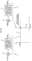
- FIG. 4 provides graphic illustrations of the respective system voltage responses ( figure 4a ), current from the generator controlling the voltage ( figure 4b ) and current from the generator under current control ( figure 4c ).
- the left hand trace shows system dynamics without a dynamic voltage boosting feature for electrical current control of the second generator in accordance with aspects of the present invention.
- the system voltage drops below 520V and rises above 560V respectively during dynamic switching of the load as described above.
- the traces depicted on the right hand side of figure 4 show the results of the same operational conditions with a dynamic boosting electrical current control of the second generator in accordance with aspects of the present invention.
- the transient voltage has reduced by more than 10V by introducing the additional electrical current in accordance with aspects of the present invention.
- the dynamic voltage boosting achieved by the additional electrical current provides an over voltage protection function which is built in automatically to the electrical power distribution arrangement.
- the voltage boosting function with respect to the electrical current controller will boost the electrical current demand to the right level and maintain the system voltage to the edge of the voltage dead band set for activation of this function as described above. Additionally, such an approach avoids occurrence of under voltages should the load level be higher than the electrical current demand assuming that the reserve power rating for the second electrical generator is sufficient to cover the load demand requirements.
- the electrical current demand is boosted to levels required in order to maintain a voltage within normal operational ranges for the electrical distribution system. This will enable an electrical distribution system to remain operational without interruptions.
- the voltage control by the first electrical generator under voltage control will be relatively highly oscillatory with generally high levels of overshoot. If gains from such a voltage controller are not tuned properly then the system may become unstable.
- the voltage control level in the electrical distribution and generation system is controlled by utilisation of electrical current controllers in accordance with aspects of the present invention. In such circumstances the system is more stable with only a small overshoot resulting in a more stable control technique than prior normal voltage control regimes.
- aspects of the present invention may be utilised with regard to a wide range of electrical power distribution networks where it is likely that the generators will operate in parallel and with some electrical generators operating under electrical current control. As illustrated above this may have particular applicability with regard to electrical power generators utilised in aircraft through electrical generators associated with gas turbines although other electrical distribution systems may also be utilised.
Landscapes
- Engineering & Computer Science (AREA)
- Power Engineering (AREA)
- Control Of Eletrric Generators (AREA)
Claims (14)
- Verfahren für den Betrieb eines elektrischen Generatorsystems (10), umfassend einen ersten elektrischen Generator (11), einen Spannungsregler (13), einen zweiten elektrischen Generator (15, 24), einen Stromregler (16) und eine gemeinsame elektrische Leistungsverteilungsanordnung (14), wobei der erste elektrische Generator (11) und der zweite elektrische Generator (15, 24) mit der gemeinsamen elektrischen Leistungsverteilungsanordnung (14) gekoppelt sind, wobei das Verfahren folgendes umfasst:a) Bestimmen eines Betriebsspannungswertes (Vdc) für die gemeinsame elektrische Leistungsverteilungsanordnung (14);b) Vergleichen des Betriebsspannungswertes (Vdc) mit einem gewünschten Spannungswert (V-cmd), um eine Betriebsspannungsspanne (22) zu bestimmen;c) Verwenden des Spannungsreglers (13), um den ersten elektrischen Generator (11) so zu gestalten, dass der gewünschte Spannungswert (V-cmd) in der gemeinsamen elektrischen Leistungsverteilungsanordnung (14) bereitgestellt und im Wesentlichen aufrechterhalten wird; undd) Vergleichen der Betriebsspannungsspanne (22) mit einer vorbestimmten Spannungsspanne, wobei, wenn die Betriebsspannungsspanne (22) die vorbestimmte Spannungsspanne überschreitet, der Stromregler (16, 21) für den zweiten elektrischen Generator (15, 24) zusätzlichen elektrischen Strom (I_Dmd) an die gemeinsame elektrische Leistungsverteilungsanordnung (14) bereitstellt.
- Verfahren nach Anspruch 1, wobei die vorbestimmte Spannungsspanne einstellbar ist.
- Verfahren nach Anspruch 1 oder 2, wobei eine Mehrzahl von vorbestimmten Spannungsspannen vorgesehen ist, um den zusätzlichen elektrischen Strom (I-Dmd) zu verändern, der durch den zweiten elektrischen Generator (15, 24) bereitgestellt wird.
- Verfahren nach einem der Ansprüche 1, 2 oder 3, wobei der zusätzliche elektrische Strom (I-Dmd) stufenweise verändert wird, entweder erhöht oder verringert, bis die Betriebsspannung (Vdc) im Wesentlichen der gewünschten Spannung (V-cmd) entspricht.
- Verfahren nach einem der vorstehenden Ansprüche, wobei eine Mehrzahl zweiter elektrischer Generatoren (15, 24) vorgesehen ist, die hauptsächlich durch einen entsprechenden Stromregler (16, 21) geregelt werden, wobei jeder Stromregler (16, 21) einem Spannungssensor zugeordnet ist.
- Verfahren nach einem der vorstehenden Ansprüche, wobei das Verfahren das Bestimmen umfasst, ob die Betriebsspannungsspanne (22) zunimmt oder abnimmt, wenn sie höher ist als die vorbestimmte Spannungsspanne.
- Elektrisches Generatorsystem, umfassend einen ersten elektrischen Generator (11), einen Spannungsregler (13), einen zweiten elektrischen Generator (15, 24), einen Stromregler (16, 21) und eine gemeinsame elektrische Leistungsverteilungsanordnung (14), wobei der erste elektrische Generator (11) und der zweite elektrische Generator (15, 24) mit der gemeinsamen elektrischen Leistungsverteilungsanordnung (14) gekoppelt sind, wobei der erste elektrische Generator (11) dem Spannungsregler (13) zugeordnet ist, mit einem Spannungssensor zur Bestimmung einer Spannung an der gemeinsamen elektrischen Leistungsverteilungsanordnung (14) und zur Bereitstellung eines Betriebsspannungswertes (Vdc), mit einem Komparator zum Vergleichen des Betriebsspannungswertes (Vdc) mit einem gewünschten Spannungswert (V_cmd), um eine Betriebsspannungsspanne (22) zu bestimmen, wobei der Spannungsregler (13) den ersten elektrischen Generator (11) so gestaltet, dass ein gewünschter Spannungswert (V_cmd) in der gemeinsamen elektrischen Leistungsverteilungsanordnung (14) aufrechterhalten wird, wenn sich der Betriebsspannungswert (Vdc) von dem gewünschten Spannungswert (V_cmd) unterscheidet, wobei das elektrische Generatorsystem dadurch gekennzeichnet ist, dass der zweite elektrische Generator (15, 24) dem Stromregler (16, 21) zugeordnet ist, um einen gewünschten elektrischen Stromwert (I-cmd) in der gemeinsamen elektrischen Leistungsverteilungsanordnung (14) aufrechtzuerhalten, wobei das elektrische Generatorsystem einen zweiten Komparator (21) umfasst, um die Betriebsspannungsspanne (22) mit einer vorbestimmten Spannungsspanne zu vergleichen, wobei, wenn der zweite Komparator (21) bestimmt, dass die Betriebsspannungsspanne (22) die vorbestimmte Spannungsspanne überschreitet, der Stromregler (16, 21) für den zweiten elektrischen Generator (15, 24) so angeordnet ist, dass er zusätzlichen elektrischen Strom (I_Dmd) an die gemeinsame elektrische Leistungsverteilungsanordnung (14) bereitstellt.
- System nach Anspruch 7, wobei die vorbestimmte Spannungsspanne einstellbar ist.
- System nach Anspruch 7 oder 8, wobei eine Mehrzahl vorbestimmter Spannungsspannen vorgesehen ist, um den durch den zweiten elektrischen Generator (15, 24) bereitgestellten zusätzlichen elektrischen Strom (I-Dmd) zu verändern.
- System nach einem der Ansprüche 7 bis 9, wobei der zusätzliche elektrische Strom (I-Dmd) stufenweise verändert wird, entweder erhöht oder verringert, bis die Betriebsspannung (Vdc) im Wesentlichen der gewünschten Spannung (V-cmd) entspricht.
- System nach einem der Ansprüche 7 bis 10, wobei eine Mehrzahl zweiter elektrischer Generatoren (15, 24) vorgesehen ist, die hauptsächlich durch einen entsprechenden Stromregler (16, 21) geregelt werden, wobei jeder Stromregler (16, 21) dem Spannungssensor zugeordnet ist.
- System nach einem der Ansprüche 7 bis 11, wobei der Stromregler (16, 21) Mittel zur Bestimmung aufweist, ob die Betriebsspannungsspanne (22) zunimmt oder abnimmt.
- Gasturbinenmotor, der ein elektrisches Generatorsystem nach einem der Ansprüche 7 bis 12 inkorporiert.
- Luftfahrzeug, das ein elektrisches Generatorsystem nach einem der Ansprüche 7 bis 12 inkorporiert.
Applications Claiming Priority (1)
| Application Number | Priority Date | Filing Date | Title |
|---|---|---|---|
| GB0806491A GB0806491D0 (en) | 2008-04-10 | 2008-04-10 | A method and system for electrical power generation |
Publications (3)
| Publication Number | Publication Date |
|---|---|
| EP2110945A2 EP2110945A2 (de) | 2009-10-21 |
| EP2110945A3 EP2110945A3 (de) | 2017-12-27 |
| EP2110945B1 true EP2110945B1 (de) | 2018-12-05 |
Family
ID=39433396
Family Applications (1)
| Application Number | Title | Priority Date | Filing Date |
|---|---|---|---|
| EP09250707.8A Ceased EP2110945B1 (de) | 2008-04-10 | 2009-03-12 | Verfahren und System zur Erzeugung elektrischen Stroms |
Country Status (3)
| Country | Link |
|---|---|
| US (1) | US7847431B2 (de) |
| EP (1) | EP2110945B1 (de) |
| GB (1) | GB0806491D0 (de) |
Families Citing this family (7)
| Publication number | Priority date | Publication date | Assignee | Title |
|---|---|---|---|---|
| US8098054B2 (en) * | 2007-10-10 | 2012-01-17 | John Alexander Verschuur | Optimal load controller method and device |
| WO2014137422A1 (en) * | 2013-03-08 | 2014-09-12 | Rolls-Royce North Americantechnologies, Inc. | Aircraft and system for supplying electrical power to an aircraft electrical load |
| CN103441493B (zh) * | 2013-07-23 | 2015-04-08 | 广东电网公司电力调度控制中心 | 电网电气分区负荷侧关键断面的自动选择方法 |
| CN103475027B (zh) * | 2013-09-22 | 2015-05-27 | 国家电网公司 | 风电集中接入时风场与枢纽站时间序列协调控制的方法 |
| KR101947858B1 (ko) * | 2015-11-26 | 2019-04-23 | 현대자동차주식회사 | 컨버터 제어방법 및 시스템 |
| US10615685B2 (en) * | 2016-03-21 | 2020-04-07 | Intel Corporation | Deriving power output from an energy harvester |
| US10491147B2 (en) * | 2017-11-29 | 2019-11-26 | Ford Global Technologies, Llc | Dual alternator vehicle power management |
Family Cites Families (9)
| Publication number | Priority date | Publication date | Assignee | Title |
|---|---|---|---|---|
| US4044296A (en) * | 1976-01-14 | 1977-08-23 | Sundstrand Corporation | Electronic voltage regulator for three-phase generators |
| US4222000A (en) * | 1977-07-15 | 1980-09-09 | Lucas Industries Limited | Battery heating system |
| JPS60237870A (ja) * | 1984-05-10 | 1985-11-26 | Nec Corp | モ−タ制御回路 |
| US4829228A (en) * | 1988-05-06 | 1989-05-09 | General Motors Corporation | Dual generator electrical system |
| DE69521287T2 (de) * | 1995-03-24 | 2002-05-02 | Co.Ri.M.Me. Consorzio Per La Ricerca Sulla Microelettronica Nel Mezzogiorno, Catania | Schaltungsanordnung zur Erzeugung einer Referenzspannung und Detektion eines Versorgungsspannungsabfalls und zugehöriges Verfahren |
| EP2083498B1 (de) * | 2000-01-28 | 2010-12-08 | Cummins Generator Technologies Limited | Wechselstromerzeugungssystem |
| US6777822B1 (en) * | 2003-04-01 | 2004-08-17 | Hamilton Sundstrand Corporation | Control system for an auxiliary power unit |
| GB0519019D0 (en) * | 2005-09-17 | 2005-10-26 | Rolls Royce Plc | Electrical power stabilisation |
| GB2435529B (en) | 2006-02-23 | 2008-06-18 | Rolls Royce Plc | A generator control arrangement |
-
2008
- 2008-04-10 GB GB0806491A patent/GB0806491D0/en not_active Ceased
-
2009
- 2009-03-12 EP EP09250707.8A patent/EP2110945B1/de not_active Ceased
- 2009-03-16 US US12/382,391 patent/US7847431B2/en active Active
Non-Patent Citations (1)
| Title |
|---|
| None * |
Also Published As
| Publication number | Publication date |
|---|---|
| US7847431B2 (en) | 2010-12-07 |
| EP2110945A2 (de) | 2009-10-21 |
| EP2110945A3 (de) | 2017-12-27 |
| US20100038969A1 (en) | 2010-02-18 |
| GB0806491D0 (en) | 2008-05-14 |
Similar Documents
| Publication | Publication Date | Title |
|---|---|---|
| EP2110945B1 (de) | Verfahren und System zur Erzeugung elektrischen Stroms | |
| US9628010B2 (en) | Power distribution systems comprising variable frequency AC generator | |
| CA2882057C (en) | Systems and methods for the control and operation of a parallel motor controller architecture | |
| DK2113980T3 (en) | A method of operating a wind power installation | |
| US9941701B2 (en) | Photovoltaic voltage regulation | |
| US11520362B2 (en) | Control for a target common bus voltage | |
| CN100550572C (zh) | 稳定化电力供给系统及其运用方法、以及电力稳定供给的运用工序 | |
| CA3062472C (en) | Method for operating a wind farm | |
| JP6824630B2 (ja) | 無停電電源システムを制御する方法、ソフトウェアパッケージおよび無停電電源システム | |
| US12081031B2 (en) | Method for stabilizing the DC voltage in a DC grid, and DC-to-DC converter for connecting a PV generator to a DC grid | |
| KR101967127B1 (ko) | 직류 전력망 전압 제어 방법 | |
| CA3109161A1 (en) | Method of feeding electric power by means of a wind energy system | |
| JP2011067078A (ja) | 電源システム制御方法及び電源システム制御装置 | |
| JP5336244B2 (ja) | 可変速度発電機を作動させることに関連するシステム及び方法 | |
| US20220037889A1 (en) | Method for feeding in electrical power by means of a wind power installation | |
| CN110350574B (zh) | 一种海上风电经柔直接入系统的紧急功率控制方法和系统 | |
| WO2021214851A1 (ja) | 電源システム | |
| US11394314B2 (en) | Control method of a DC/AC converter | |
| US11518538B2 (en) | Control for a target common bus voltage | |
| US8154260B2 (en) | Generating system | |
| EP3182546B1 (de) | Stromerzeugungssystem einer multi-converter-windturbine und steuerungsverfahren dafür | |
| US12368174B2 (en) | Fuel cell power plant control to prevent reactant starvation during islanded mode of operation | |
| JP6853225B2 (ja) | 発電設備の運転方法 | |
| US12237681B2 (en) | Microgrid startup method and startup program | |
| CN121417120B (zh) | 电电混合船舶直流综合电力系统全工况并联组网控制方法 |
Legal Events
| Date | Code | Title | Description |
|---|---|---|---|
| PUAI | Public reference made under article 153(3) epc to a published international application that has entered the european phase |
Free format text: ORIGINAL CODE: 0009012 |
|
| AK | Designated contracting states |
Kind code of ref document: A2 Designated state(s): AT BE BG CH CY CZ DE DK EE ES FI FR GB GR HR HU IE IS IT LI LT LU LV MC MK MT NL NO PL PT RO SE SI SK TR |
|
| AX | Request for extension of the european patent |
Extension state: AL BA RS |
|
| RAP1 | Party data changed (applicant data changed or rights of an application transferred) |
Owner name: ROLLS-ROYCE PLC |
|
| PUAL | Search report despatched |
Free format text: ORIGINAL CODE: 0009013 |
|
| AK | Designated contracting states |
Kind code of ref document: A3 Designated state(s): AT BE BG CH CY CZ DE DK EE ES FI FR GB GR HR HU IE IS IT LI LT LU LV MC MK MT NL NO PL PT RO SE SI SK TR |
|
| AX | Request for extension of the european patent |
Extension state: AL BA RS |
|
| RIC1 | Information provided on ipc code assigned before grant |
Ipc: H02P 9/10 20060101AFI20171120BHEP |
|
| STAA | Information on the status of an ep patent application or granted ep patent |
Free format text: STATUS: REQUEST FOR EXAMINATION WAS MADE |
|
| 17P | Request for examination filed |
Effective date: 20180516 |
|
| RIN1 | Information on inventor provided before grant (corrected) |
Inventor name: TRAINER, DAVID REGINALD Inventor name: LONG, STEPHEN ANDREW Inventor name: HU, LIHUA |
|
| GRAP | Despatch of communication of intention to grant a patent |
Free format text: ORIGINAL CODE: EPIDOSNIGR1 |
|
| STAA | Information on the status of an ep patent application or granted ep patent |
Free format text: STATUS: GRANT OF PATENT IS INTENDED |
|
| INTG | Intention to grant announced |
Effective date: 20180712 |
|
| AKX | Designation fees paid |
Designated state(s): DE FR GB |
|
| GRAS | Grant fee paid |
Free format text: ORIGINAL CODE: EPIDOSNIGR3 |
|
| GRAA | (expected) grant |
Free format text: ORIGINAL CODE: 0009210 |
|
| GRAA | (expected) grant |
Free format text: ORIGINAL CODE: 0009210 |
|
| STAA | Information on the status of an ep patent application or granted ep patent |
Free format text: STATUS: THE PATENT HAS BEEN GRANTED |
|
| AK | Designated contracting states |
Kind code of ref document: B1 Designated state(s): DE FR GB |
|
| REG | Reference to a national code |
Ref country code: GB Ref legal event code: FG4D |
|
| REG | Reference to a national code |
Ref country code: DE Ref legal event code: R096 Ref document number: 602009056003 Country of ref document: DE |
|
| PGFP | Annual fee paid to national office [announced via postgrant information from national office to epo] |
Ref country code: DE Payment date: 20190327 Year of fee payment: 11 Ref country code: FR Payment date: 20190325 Year of fee payment: 11 |
|
| REG | Reference to a national code |
Ref country code: DE Ref legal event code: R097 Ref document number: 602009056003 Country of ref document: DE |
|
| PLBE | No opposition filed within time limit |
Free format text: ORIGINAL CODE: 0009261 |
|
| STAA | Information on the status of an ep patent application or granted ep patent |
Free format text: STATUS: NO OPPOSITION FILED WITHIN TIME LIMIT |
|
| PGFP | Annual fee paid to national office [announced via postgrant information from national office to epo] |
Ref country code: GB Payment date: 20190404 Year of fee payment: 11 |
|
| 26N | No opposition filed |
Effective date: 20190906 |
|
| REG | Reference to a national code |
Ref country code: DE Ref legal event code: R119 Ref document number: 602009056003 Country of ref document: DE |
|
| PG25 | Lapsed in a contracting state [announced via postgrant information from national office to epo] |
Ref country code: DE Free format text: LAPSE BECAUSE OF NON-PAYMENT OF DUE FEES Effective date: 20201001 Ref country code: FR Free format text: LAPSE BECAUSE OF NON-PAYMENT OF DUE FEES Effective date: 20200331 |
|
| GBPC | Gb: european patent ceased through non-payment of renewal fee |
Effective date: 20200312 |
|
| PG25 | Lapsed in a contracting state [announced via postgrant information from national office to epo] |
Ref country code: GB Free format text: LAPSE BECAUSE OF NON-PAYMENT OF DUE FEES Effective date: 20200312 |