EP2110962A1 - Schlitz- und Stabantennas in tragbrem Funkkummunikationsgerät der aufschibaren art - Google Patents
Schlitz- und Stabantennas in tragbrem Funkkummunikationsgerät der aufschibaren art Download PDFInfo
- Publication number
- EP2110962A1 EP2110962A1 EP08103599A EP08103599A EP2110962A1 EP 2110962 A1 EP2110962 A1 EP 2110962A1 EP 08103599 A EP08103599 A EP 08103599A EP 08103599 A EP08103599 A EP 08103599A EP 2110962 A1 EP2110962 A1 EP 2110962A1
- Authority
- EP
- European Patent Office
- Prior art keywords
- slider part
- radio communication
- communication device
- slider
- portable radio
- Prior art date
- Legal status (The legal status is an assumption and is not a legal conclusion. Google has not performed a legal analysis and makes no representation as to the accuracy of the status listed.)
- Withdrawn
Links
- 238000000034 method Methods 0.000 description 2
- 230000002860 competitive effect Effects 0.000 description 1
- 239000002184 metal Substances 0.000 description 1
Images

Classifications
-
- H—ELECTRICITY
- H01—ELECTRIC ELEMENTS
- H01Q—ANTENNAS, i.e. RADIO AERIALS
- H01Q1/00—Details of, or arrangements associated with, antennas
- H01Q1/12—Supports; Mounting means
- H01Q1/22—Supports; Mounting means by structural association with other equipment or articles
- H01Q1/24—Supports; Mounting means by structural association with other equipment or articles with receiving set
- H01Q1/241—Supports; Mounting means by structural association with other equipment or articles with receiving set used in mobile communications, e.g. GSM
- H01Q1/242—Supports; Mounting means by structural association with other equipment or articles with receiving set used in mobile communications, e.g. GSM specially adapted for hand-held use
- H01Q1/243—Supports; Mounting means by structural association with other equipment or articles with receiving set used in mobile communications, e.g. GSM specially adapted for hand-held use with built-in antennas
-
- H—ELECTRICITY
- H01—ELECTRIC ELEMENTS
- H01Q—ANTENNAS, i.e. RADIO AERIALS
- H01Q13/00—Waveguide horns or mouths; Slot antennas; Leaky-waveguide antennas; Equivalent structures causing radiation along the transmission path of a guided wave
- H01Q13/08—Radiating ends of two-conductor microwave transmission lines, e.g. of coaxial lines, of microstrip lines
- H01Q13/085—Slot-line radiating ends
-
- H—ELECTRICITY
- H01—ELECTRIC ELEMENTS
- H01Q—ANTENNAS, i.e. RADIO AERIALS
- H01Q21/00—Antenna arrays or systems
- H01Q21/28—Combinations of substantially independent non-interacting antenna units or systems
-
- H—ELECTRICITY
- H01—ELECTRIC ELEMENTS
- H01Q—ANTENNAS, i.e. RADIO AERIALS
- H01Q9/00—Electrically-short antennas having dimensions not more than twice the operating wavelength and consisting of conductive active radiating elements
- H01Q9/04—Resonant antennas
- H01Q9/16—Resonant antennas with feed intermediate between the extremities of the antenna, e.g. centre-fed dipole
-
- H—ELECTRICITY
- H04—ELECTRIC COMMUNICATION TECHNIQUE
- H04M—TELEPHONIC COMMUNICATION
- H04M1/00—Substation equipment, e.g. for use by subscribers
- H04M1/02—Constructional features of telephone sets
- H04M1/0202—Portable telephone sets, e.g. cordless phones, mobile phones or bar type handsets
- H04M1/0206—Portable telephones comprising a plurality of mechanically joined movable body parts, e.g. hinged housings
- H04M1/0208—Portable telephones comprising a plurality of mechanically joined movable body parts, e.g. hinged housings characterized by the relative motions of the body parts
- H04M1/0235—Slidable or telescopic telephones, i.e. with a relative translation movement of the body parts; Telephones using a combination of translation and other relative motions of the body parts
- H04M1/0237—Sliding mechanism with one degree of freedom
Definitions
- the present invention relates generally to antennas, and particularly to an antenna device in a portable radio communication device.
- An object of the present invention is thus to provide an antenna device in a portable radio communication device which efficiently utilizes available space therein.
- a portable radio communication device comprising a first slider part and a second slider part and an antenna device, wherein the first slider part has an inner side facing the second slider part and an outer side facing away from the second slider part, the second slider part has an inner side facing the first slider part and an outer side facing away from the first slider part, and the first slider part and the second slider part are configured to be slidable parallel to each other and to be temporarily fixed positioned in a first closed position and a second open position, wherein the inner side of the first slider part is covered by the second slider part and the inner side of the second slider part is covered by the first slider part in the closed position and the inner side of the first slider part is partly covered by the second slider part and the inner side of the second slider part is partly covered by the first slider part in the open position, wherein the antenna device comprises a radiating element which is a piece of the portable radio communication device also having another function for the portable radio communication device, available space is efficiently utilized.
- the antenna device is naturally protected in standby mode and displayed in active mode, which provides for improved antenna characteristics at the same time allowing a large area of the portable radio communication device to be used as radiating element.
- the decorative plate is preferably provided with an open ended slot tuned to a predefined frequency band, to improve antenna characteristics. Also, by preferably providing a feeding point arranged on a first side of the slot, and a grounding point arranged on a second side of the slot opposite the feeding point, further improvement is achieved.
- a feeding point is preferably positioning on the slider rail in a predefined position to match the radiating element.
- the feeding point is preferably fed through a sliding spring loaded contact, or alternatively through a flexible cable connection.
- the antenna characteristics is preferably boosted by configuring the radiating element to parasitically couple to a printed wiring board of at least one of the first slider part and the second slider part.
- a portable radio communication device according to a first embodiment of the present invention will now be described with reference to Figs. 1-2 .
- the portable radio communication device comprises a first slider part 1 and a second slider part 2 and an antenna device.
- the first slider part 1 has an inner side facing the second slider part 2 and an outer side facing away from the second slider part 2, and correspondingly the second slider part 2 has an inner side facing the first slider part 1 and an outer side facing away from the first slider part 1.
- the first slider part 1 and the second slider part 2 are configured to be slidable parallel to each other and to be temporarily fixed positioned in a first closed position and a second open position, wherein the inner side of the first slider part 1 is covered by the second slider part 2 and the inner side of the second slider part 2 is covered by the first slider part 1 in the closed position and the inner side of the first slider part 1 is partly covered by the second slider part 2 and the inner side of the second slider part 2 is partly covered by the first slider part 1 in the open position.
- the first slider part 1 comprises a display and possibly a key pad
- the second slider part 2 comprises RF circuitry, processing capabilities, a possible camera, and alternatively the key pad.
- the antenna device comprises a radiating element 8 which is a piece of the portable radio communication device also having another function for the portable radio communication device.
- At least one of the first slider part 1 and the second slider part 2 comprises a decorative plate 8 covering a major portion of the inner side that is revealed when the first slider part 1 and the second slider 2 are in the open position, which decorative plate 8 also is the radiating element 8.
- the most suitable position for the radiating element 8 is in the first slider part 1, since this part is facing away from a user speaking in the slider mobile phone, and further the second slider part 2 many times have a key pad, instead of a decorative plate, revealed in the open position.
- the decorative plate 8 is provided with an open ended slot 9 tuned to a predefined frequency band or bands, such as BT, WLAN (2.4 GHz) and WiMax (3.5 GHz).
- a feeding point 10 is preferably arranged on a first side of the slot 9, and a grounding point 11 is preferably arranged on a second side of the slot 9 opposite the feeding point 10. Further, the feeding and grounding points 10, 11 are preferably arranged at a distance from the end of the slot 9, wherein the distance is selected to match the radiating element 8.
- the radiating element 8 is preferably configured to parasitically couple to a printed wiring board of at least one of the first slider part 1 and the second slider part 2. This is particularly useful in closed position, when the radiating element 8 is boxed in between the first slider part 1 and the second slider part 2.
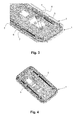
- a portable radio communication device according to a second embodiment of the present invention will now be described with reference to Figs 3-4 .
- the portable radio communication device comprises a first slider part 1 and a second slider part 2 and an antenna device.
- the first slider part 1 has an inner side facing the second slider part 2 and an outer side facing away from the second slider part 2, and correspondingly the second slider part 2 has an inner side facing the first slider part 1 and an outer side facing away from the first slider part 1.
- the first slider part 1 and the second slider part 2 are configured to be slidable parallel to each other and to be temporarily fixed positioned in a first closed position and a second open position, wherein the inner side of the first slider part 1 is covered by the second slider part 2 and the inner side of the second slider part 2 is covered by the first slider part 1 in the closed position and the inner side of the first slider part 1 is partly covered by the second slider part 2 and the inner side of the second slider part 2 is partly covered by the first slider part 1 in the open position.
- the first slider part 1 comprises a display and possibly a key pad
- the second slider part 2 comprises RF circuitry, processing capabilities, a possible camera, and alternatively the key pad.
- the antenna device comprises a radiating element 5 which is a piece of the portable radio communication device also having another function for the portable radio communication device.
- the portable radio communication device comprises at least one slider rail 5, usually two parallel slider rails 5, along which the first slider part 1 and the second slider part 2 slide between the open and closed positions, which slider rail 5 is also the radiating element 5.
- all slider rails could be used as radiating elements 5, for separate frequency bands, for diversity function, or a combination of separate frequency bands and diversity function.
- a feeding point for the antenna device is preferably positioned on the slider rail 5 to match the radiating element 5.
- the antenna device can be optimized for either open position or closed position of the portable radio communication device.
- matching, as well as tuning to some degree, of the radiating element can be adjusted by providing more than one feed point to the slider rail, and the electronic length of the radiating element could also be adjusted by providing multiple grounding points to the slider rail.
- the radiating element is preferably configured to parasitically couple to a printed wiring board of at least one of the first slider part and the second slider part, to boost antenna characteristics, particularly in the closed position.
- a portable radio communication device according to a third embodiment of the present invention will now be described.
- the third embodiment is similar to the first embodiment described above, apart from the following.
- the decorative plate is provided with a slot, for slot feeding a printed wiring board of the first slider part, and/or the second slider part, which thereby will function as a slot fed stacked patch antenna.
- other conductive portions of the portable radio communication device are preferably alternatively, or additionally, utilized for slot feeding of the printed wiring boards.
- An antenna device according to the first, second, and third embodiments of the present invention, respectively, as described above, can further be combined.
- the portable radio communication device comprises a decorative plate and one or more slider rails, all such parts can be utilized as radiating elements, for separate frequency bands, for diversity function, or a combination of separate frequency bands and diversity function.
- conductive features that can serve as an antenna is e.g. handset casing, battery, board level shielding boxes, logo plates, buttons, switches, speaker grilles, bezels, decorative trims, touch screen input pen, flat-panel speaker, decorative metal covers, logo plates, slider actuators, and slider back plates.
Landscapes
- Engineering & Computer Science (AREA)
- Computer Networks & Wireless Communication (AREA)
- Signal Processing (AREA)
- Telephone Set Structure (AREA)
- Support Of Aerials (AREA)
Priority Applications (3)
| Application Number | Priority Date | Filing Date | Title |
|---|---|---|---|
| EP08103599A EP2110962A1 (de) | 2008-04-17 | 2008-04-17 | Schlitz- und Stabantennas in tragbrem Funkkummunikationsgerät der aufschibaren art |
| TW98112607A TW201004043A (en) | 2008-04-17 | 2009-04-16 | An antenna device and a portable radio communication device comprising such an antenna device |
| CNA2009102039927A CN101562645A (zh) | 2008-04-17 | 2009-04-17 | 天线装置和包括该天线装置的便携式无线通信装置 |
Applications Claiming Priority (1)
| Application Number | Priority Date | Filing Date | Title |
|---|---|---|---|
| EP08103599A EP2110962A1 (de) | 2008-04-17 | 2008-04-17 | Schlitz- und Stabantennas in tragbrem Funkkummunikationsgerät der aufschibaren art |
Publications (1)
| Publication Number | Publication Date |
|---|---|
| EP2110962A1 true EP2110962A1 (de) | 2009-10-21 |
Family
ID=39831946
Family Applications (1)
| Application Number | Title | Priority Date | Filing Date |
|---|---|---|---|
| EP08103599A Withdrawn EP2110962A1 (de) | 2008-04-17 | 2008-04-17 | Schlitz- und Stabantennas in tragbrem Funkkummunikationsgerät der aufschibaren art |
Country Status (3)
| Country | Link |
|---|---|
| EP (1) | EP2110962A1 (de) |
| CN (1) | CN101562645A (de) |
| TW (1) | TW201004043A (de) |
Cited By (1)
| Publication number | Priority date | Publication date | Assignee | Title |
|---|---|---|---|---|
| WO2021114356A1 (zh) * | 2019-12-10 | 2021-06-17 | 惠州Tcl移动通信有限公司 | 一种天线调谐方法、装置及存储介质 |
Families Citing this family (1)
| Publication number | Priority date | Publication date | Assignee | Title |
|---|---|---|---|---|
| CN110401011B (zh) * | 2018-04-25 | 2021-07-06 | Oppo广东移动通信有限公司 | 电子设备 |
Citations (6)
| Publication number | Priority date | Publication date | Assignee | Title |
|---|---|---|---|---|
| EP1280226A1 (de) | 2000-04-20 | 2003-01-29 | Mitsubishi Denki Kabushiki Kaisha | Tragbares funkgerät |
| EP1306922A2 (de) | 2001-10-24 | 2003-05-02 | Matsushita Electric Industrial Co., Ltd. | Antennenstruktur, Verfahren zur deren Verwendung und Kommunikationsgerät |
| US20050052329A1 (en) | 2003-09-09 | 2005-03-10 | Sony Corporation | Wireless communication apparatus |
| US20050248492A1 (en) | 2004-02-17 | 2005-11-10 | Samsung Electronics Co., Ltd. | Antenna device for portable wireless terminal |
| DE202007002281U1 (de) | 2007-02-16 | 2007-04-12 | Lumberg Connect Gmbh | Mobiles Kommunikationsgerät |
| WO2007058230A1 (ja) | 2005-11-18 | 2007-05-24 | Nec Corporation | スロットアンテナ及び携帯無線端末 |
-
2008
- 2008-04-17 EP EP08103599A patent/EP2110962A1/de not_active Withdrawn
-
2009
- 2009-04-16 TW TW98112607A patent/TW201004043A/zh unknown
- 2009-04-17 CN CNA2009102039927A patent/CN101562645A/zh active Pending
Patent Citations (6)
| Publication number | Priority date | Publication date | Assignee | Title |
|---|---|---|---|---|
| EP1280226A1 (de) | 2000-04-20 | 2003-01-29 | Mitsubishi Denki Kabushiki Kaisha | Tragbares funkgerät |
| EP1306922A2 (de) | 2001-10-24 | 2003-05-02 | Matsushita Electric Industrial Co., Ltd. | Antennenstruktur, Verfahren zur deren Verwendung und Kommunikationsgerät |
| US20050052329A1 (en) | 2003-09-09 | 2005-03-10 | Sony Corporation | Wireless communication apparatus |
| US20050248492A1 (en) | 2004-02-17 | 2005-11-10 | Samsung Electronics Co., Ltd. | Antenna device for portable wireless terminal |
| WO2007058230A1 (ja) | 2005-11-18 | 2007-05-24 | Nec Corporation | スロットアンテナ及び携帯無線端末 |
| DE202007002281U1 (de) | 2007-02-16 | 2007-04-12 | Lumberg Connect Gmbh | Mobiles Kommunikationsgerät |
Cited By (2)
| Publication number | Priority date | Publication date | Assignee | Title |
|---|---|---|---|---|
| WO2021114356A1 (zh) * | 2019-12-10 | 2021-06-17 | 惠州Tcl移动通信有限公司 | 一种天线调谐方法、装置及存储介质 |
| US11799994B2 (en) | 2019-12-10 | 2023-10-24 | Huizhou Tcl Mobile Communication Co., Ltd. | Antenna tuning method and apparatus, and storage medium |
Also Published As
| Publication number | Publication date |
|---|---|
| TW201004043A (en) | 2010-01-16 |
| CN101562645A (zh) | 2009-10-21 |
Similar Documents
| Publication | Publication Date | Title |
|---|---|---|
| US11038254B2 (en) | Mobile device | |
| EP2467905B1 (de) | Steckverbinder mit eingebetteten antennen | |
| KR101572037B1 (ko) | 이동 단말기 | |
| US8933849B2 (en) | Portable wireless device | |
| US20170005393A1 (en) | Antenna module and mobile device using same | |
| KR102128391B1 (ko) | 금속을 포함하는 케이스 및 그를 구비하는 전자 기기 | |
| US20150295314A1 (en) | Loop antenna having a parasitically coupled element | |
| KR101777606B1 (ko) | 이동 단말기 | |
| KR100733813B1 (ko) | 휴대용 무선단말기의 안테나 장치 | |
| JP2013005431A (ja) | 携帯端末機のアンテナ装置 | |
| CN102110887A (zh) | 倒f天线和手持电子设备 | |
| KR20130022203A (ko) | 휴대용 단말기의 안테나 장치 | |
| KR20110025547A (ko) | 안테나 어셈블리 및 이를 갖는 이동 단말기 | |
| US9455492B2 (en) | Multiband antenna arrangement | |
| US20180115054A1 (en) | Mobile device | |
| US7283098B2 (en) | Antenna apparatus for portable terminal | |
| EP2996198A1 (de) | Breitbandantenne für mobiles system mit metallrückseite | |
| US20160111778A1 (en) | Multiple-Input Multiple-Output Antenna System and Apparatus | |
| US8138979B2 (en) | Portable wireless apparatus | |
| EP2110962A1 (de) | Schlitz- und Stabantennas in tragbrem Funkkummunikationsgerät der aufschibaren art | |
| KR20110102737A (ko) | 이동 단말기 | |
| JP2006148943A (ja) | アンテナ性能の改善のための導電体を有する携帯用無線端末機 | |
| US20150207231A1 (en) | Co-located antennas and an electronic device including the same | |
| KR100872431B1 (ko) | 안테나 및 이를 구비한 이동통신 단말기 | |
| KR101604715B1 (ko) | 휴대 단말기 |
Legal Events
| Date | Code | Title | Description |
|---|---|---|---|
| PUAI | Public reference made under article 153(3) epc to a published international application that has entered the european phase |
Free format text: ORIGINAL CODE: 0009012 |
|
| AK | Designated contracting states |
Kind code of ref document: A1 Designated state(s): AT BE BG CH CY CZ DE DK EE ES FI FR GB GR HR HU IE IS IT LI LT LU LV MC MT NL NO PL PT RO SE SI SK TR |
|
| AX | Request for extension of the european patent |
Extension state: AL BA MK RS |
|
| 17P | Request for examination filed |
Effective date: 20100412 |
|
| 17Q | First examination report despatched |
Effective date: 20100521 |
|
| AKX | Designation fees paid |
Designated state(s): DE |
|
| STAA | Information on the status of an ep patent application or granted ep patent |
Free format text: STATUS: THE APPLICATION IS DEEMED TO BE WITHDRAWN |
|
| 18D | Application deemed to be withdrawn |
Effective date: 20121101 |