EP2111024A1 - Détection de dispositifs et conditions de faute au moyen de caractéristiques U/I ou I/U - Google Patents
Détection de dispositifs et conditions de faute au moyen de caractéristiques U/I ou I/U Download PDFInfo
- Publication number
- EP2111024A1 EP2111024A1 EP08103574A EP08103574A EP2111024A1 EP 2111024 A1 EP2111024 A1 EP 2111024A1 EP 08103574 A EP08103574 A EP 08103574A EP 08103574 A EP08103574 A EP 08103574A EP 2111024 A1 EP2111024 A1 EP 2111024A1
- Authority
- EP
- European Patent Office
- Prior art keywords
- subscriber line
- voltage
- currents
- wires
- line
- Prior art date
- Legal status (The legal status is an assumption and is not a legal conclusion. Google has not performed a legal analysis and makes no representation as to the accuracy of the status listed.)
- Withdrawn
Links
Images


Classifications
-
- H—ELECTRICITY
- H04—ELECTRIC COMMUNICATION TECHNIQUE
- H04M—TELEPHONIC COMMUNICATION
- H04M3/00—Automatic or semi-automatic exchanges
- H04M3/22—Arrangements for supervision, monitoring or testing
- H04M3/26—Arrangements for supervision, monitoring or testing with means for applying test signals or for measuring
- H04M3/28—Automatic routine testing ; Fault testing; Installation testing; Test methods, test equipment or test arrangements therefor
- H04M3/30—Automatic routine testing ; Fault testing; Installation testing; Test methods, test equipment or test arrangements therefor for subscriber's lines, for the local loop
- H04M3/305—Automatic routine testing ; Fault testing; Installation testing; Test methods, test equipment or test arrangements therefor for subscriber's lines, for the local loop testing of physical copper line parameters, e.g. capacitance or resistance
-
- G—PHYSICS
- G01—MEASURING; TESTING
- G01R—MEASURING ELECTRIC VARIABLES; MEASURING MAGNETIC VARIABLES
- G01R31/00—Arrangements for testing electric properties; Arrangements for locating electric faults; Arrangements for electrical testing characterised by what is being tested not provided for elsewhere
- G01R31/26—Testing of individual semiconductor devices
- G01R31/2601—Apparatus or methods therefor
- G01R31/2603—Apparatus or methods therefor for curve tracing of semiconductor characteristics, e.g. on oscilloscope
Definitions
- the invention relates to a test method for measuring the state of a subscriber line with two electrically conductive wires, and for determining one or more characteristics from the measurements and for determining the type of devices connected to the line and for detecting fault conditions on the line by means of the determined characteristics.
- a functioning telephone connection is an important prerequisite for ensuring that telecommunications subscribers can rely on the services and features of a telecommunications network.
- EP 0580893 introduces measuring heads or integrated line test functions offered by suppliers of network technology.
- the copper line is not only connected to terminals (CPE), but also to additional facilities like a passive test termination in the connector box (PPA), splitters and various broadband and narrowband network terminators of different providers, which are often installed by the customers themselves.
- CPE terminals
- PPA connector box
- splitters and various broadband and narrowband network terminators of different providers, which are often installed by the customers themselves.
- the various service providers can not analyze exactly what caused the fault condition, and consequently who is responsible for its repair.
- the integrated measuring technology known in the art described by the patent DE699330455T2 , measures noise voltage, resistors, capacitors and impedances at high voltages on the subscriber lines, wherein, due to the high number of measuring heads, no statement can be made on the prevailing measuring conditions. Customer- and country-specific test methods and parameters are defined for each connected facility.
- This known measuring technology does not provide an inexpensive and accurate analysis of the increasingly complex networks. If, for example, ISDN and xDSL are combined on one copper line, this creates a nonlinear resistor curve as a function of the measuring voltage, which can not easily be captured by the technology known today. Instead, for each connected facility specific measuring processes need to be programmed. Also, newer CPE can not be detected by the measuring methods known today.
- the complex mix of different technologies causes an increasing number of measuring errors and, at present, an exact analysis of a network is hardly possible.
- a measuring head captures voltage/current characteristics (U/I curves), or current/voltage characteristics (I/U curves) for the two wires of the subscriber line.
- Time-variable voltages or currents are applied to both wires of the subscriber line and the resulting voltages or currents are determined and stored in such a way that the temporal relation between voltage and current is maintained.
- the U/I or I/U characteristics are made available for an external evaluation system via an interface of the testing facility.
- Previously determined typical masks or evaluations of vector changes in the resulting curves are used to evaluate the V/I curves and thus to detect fault conditions or the existence and functioning state of a device on the subscriber line.
- Figure 2 to Figure 9 show examples of typical U/I characteristics for different facilities connected to the subscriber line.
- the resistances detected in the test methods known in the art contain no information about the voltage or current that has been used for their determination.
- the invention makes it possible for the network operator to display the curve of resistance as a function of the measuring voltage and thereby obtain the test result.
- the accuracy of the measured values is improved, since nonlinear areas of the U/I curve or areas of saturation of the measuring head can now be reevaluated.
- voltages or currents with a constant slope over time are used as variable voltages or currents. This way charging currents of capacities or inductors can be detected.
- the result are defined U/I characteristics for a subscriber line with a connected CPE and additional facilities. If the characteristics are captured with a constant dU/dt, also facilities behind a capacity on the subscriber line can be seen. This is especially important for the detection of terminal units, since the ringer capacities of newer devices are small and hard to differentiate from the line capacity.
- test method according to the invention can be combined with existing test methods, e.g. with impedance measuring at higher frequencies. This further increases the advantages of the invention, because network operators can combine this method with their specific experiences concerning elements of traditional test methods.
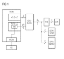
- a PSTN is displayed in Figure 1 , containing an xDSL line card xDSL-LC.
- This line card generates DSL signals which are routed to an xDSL splitter via a pair of wires.
- the splitter combines the DSL signals with the analogue signals of a traditional POTS line card LC, thus creating a mixed signal which is applied to the two-wire copper line SL.
- a PPA with CPE solid line
- an ISDN NTBA or xDSL Splitter dashexing Line
- the POTS line card LC contains a measuring head MK, which applies currents or voltages to the connected wires a/b and measures the resulting voltages and currents.
- the measuring head MK generates U/I or I/U characteristics from the previously measured values and, via an interface MSAN, delivers them to an expert system ES.
- the characteristics are compared with stored characteristic masks which are specific for facilities on the subscriber line and for fault conditions. If the curve lies within one of the stored masks, the facility corresponding to the stored mask, or a fault condition corresponding to another saved mask, can be identified.
- Figure 2 shows the equivalent circuit diagram of an ISDN NTBA, consisting of a combination of Zener diodes and a DC converter DC/DC.
- the U/I characteristic K of Figure 3 shows that in the case of the application of a variable voltage U, a current I flows only when a certain voltage is reached. The current is smaller at higher voltages, since the product of voltage and current is approximately constant, as long as the power supplied to the ISDN NTBA remains constant. If the U/I characteristic lies within in a mask M, the existence of an ISDN NTBA can be concluded.
- Figure 4 is the equivalent circuit diagram of a test termination PPA, consisting of a resistor and a diode.
- Figure 5 shows that the quotient of voltage and current is smaller for positive voltages than for negative voltages, since in the case of a negative voltage, the resistor takes effect due to the diode (as shown in the equivalent circuit 4).
- the presence of a PPA can be concluded from the U/I characteristic.
- Figure 6 is the equivalent circuit diagram of an xDSL splitter, consisting of a resistor, a capacitor and a combination of Zener diodes.
- Figure 7 shows that a voltage ramp with a positive slope generates a different characteristic than a voltage ramp with a negative slope, which is due to the effect of the capacitor.
- the presence of an xDSL splitter can be concluded from the U/I characteristic.
- Figure 8 shows a resistor as the equivalent circuit diagram of a short circuit on the wires a/b.
- Figure 9 displays the U/I characteristic as a straight line, the slope of which allows to identify the existence and the location of a short circuit.
Landscapes
- Engineering & Computer Science (AREA)
- Signal Processing (AREA)
- Monitoring And Testing Of Exchanges (AREA)
Priority Applications (1)
| Application Number | Priority Date | Filing Date | Title |
|---|---|---|---|
| EP08103574A EP2111024A1 (fr) | 2008-04-16 | 2008-04-16 | Détection de dispositifs et conditions de faute au moyen de caractéristiques U/I ou I/U |
Applications Claiming Priority (1)
| Application Number | Priority Date | Filing Date | Title |
|---|---|---|---|
| EP08103574A EP2111024A1 (fr) | 2008-04-16 | 2008-04-16 | Détection de dispositifs et conditions de faute au moyen de caractéristiques U/I ou I/U |
Publications (1)
| Publication Number | Publication Date |
|---|---|
| EP2111024A1 true EP2111024A1 (fr) | 2009-10-21 |
Family
ID=39789840
Family Applications (1)
| Application Number | Title | Priority Date | Filing Date |
|---|---|---|---|
| EP08103574A Withdrawn EP2111024A1 (fr) | 2008-04-16 | 2008-04-16 | Détection de dispositifs et conditions de faute au moyen de caractéristiques U/I ou I/U |
Country Status (1)
| Country | Link |
|---|---|
| EP (1) | EP2111024A1 (fr) |
Cited By (1)
| Publication number | Priority date | Publication date | Assignee | Title |
|---|---|---|---|---|
| CN108054734A (zh) * | 2017-11-22 | 2018-05-18 | 深圳供电局有限公司 | 一种基于故障特征匹配的配网保护方法及系统 |
Citations (6)
| Publication number | Priority date | Publication date | Assignee | Title |
|---|---|---|---|---|
| EP0580947A2 (fr) * | 1992-03-31 | 1994-02-02 | Siemens Aktiengesellschaft | Procédé pour déterminer des grandeurs électriques |
| EP0580893A1 (fr) | 1992-07-31 | 1994-02-02 | Siemens Aktiengesellschaft | Méthode de test pour tester un raccordement d'abonné |
| WO2001063893A2 (fr) * | 2000-02-24 | 2001-08-30 | Teradyne Inc | Procede et appareil de detection des raccordements dans un environnement adsl |
| US20050094785A1 (en) * | 2000-03-03 | 2005-05-05 | Teradyne, Inc. | Technique for estimation of a subscriber line insertion loss |
| EP1729489A1 (fr) * | 2005-05-31 | 2006-12-06 | Infineon Technologies AG | Procédé pour mesurer une propriété capacitive d'une ligne de communication et l'appareil correspondant |
| DE69933045T2 (de) | 1998-11-03 | 2007-04-12 | Teradyne Inc., Boston | Fehlerzustände welche hochgeschwindigkeitsdatendienste beeinträchtigen |
-
2008
- 2008-04-16 EP EP08103574A patent/EP2111024A1/fr not_active Withdrawn
Patent Citations (6)
| Publication number | Priority date | Publication date | Assignee | Title |
|---|---|---|---|---|
| EP0580947A2 (fr) * | 1992-03-31 | 1994-02-02 | Siemens Aktiengesellschaft | Procédé pour déterminer des grandeurs électriques |
| EP0580893A1 (fr) | 1992-07-31 | 1994-02-02 | Siemens Aktiengesellschaft | Méthode de test pour tester un raccordement d'abonné |
| DE69933045T2 (de) | 1998-11-03 | 2007-04-12 | Teradyne Inc., Boston | Fehlerzustände welche hochgeschwindigkeitsdatendienste beeinträchtigen |
| WO2001063893A2 (fr) * | 2000-02-24 | 2001-08-30 | Teradyne Inc | Procede et appareil de detection des raccordements dans un environnement adsl |
| US20050094785A1 (en) * | 2000-03-03 | 2005-05-05 | Teradyne, Inc. | Technique for estimation of a subscriber line insertion loss |
| EP1729489A1 (fr) * | 2005-05-31 | 2006-12-06 | Infineon Technologies AG | Procédé pour mesurer une propriété capacitive d'une ligne de communication et l'appareil correspondant |
Cited By (2)
| Publication number | Priority date | Publication date | Assignee | Title |
|---|---|---|---|---|
| CN108054734A (zh) * | 2017-11-22 | 2018-05-18 | 深圳供电局有限公司 | 一种基于故障特征匹配的配网保护方法及系统 |
| CN108054734B (zh) * | 2017-11-22 | 2019-10-22 | 深圳供电局有限公司 | 一种基于故障特征匹配的配网保护方法及系统 |
Similar Documents
| Publication | Publication Date | Title |
|---|---|---|
| US6975706B1 (en) | Capacitance measurement-based mechanism for locating open telecommunication line fault | |
| US6763108B1 (en) | Apparatus and method for line pair testing and fault diagnostics | |
| US6535580B1 (en) | Signature device for home phoneline network devices | |
| CN103250404B (zh) | 用于确定dsl电信线路的全局线路特性的诊断引擎及其使用方法 | |
| EP0168410B1 (fr) | Unite terminale d'entretien amelioree | |
| CA2377638C (fr) | Lignes telephoniques s'adaptant a la transmission de donnees | |
| US8908752B2 (en) | Line testing | |
| US8339145B2 (en) | Line testing | |
| US7508219B2 (en) | Apparatus and method for measuring loop insertion loss single-endedly | |
| US7076030B2 (en) | Method and system for testing XDSL wiring | |
| US4373121A (en) | Maintenance termination device | |
| EP2111024A1 (fr) | Détection de dispositifs et conditions de faute au moyen de caractéristiques U/I ou I/U | |
| US3660620A (en) | Transmission measurement with a two-component signal | |
| US6169784B1 (en) | Telecommunication line termination test | |
| US9025733B2 (en) | Method and apparatus for line testing | |
| US7302046B2 (en) | Method for the detection of impedances and for the qualification of the telephone lines | |
| US4629835A (en) | Fault isolating apparatus system and method | |
| US8102970B2 (en) | Method and apparatus for line testing | |
| US9225825B2 (en) | Method and apparatus for line testing | |
| US7995490B2 (en) | System and method for identifying a signature of a device, in a communication circuit, utilizing distortion products | |
| WO2002033941A1 (fr) | Procede et dispositif permettant de tester des lignes telephoniques et de donnees dans un systeme de telecommunications | |
| KR101301280B1 (ko) | 다수의 스트랜드들을 포함하는 사용자 연결 케이블으로의 양의 공급 전압의 스위칭온을 확인하기 위한 방법 및 장치 | |
| Noessing et al. | Metallic line testing solution for next generation networks | |
| JP2880006B2 (ja) | Isdn加入者線路測定方法及びその測定装置 | |
| CN100499697C (zh) | 一种测试市话电缆频率响应的方法 |
Legal Events
| Date | Code | Title | Description |
|---|---|---|---|
| PUAI | Public reference made under article 153(3) epc to a published international application that has entered the european phase |
Free format text: ORIGINAL CODE: 0009012 |
|
| AK | Designated contracting states |
Kind code of ref document: A1 Designated state(s): AT BE BG CH CY CZ DE DK EE ES FI FR GB GR HR HU IE IS IT LI LT LU LV MC MT NL NO PL PT RO SE SI SK TR |
|
| AX | Request for extension of the european patent |
Extension state: AL BA MK RS |
|
| AKX | Designation fees paid | ||
| STAA | Information on the status of an ep patent application or granted ep patent |
Free format text: STATUS: THE APPLICATION IS DEEMED TO BE WITHDRAWN |
|
| 18D | Application deemed to be withdrawn |
Effective date: 20100422 |
|
| REG | Reference to a national code |
Ref country code: DE Ref legal event code: 8566 |