EP2111040A2 - Désentrelaceur de données dans un système de décodage de signaux de télévision numérique - Google Patents
Désentrelaceur de données dans un système de décodage de signaux de télévision numérique Download PDFInfo
- Publication number
- EP2111040A2 EP2111040A2 EP09159325A EP09159325A EP2111040A2 EP 2111040 A2 EP2111040 A2 EP 2111040A2 EP 09159325 A EP09159325 A EP 09159325A EP 09159325 A EP09159325 A EP 09159325A EP 2111040 A2 EP2111040 A2 EP 2111040A2
- Authority
- EP
- European Patent Office
- Prior art keywords
- deinterleaving
- data
- interleaved
- selection
- memory
- Prior art date
- Legal status (The legal status is an assumption and is not a legal conclusion. Google has not performed a legal analysis and makes no representation as to the accuracy of the status listed.)
- Withdrawn
Links
- 230000004044 response Effects 0.000 claims abstract description 4
- 230000000737 periodic effect Effects 0.000 claims description 3
- 230000006870 function Effects 0.000 abstract description 31
- 238000000034 method Methods 0.000 description 8
- 230000008569 process Effects 0.000 description 6
- 230000005540 biological transmission Effects 0.000 description 4
- 239000000872 buffer Substances 0.000 description 3
- 238000011084 recovery Methods 0.000 description 3
- 238000004891 communication Methods 0.000 description 2
- 238000010586 diagram Methods 0.000 description 2
- 230000001360 synchronised effect Effects 0.000 description 2
- 230000003044 adaptive effect Effects 0.000 description 1
- 230000008901 benefit Effects 0.000 description 1
- 230000008859 change Effects 0.000 description 1
- 125000004122 cyclic group Chemical group 0.000 description 1
- 238000001514 detection method Methods 0.000 description 1
- 238000005516 engineering process Methods 0.000 description 1
- 238000001914 filtration Methods 0.000 description 1
- 238000012163 sequencing technique Methods 0.000 description 1
- 230000008054 signal transmission Effects 0.000 description 1
Images

Classifications
-
- H—ELECTRICITY
- H03—ELECTRONIC CIRCUITRY
- H03M—CODING; DECODING; CODE CONVERSION IN GENERAL
- H03M13/00—Coding, decoding or code conversion, for error detection or error correction; Coding theory basic assumptions; Coding bounds; Error probability evaluation methods; Channel models; Simulation or testing of codes
- H03M13/27—Coding, decoding or code conversion, for error detection or error correction; Coding theory basic assumptions; Coding bounds; Error probability evaluation methods; Channel models; Simulation or testing of codes using interleaving techniques
- H03M13/2789—Interleaver providing variable interleaving, e.g. variable block sizes
-
- H—ELECTRICITY
- H04—ELECTRIC COMMUNICATION TECHNIQUE
- H04N—PICTORIAL COMMUNICATION, e.g. TELEVISION
- H04N21/00—Selective content distribution, e.g. interactive television or video on demand [VOD]
- H04N21/20—Servers specifically adapted for the distribution of content, e.g. VOD servers; Operations thereof
- H04N21/23—Processing of content or additional data; Elementary server operations; Server middleware
- H04N21/231—Content storage operation, e.g. caching movies for short term storage, replicating data over plural servers, prioritizing data for deletion
- H04N21/2312—Data placement on disk arrays
- H04N21/2315—Data placement on disk arrays using interleaving
-
- H—ELECTRICITY
- H03—ELECTRONIC CIRCUITRY
- H03M—CODING; DECODING; CODE CONVERSION IN GENERAL
- H03M13/00—Coding, decoding or code conversion, for error detection or error correction; Coding theory basic assumptions; Coding bounds; Error probability evaluation methods; Channel models; Simulation or testing of codes
- H03M13/27—Coding, decoding or code conversion, for error detection or error correction; Coding theory basic assumptions; Coding bounds; Error probability evaluation methods; Channel models; Simulation or testing of codes using interleaving techniques
- H03M13/276—Interleaving address generation
-
- H—ELECTRICITY
- H03—ELECTRONIC CIRCUITRY
- H03M—CODING; DECODING; CODE CONVERSION IN GENERAL
- H03M13/00—Coding, decoding or code conversion, for error detection or error correction; Coding theory basic assumptions; Coding bounds; Error probability evaluation methods; Channel models; Simulation or testing of codes
- H03M13/65—Purpose and implementation aspects
- H03M13/6508—Flexibility, adaptability, parametrability and configurability of the implementation
-
- H—ELECTRICITY
- H04—ELECTRIC COMMUNICATION TECHNIQUE
- H04N—PICTORIAL COMMUNICATION, e.g. TELEVISION
- H04N19/00—Methods or arrangements for coding, decoding, compressing or decompressing digital video signals
- H04N19/85—Methods or arrangements for coding, decoding, compressing or decompressing digital video signals using pre-processing or post-processing specially adapted for video compression
-
- H—ELECTRICITY
- H04—ELECTRIC COMMUNICATION TECHNIQUE
- H04N—PICTORIAL COMMUNICATION, e.g. TELEVISION
- H04N21/00—Selective content distribution, e.g. interactive television or video on demand [VOD]
- H04N21/20—Servers specifically adapted for the distribution of content, e.g. VOD servers; Operations thereof
- H04N21/23—Processing of content or additional data; Elementary server operations; Server middleware
- H04N21/238—Interfacing the downstream path of the transmission network, e.g. adapting the transmission rate of a video stream to network bandwidth; Processing of multiplex streams
- H04N21/2383—Channel coding or modulation of digital bit-stream, e.g. QPSK modulation
-
- H—ELECTRICITY
- H04—ELECTRIC COMMUNICATION TECHNIQUE
- H04N—PICTORIAL COMMUNICATION, e.g. TELEVISION
- H04N21/00—Selective content distribution, e.g. interactive television or video on demand [VOD]
- H04N21/40—Client devices specifically adapted for the reception of or interaction with content, e.g. set-top-box [STB]; Operations thereof
- H04N21/41—Structure of client; Structure of client peripherals
- H04N21/426—Internal components of the client ; Characteristics thereof
-
- H—ELECTRICITY
- H04—ELECTRIC COMMUNICATION TECHNIQUE
- H04N—PICTORIAL COMMUNICATION, e.g. TELEVISION
- H04N21/00—Selective content distribution, e.g. interactive television or video on demand [VOD]
- H04N21/40—Client devices specifically adapted for the reception of or interaction with content, e.g. set-top-box [STB]; Operations thereof
- H04N21/43—Processing of content or additional data, e.g. demultiplexing additional data from a digital video stream; Elementary client operations, e.g. monitoring of home network or synchronising decoder's clock; Client middleware
- H04N21/438—Interfacing the downstream path of the transmission network originating from a server, e.g. retrieving encoded video stream packets from an IP network
- H04N21/4382—Demodulation or channel decoding, e.g. QPSK demodulation
-
- H—ELECTRICITY
- H04—ELECTRIC COMMUNICATION TECHNIQUE
- H04N—PICTORIAL COMMUNICATION, e.g. TELEVISION
- H04N21/00—Selective content distribution, e.g. interactive television or video on demand [VOD]
- H04N21/40—Client devices specifically adapted for the reception of or interaction with content, e.g. set-top-box [STB]; Operations thereof
- H04N21/43—Processing of content or additional data, e.g. demultiplexing additional data from a digital video stream; Elementary client operations, e.g. monitoring of home network or synchronising decoder's clock; Client middleware
- H04N21/438—Interfacing the downstream path of the transmission network originating from a server, e.g. retrieving encoded video stream packets from an IP network
- H04N21/4383—Accessing a communication channel
Definitions
- This invention is related to the field of digital signal processing, and more particularly to a video signal deinterleaver included in a system for decoding a television signal such as a high definition television signal.
- Advanced video signal processing systems such as high definition television (HDTV) systems typically use digital signal processing.
- data is typically rearranged in a prescribed sequence prior to transmission, followed by restoration to the original sequence upon reception.
- This operation serves to spread or disperse the data in time in a predetermined sequence, such that a data loss during transmission does not result in a loss of contiguous data. Instead, any data lost is dispersed and is therefore more easily concealed or corrected.
- Apparatus used to rearrange the original data sequence prior to transmission is commonly referred to as an interleaver, and apparatus used to restore the original data sequence upon reception is referred to as a deinterleaver.
- the interleaving/deinterleaving process is well known.
- Scrambling in contrast to interleaving, has as its main goal the randomizing of data and the dispersal of transmitter signal energy. This helps to minimize co-channel interference and enhance timing recovery in the receiver. Scrambling also facilitates channel distortion compensation by an equalizer in the receiver.
- a reconfigurable deinterleaver comprising a memory array, a memory for storing predetermined deinterleaver parameters a controller and column and row selector means.
- the predetermined deinterleaver parameters define the number and length of the interleaved code words to be deinterleaved.
- the controller is responsive to the deinterleaver parameters for controlling the writing of interleaved code words into the memory array and for reading deinterleaved code words from the memory array.
- the present inventor has recognized that for fast switching in a system for receiving and processing a high definition television signal interleaved according to one of a first interleaving selection and a second interleaving selection, an apparatus comprising the following features is useful.
- the apparatus comprises an input processor having an input for receiving said television signal and an output for providing an output signal having an interleaved data portion and an uninterleaved data portion, wherein said interleaved data portion is representative of interleaved digital video data and said uninterleaved data portion is representative of sync data occurring at periodic intervals in time and means for recognizing said sync data so that said interleaved digital video data in said output signal can be processed.
- this apparatus will process sync data very fast because the sync data is not interleaved so does not need to be deinterleaved.
- the apparatus further comprises means for deinterleaving said interleaved digital video data with one of a plurality of deinterleaving selections to produce a deinterleaved output signal, comprising: a) a source of a first deinterleaving selection; b) a source of a different second deinterleaving selection that is different from the first deinterleaving selection; and c) means for selecting one of said first deinterleaving selection and said second deinterleaving selection in response to a control signal; a decoder for decoding said deinterleaved output signal to produce a deinterleaved and decoded output signal; a transport processor for examining headers of transport packets in said deinterleaved and decoded output signal to identify video data; and a video decoder for further decoding said identified video data.
- a single signal processing device such as an integrated circuit (IC)
- IC integrated circuit
- a digital signal processing network contains an adaptive deinterleaving network incorporating different types of sources of deinterleaving selections.
- a selected deinterleaving selection controls read/write addressing of a single memory. This reduces the cost and complexity of the network, and facilitates the implementation of a deinterleaving network containing different sources of deinterleaving selections within an IC.
- the deinterleaving selection to be used in a given application may be selected by means external to the device containing the deinterleaving network, or by a programmed controller, for example. Further, which of the particular deinterleaving selections is selected is determined by the type of system in which the deinterleaver is used. The system type varies because of the different types of television signal transmission methods used. For example, a different type of broadcast satellite systems is used for carrying advanced television information in the United States than is used in Europe.
- FIG. 1 is a block diagram of a portion of a HDTV receiver system including deinterleaving apparatus in accordance with the principles of the present invention.
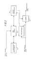
- Figure 2 shows an alternative implementation of deinterleaving apparatus according to the present invention.
- FIG. 1 is a block diagram of a portion of a HDTV receiver including a deinterleaving network 18 according to the principles of the present invention.
- a transmitted HDTV signal received by an antenna 10 is applied to an input processor 12.
- Input processor 12 typically includes a tuner and IF stage for down-converting the received signal to a lower frequency band. It also may include automatic gain control, filtering, timing/clock recovery networks and other circuitry as known.
- the output signal from unit 12 is equalized and demodulated by unit 14.
- the equalization process compensates for distortions in the data channel as known.
- the demodulator function recovers the baseband interleaved data from the modulated input signal.
- Such equalizer and demodulator functions are well known and are described, for example, in the reference text Digital Communication, Lee and Messerschmidt (Kluwer Academic Press, Boston, MA, USA, 1988 ).
- the interleaved data from equalizer/demodulator 14 is applied to a synchronizer circuit 27 within deinterleaving network 18, and to a signal input of memory 35.
- Synchronizer circuit 27 detects sync words in the interleaved data signal and provides output signals synchronized to the data indicating when the data starts.
- the sync words are not themselves interleaved, but occur at periodic intervals in time.
- the interleaved data may consist of repeated data blocks containing a sync word followed by 15 data words.
- the synchronization function is accomplished, for example, by sync detection circuitry incorporating byte recognition logic and a phase-locked loop.
- synchronizer circuit 27 is able to provide output signals to first and second address and memory controllers 20 and 25 for synchronizing address signals applied to memory 35 via a multiplexer 30, with the input interleaved data applied to the signal input of memory 35.
- Deinterleaving network 18 is configured such that controller 20 contains one deinterleaving function in the form of an algorithm, and controller 25 contains a different deinterleaving function also in the form of an algorithm.
- controller 20 may implement the Ramsey deinterleaving function and controller 25 the Forney deinterleaving function.
- These deinterleaving functions may be implemented as logic state machines, i.e. as a cyclic sequence of logic operations, each assigned a state with the sequence being potentially responsive to inputs.
- Outputs generated by the state machine operation are a function of any combination of state, previous or present input signal or previous or present output signal.
- the required logic equations to implement the state machine operation are programmed into a logic structure acting as a memory using well known methods.
- the Deinterleaver Select signal may be provided by various sources.
- this control signal is provided by a programmed microprocessor.
- a microprocessor has not been shown in Figure 1 in order to simplify the drawing.
- the control signal may also be provided by a manually operated switch source, for example, located in the HDTV receiver and external to deinterleaving network 18. In that case the switch source applies a selected binary logic level directly to a designated input of deinterleaving network 18.
- the control signal may be decoded from a received interleaved data stream.
- Controllers 20 and 25 produce a sequence of read and write addresses and associated memory control signals (such as read, write and output enable) which are passed via multiplexer 30 to memory 35.
- Memory 35 is essentially a shared memory which services whichever one of the two (or more) deinterleaving functions is selected.
- the addresses and associated memory control signals from controllers 20 and 25 are synchronized to the interleaved data input to memory 35 by the synchronization signals from synchronizer 27.
- the state of the Deinterleaver Select control signal input to multiplexer 30 determines which one of memory controller units 20 and 25 supplies memory address control signals to memory 35.
- Controllers 20, 25 produce respective memory write address control signals such that the input interleaved data is written into memory locations of memory 35 in the order in which the input interleaved data is received.
- Controllers 20 and 25 also produce respective memory read address signals to enable data to be read out of memory 35 in the desired deinterleaved order. This may be achieved, for example, by the state machine for the selected deinterleaver control unit producing the required sequence of addresses for reading the data out of memory 35.
- output data from memory 35 corresponding to the original (deinterleaved) data is produced as a function of a memory read process.
- the deinterleaving function may also be accomplished as a function of a memory write process, or as a function of both read and write processes.
- the disclosed deinterleaver network 18 realizes an advantage by using a plurality of address and memory controllers with an associated (shared) memory. That is, only a single shared memory is required, regardless of the number of deinterleaver functions that are implemented and available for selection
- the deinterleaved data output from memory 35 is descrambled by unit 38.
- Descrambling, as distinct from deinterleaving, has as its main goal the de-randomizing of data.
- the randomizing of the data is performed prior to transmission to disperse the transmitter signal energy. This helps to minimize co-channel interference and enhance timing recovery in the receiver. It also facilitates channel distortion compensation by an equalizer in the receiver.
- the descrambled output of unit 38 is decoded by decoder 40, which may be a Reed-Solomon decoder, for example. Corrected data packets from unit 40 are applied to a transport processor 44, which examines the header of each data packet to identify audio and video data.
- Transport processor 44 conveys the audio and video output data to appropriate decoders within unit 46.
- Decoded audio and video signals from unit 46 are respectively applied to an audio processor 52 and to a television video processor 50.
- Processors 50 and 52 format the audio and video signals in a manner appropriate for reproduction by unit 55.
- FIG. 2 Another embodiment of the invention is disclosed in Figure 2 .
- data needed to configure a memory controller to provide a desired deinterleaving function is contained within a memory 70.
- Memory 70 may contain more than one deinterleaving function.
- This data e.g. an algorithm, is loaded into a memory controller 80 by a data loader 75. This may be performed, for example, by data loader 75 reading data from memory 70 and writing this data to memory locations within controller 80.
- Data loader 75 selects which deinterleaving function to load in response to a Deinterleaver Select control signal. This control signal may be provided from a variety of sources as mentioned in connection with the embodiment of Figure 1 .
- Data loader 75 initiates the load operation upon power-up of the system, or upon a change in the logic level of the Deinterleaver Select control signal.
- Interleaved input data is applied to a synchronizer 73.
- Synchronizer 73 conveys sync signals to controller 80 for enabling controller 80 to synchronize memory address generation with the input interleaved data.
- the synchronization function is as described in connection with Figure 1 .
- Controller 80 produces write addresses so that the input interleaved data is written into the memory 85 in interleaved form.
- controller 80 produces read addresses to enable the stored data to be read out of memory 85 in the original deinterleaved order. That is, the read addressing of memory 85 is a function of deinterleaving data obtained from unit 70.
- the address generation function of controller 80 operates in the same way as described for controllers 20 and 25 in connection with Figure 1 .
- controllers 20, 25 and 80 may be implemented with microcontrollers or with discrete logic networks.
- the controllers 20 and 25 of Figure 1 may share circuitry.
- controllers 20, 25 and 80 of Figures 1 and 2 and may implement the deinterleaving address sequencing function in various ways.
- the deinterleaving function may be performed during the write cycle instead of during the read cycle described for the embodiment of Figure 1 .
- This write cycle deinterleaving is accomplished by writing the data to memory 35 or 85 locations in deinterleaved order, followed by reading the data from consecutive locations for output.
- the controllers may partially deinterleave the data during the write operation, while performing the remainder of the deinterleaving function during the read operation.
- the Deinterleaver Select control signal may be used to disable the unused controller in Figure 1 . This may be desirable to reduce noise or power dissipation.
- the control signal may also be used to disable the outputs of the controller not in use, for example, by disabling output signal tri-state buffers of the controller not in use. In this case the output signal tri-state buffers of the controller in use are enabled, and the buffers of the controllers not in use are disabled. Multiplexer 30 would not be needed in this case.
- More than one Deinterleaver Select control signal may be used. This may occur, for example, where two separate buffered versions of the same control signal are used by controllers 20 and 25. It may also occur when there are more than two address and memory controllers (each containing a different deinterleaving function) available for selection within deinterleaving network 18.
Landscapes
- Engineering & Computer Science (AREA)
- Multimedia (AREA)
- Signal Processing (AREA)
- Physics & Mathematics (AREA)
- Probability & Statistics with Applications (AREA)
- Theoretical Computer Science (AREA)
- Error Detection And Correction (AREA)
- Two-Way Televisions, Distribution Of Moving Picture Or The Like (AREA)
- Detection And Prevention Of Errors In Transmission (AREA)
- Television Systems (AREA)
- Transmission Systems Not Characterized By The Medium Used For Transmission (AREA)
Applications Claiming Priority (2)
| Application Number | Priority Date | Filing Date | Title |
|---|---|---|---|
| US08/346,950 US5563915A (en) | 1994-11-30 | 1994-11-30 | Data deinterleaver in a digital television signal decoding system |
| EP95118343A EP0715468A3 (fr) | 1994-11-30 | 1995-11-22 | Désinterlaceur de données dans un système décodeur de signaux de télévision numérique |
Related Parent Applications (2)
| Application Number | Title | Priority Date | Filing Date |
|---|---|---|---|
| EP95118343.3 Division | 1995-11-22 | ||
| EP95118343A Division EP0715468A3 (fr) | 1994-11-30 | 1995-11-22 | Désinterlaceur de données dans un système décodeur de signaux de télévision numérique |
Publications (2)
| Publication Number | Publication Date |
|---|---|
| EP2111040A2 true EP2111040A2 (fr) | 2009-10-21 |
| EP2111040A3 EP2111040A3 (fr) | 2010-06-02 |
Family
ID=23361708
Family Applications (3)
| Application Number | Title | Priority Date | Filing Date |
|---|---|---|---|
| EP95118343A Ceased EP0715468A3 (fr) | 1994-11-30 | 1995-11-22 | Désinterlaceur de données dans un système décodeur de signaux de télévision numérique |
| EP09159325A Withdrawn EP2111040A3 (fr) | 1994-11-30 | 1995-11-22 | Désentrelaceur de données dans un système de décodage de signaux de télévision numérique |
| EP06021202A Withdrawn EP1737239A3 (fr) | 1994-11-30 | 1995-11-22 | Désinterlaceur de données dans un système décodeur de signaux de télévision numérique |
Family Applications Before (1)
| Application Number | Title | Priority Date | Filing Date |
|---|---|---|---|
| EP95118343A Ceased EP0715468A3 (fr) | 1994-11-30 | 1995-11-22 | Désinterlaceur de données dans un système décodeur de signaux de télévision numérique |
Family Applications After (1)
| Application Number | Title | Priority Date | Filing Date |
|---|---|---|---|
| EP06021202A Withdrawn EP1737239A3 (fr) | 1994-11-30 | 1995-11-22 | Désinterlaceur de données dans un système décodeur de signaux de télévision numérique |
Country Status (11)
| Country | Link |
|---|---|
| US (1) | US5563915A (fr) |
| EP (3) | EP0715468A3 (fr) |
| JP (11) | JP4105245B2 (fr) |
| KR (1) | KR100387458B1 (fr) |
| CN (1) | CN1147135C (fr) |
| AU (1) | AU690760B2 (fr) |
| BR (1) | BR9505549A (fr) |
| CA (1) | CA2161468C (fr) |
| MY (1) | MY115379A (fr) |
| SG (1) | SG46157A1 (fr) |
| TW (1) | TW423778U (fr) |
Families Citing this family (12)
| Publication number | Priority date | Publication date | Assignee | Title |
|---|---|---|---|---|
| US5563915A (en) * | 1994-11-30 | 1996-10-08 | Thomson Consumer Electronics Inc. | Data deinterleaver in a digital television signal decoding system |
| KR100455115B1 (ko) * | 1997-03-05 | 2005-01-13 | 엘지전자 주식회사 | 그랜드얼라이언스고선명티브이(GrandAllianceHDTV)의복호회로 |
| CN1065392C (zh) * | 1998-08-04 | 2001-05-02 | 国家科学技术委员会高技术研究发展中心 | 采用动态ram实现数据交织和去交织的方法 |
| FI108822B (fi) * | 2000-02-14 | 2002-03-28 | Nokia Corp | Lomittelumenetelmä ja -järjestelmä |
| EP3340511B1 (fr) | 2004-10-12 | 2022-11-30 | TQ Delta, LLC | Partage de ressources dans un environnement de télécommunications |
| US20070076502A1 (en) | 2005-09-30 | 2007-04-05 | Pyeon Hong B | Daisy chain cascading devices |
| US20070140292A1 (en) * | 2005-12-17 | 2007-06-21 | Sestok Charles K Iv | De-interleaver synchronization methods and apparatus |
| AU2007257055A1 (en) | 2006-04-12 | 2007-12-13 | Aware, Inc. | Packet retransmission and memory sharing |
| JP5444669B2 (ja) | 2008-09-16 | 2014-03-19 | コニカミノルタ株式会社 | 画像形成装置 |
| US8359499B2 (en) | 2008-10-10 | 2013-01-22 | Csr Technology Inc. | Method and apparatus for deinterleaving in a digital communication system |
| WO2010042901A2 (fr) * | 2008-10-10 | 2010-04-15 | Auvitek International Ltd. | Procédé et appareil de désentrelacement dans un système de communication numérique |
| CN110177279B (zh) * | 2014-03-28 | 2021-10-08 | 联咏科技股份有限公司 | 视频处理装置与其视频处理电路 |
Citations (1)
| Publication number | Priority date | Publication date | Assignee | Title |
|---|---|---|---|---|
| US4063533A (en) | 1976-08-02 | 1977-12-20 | International Business Machines Corporation | Multiple brush developer applying apparatus with a toner diverter blade |
Family Cites Families (23)
| Publication number | Priority date | Publication date | Assignee | Title |
|---|---|---|---|---|
| JPS62190932A (ja) * | 1986-02-18 | 1987-08-21 | Nippon Telegr & Teleph Corp <Ntt> | インタリ−ブ方式 |
| JPS6432545A (en) * | 1987-07-28 | 1989-02-02 | Toshiba Corp | Data transmission system |
| JP2702950B2 (ja) * | 1987-12-16 | 1998-01-26 | 株式会社日立製作所 | Pcm信号記録再生装置 |
| US4901319A (en) * | 1988-03-18 | 1990-02-13 | General Electric Company | Transmission system with adaptive interleaving |
| US5134464A (en) * | 1990-11-16 | 1992-07-28 | North American Philips Corporation | Method and apparatus for the transmission and reception of a multicarrier digital television signal |
| US5063533A (en) * | 1989-04-10 | 1991-11-05 | Motorola, Inc. | Reconfigurable deinterleaver/interleaver for block oriented data |
| JP3047456B2 (ja) * | 1990-11-09 | 2000-05-29 | ソニー株式会社 | 衛星放送受信装置 |
| JPH04200083A (ja) * | 1990-11-29 | 1992-07-21 | Matsushita Electric Ind Co Ltd | 有料放送デコーダ |
| JPH04286779A (ja) * | 1991-03-17 | 1992-10-12 | Sony Corp | 磁気記録再生装置 |
| JP2772496B2 (ja) * | 1991-06-19 | 1998-07-02 | 三菱電機株式会社 | 映像信号記録装置 |
| JPH0589599A (ja) * | 1991-09-30 | 1993-04-09 | Toshiba Corp | 記録再生装置 |
| JPH05159475A (ja) * | 1991-12-11 | 1993-06-25 | Mitsubishi Electric Corp | ディジタル映像信号記録再生装置 |
| US5241563A (en) * | 1992-08-10 | 1993-08-31 | General Instrument Corporation | Method and apparatus for communicating interleaved data |
| KR0139192B1 (ko) * | 1992-09-15 | 1998-07-01 | 윤종용 | 디지탈전송데이타의 디인터리빙방법 및 장치 |
| JP2755067B2 (ja) * | 1992-09-25 | 1998-05-20 | 日本電気株式会社 | フレーム同期回路 |
| FR2697395B1 (fr) * | 1992-10-22 | 1994-12-30 | France Telecom | Procédé de codage-décodage hiérarchique d'un signal numérique, et système correspondant utilisés en télévision numérique. |
| US5359601A (en) * | 1992-10-30 | 1994-10-25 | Scientific-Atlanta, Inc. | Apparatus providing dynamic virtual service selection in a multi-service communications system |
| JP3581377B2 (ja) * | 1993-04-06 | 2004-10-27 | ソニー株式会社 | ディジタル多重伝送方法と装置 |
| US5486864A (en) * | 1993-05-13 | 1996-01-23 | Rca Thomson Licensing Corporation | Differential time code method and apparatus as for a compressed video signal |
| JP2999110B2 (ja) * | 1993-12-28 | 2000-01-17 | 株式会社ピーエフユー | 無線通信方法及び無線通信装置 |
| US5475716A (en) * | 1994-01-18 | 1995-12-12 | Gi Corporation | Method for communicating block coded digital data with associated synchronization/control data |
| JPH07254862A (ja) * | 1994-03-15 | 1995-10-03 | Sony Corp | インターリーブ回路およびディインターリーブ回路 |
| US5563915A (en) * | 1994-11-30 | 1996-10-08 | Thomson Consumer Electronics Inc. | Data deinterleaver in a digital television signal decoding system |
-
1994
- 1994-11-30 US US08/346,950 patent/US5563915A/en not_active Expired - Lifetime
-
1995
- 1995-10-16 MY MYPI95003100A patent/MY115379A/en unknown
- 1995-10-26 CA CA002161468A patent/CA2161468C/fr not_active Expired - Lifetime
- 1995-11-15 TW TW089215746U patent/TW423778U/zh not_active IP Right Cessation
- 1995-11-21 KR KR1019950042376A patent/KR100387458B1/ko not_active Expired - Lifetime
- 1995-11-22 EP EP95118343A patent/EP0715468A3/fr not_active Ceased
- 1995-11-22 EP EP09159325A patent/EP2111040A3/fr not_active Withdrawn
- 1995-11-22 EP EP06021202A patent/EP1737239A3/fr not_active Withdrawn
- 1995-11-28 BR BR9505549A patent/BR9505549A/pt not_active IP Right Cessation
- 1995-11-29 CN CNB951196391A patent/CN1147135C/zh not_active Expired - Lifetime
- 1995-11-29 AU AU39105/95A patent/AU690760B2/en not_active Expired
- 1995-11-30 JP JP31308695A patent/JP4105245B2/ja not_active Expired - Lifetime
- 1995-11-30 SG SG1995001979A patent/SG46157A1/en unknown
-
2007
- 2007-03-05 JP JP2007053964A patent/JP4424621B2/ja not_active Expired - Lifetime
-
2008
- 2008-04-10 JP JP2008102604A patent/JP4548676B2/ja not_active Expired - Lifetime
-
2010
- 2010-05-18 JP JP2010113901A patent/JP4605615B2/ja not_active Expired - Lifetime
- 2010-05-18 JP JP2010113895A patent/JP4986190B2/ja not_active Expired - Lifetime
-
2011
- 2011-12-22 JP JP2011280877A patent/JP2012075184A/ja active Pending
- 2011-12-22 JP JP2011280879A patent/JP2012060684A/ja active Pending
- 2011-12-22 JP JP2011280875A patent/JP2012105314A/ja active Pending
- 2011-12-22 JP JP2011280876A patent/JP2012075183A/ja active Pending
- 2011-12-22 JP JP2011280878A patent/JP2012060683A/ja active Pending
-
2014
- 2014-07-10 JP JP2014141931A patent/JP2014187718A/ja active Pending
Patent Citations (1)
| Publication number | Priority date | Publication date | Assignee | Title |
|---|---|---|---|---|
| US4063533A (en) | 1976-08-02 | 1977-12-20 | International Business Machines Corporation | Multiple brush developer applying apparatus with a toner diverter blade |
Non-Patent Citations (3)
| Title |
|---|
| FORNEY: "Burst-Correcting Codes for the Classic Bursty Channel", IEEE TRANSACTIONS ON COMMUNICATIONS TECHNOLOGY, vol. COM-19, October 1971 (1971-10-01) |
| LEE; MESSERSCHMIDT: "Digital Communication", 1988, KLUWER ACADEMIC PRESS |
| RAMSEY: "Realization of Optimum Interleavers", IEEE TRANSACTIONS ON INFORMATION THEORY, vol. IT-15, May 1970 (1970-05-01) |
Also Published As
| Publication number | Publication date |
|---|---|
| JP4548676B2 (ja) | 2010-09-22 |
| EP2111040A3 (fr) | 2010-06-02 |
| BR9505549A (pt) | 1997-11-04 |
| CN1126925A (zh) | 1996-07-17 |
| JP2012060684A (ja) | 2012-03-22 |
| CN1147135C (zh) | 2004-04-21 |
| JP4986190B2 (ja) | 2012-07-25 |
| JP2012075183A (ja) | 2012-04-12 |
| JP2007202180A (ja) | 2007-08-09 |
| JP4605615B2 (ja) | 2011-01-05 |
| US5563915A (en) | 1996-10-08 |
| JP2012105314A (ja) | 2012-05-31 |
| EP1737239A3 (fr) | 2007-08-01 |
| EP1737239A2 (fr) | 2006-12-27 |
| JP2014187718A (ja) | 2014-10-02 |
| AU690760B2 (en) | 1998-04-30 |
| CA2161468C (fr) | 1999-01-26 |
| JP4424621B2 (ja) | 2010-03-03 |
| CA2161468A1 (fr) | 1996-05-31 |
| JP2010178391A (ja) | 2010-08-12 |
| EP0715468A2 (fr) | 1996-06-05 |
| KR100387458B1 (ko) | 2003-10-17 |
| SG46157A1 (en) | 1998-02-20 |
| JP2012060683A (ja) | 2012-03-22 |
| JP2008236774A (ja) | 2008-10-02 |
| EP0715468A3 (fr) | 2000-01-12 |
| JP2010200372A (ja) | 2010-09-09 |
| JP2012075184A (ja) | 2012-04-12 |
| TW423778U (en) | 2001-02-21 |
| MY115379A (en) | 2003-05-31 |
| KR960020466A (ko) | 1996-06-17 |
| JPH08223505A (ja) | 1996-08-30 |
| JP4105245B2 (ja) | 2008-06-25 |
| AU3910595A (en) | 1996-06-06 |
Similar Documents
| Publication | Publication Date | Title |
|---|---|---|
| JP4548676B2 (ja) | データ・デインタリーバ | |
| US8130833B2 (en) | VSB transmission system for processing supplemental transmission data | |
| US7092447B2 (en) | Communication system in digital television | |
| KR101058038B1 (ko) | 디지털 텔레비젼 브로드캐스팅에서 로버스트 신호 전송 | |
| US8413012B2 (en) | Burst-error correction methods and apparatuses for wireless digital communications systems | |
| CN107070585B (zh) | 传达突发模式活动的装置和方法 | |
| US20020159520A1 (en) | Communication system in digital television | |
| WO2009051687A2 (fr) | Appareil et procédé de codage et de décodage de signaux | |
| JP2005130277A (ja) | 誤り訂正装置及び誤り訂正方法 | |
| HK1133335B (en) | Interleaver apparatus and receiver for a signal prodyced by the interleaver apparatus | |
| HK1133335A (en) | Interleaver apparatus and receiver for a signal prodyced by the interleaver apparatus |
Legal Events
| Date | Code | Title | Description |
|---|---|---|---|
| PUAI | Public reference made under article 153(3) epc to a published international application that has entered the european phase |
Free format text: ORIGINAL CODE: 0009012 |
|
| AC | Divisional application: reference to earlier application |
Ref document number: 0715468 Country of ref document: EP Kind code of ref document: P |
|
| AK | Designated contracting states |
Kind code of ref document: A2 Designated state(s): DE ES FR GB IT |
|
| PUAL | Search report despatched |
Free format text: ORIGINAL CODE: 0009013 |
|
| AK | Designated contracting states |
Kind code of ref document: A3 Designated state(s): DE ES FR GB IT |
|
| RIC1 | Information provided on ipc code assigned before grant |
Ipc: H04N 7/24 20060101AFI20100428BHEP |
|
| 17P | Request for examination filed |
Effective date: 20101123 |
|
| 17Q | First examination report despatched |
Effective date: 20110119 |
|
| APBK | Appeal reference recorded |
Free format text: ORIGINAL CODE: EPIDOSNREFNE |
|
| APBN | Date of receipt of notice of appeal recorded |
Free format text: ORIGINAL CODE: EPIDOSNNOA2E |
|
| APBR | Date of receipt of statement of grounds of appeal recorded |
Free format text: ORIGINAL CODE: EPIDOSNNOA3E |
|
| APAF | Appeal reference modified |
Free format text: ORIGINAL CODE: EPIDOSCREFNE |
|
| RAP1 | Party data changed (applicant data changed or rights of an application transferred) |
Owner name: THOMSON INC. |
|
| APBX | Invitation to file observations in appeal sent |
Free format text: ORIGINAL CODE: EPIDOSNOBA2E |
|
| APBT | Appeal procedure closed |
Free format text: ORIGINAL CODE: EPIDOSNNOA9E |
|
| STAA | Information on the status of an ep patent application or granted ep patent |
Free format text: STATUS: THE APPLICATION IS DEEMED TO BE WITHDRAWN |
|
| 18D | Application deemed to be withdrawn |
Effective date: 20170909 |