EP2111068B1 - Picozell-Basisstation für drahtlose Telekommunikationen zur Bereitstellung von Funkbereichskeulen und Verfahren zur Identifizierung welches Keulenunterset ein Benutzerendgerät abdeckt - Google Patents
Picozell-Basisstation für drahtlose Telekommunikationen zur Bereitstellung von Funkbereichskeulen und Verfahren zur Identifizierung welches Keulenunterset ein Benutzerendgerät abdeckt Download PDFInfo
- Publication number
- EP2111068B1 EP2111068B1 EP08007296.0A EP08007296A EP2111068B1 EP 2111068 B1 EP2111068 B1 EP 2111068B1 EP 08007296 A EP08007296 A EP 08007296A EP 2111068 B1 EP2111068 B1 EP 2111068B1
- Authority
- EP
- European Patent Office
- Prior art keywords
- base station
- user terminal
- lobes
- signal power
- pilot signal
- Prior art date
- Legal status (The legal status is an assumption and is not a legal conclusion. Google has not performed a legal analysis and makes no representation as to the accuracy of the status listed.)
- Not-in-force
Links
- 238000000034 method Methods 0.000 title claims description 29
- 230000001419 dependent effect Effects 0.000 claims description 15
- 238000005259 measurement Methods 0.000 description 13
- 210000004027 cell Anatomy 0.000 description 9
- 238000010586 diagram Methods 0.000 description 9
- 238000013459 approach Methods 0.000 description 8
- 238000012360 testing method Methods 0.000 description 8
- 238000004891 communication Methods 0.000 description 6
- 230000005540 biological transmission Effects 0.000 description 4
- 230000000694 effects Effects 0.000 description 4
- 230000003247 decreasing effect Effects 0.000 description 3
- 230000011664 signaling Effects 0.000 description 3
- 238000012986 modification Methods 0.000 description 2
- 230000004048 modification Effects 0.000 description 2
- 238000003491 array Methods 0.000 description 1
- 210000004271 bone marrow stromal cell Anatomy 0.000 description 1
- 230000001413 cellular effect Effects 0.000 description 1
- 238000012545 processing Methods 0.000 description 1
- 230000005855 radiation Effects 0.000 description 1
Images




Classifications
-
- H—ELECTRICITY
- H04—ELECTRIC COMMUNICATION TECHNIQUE
- H04W—WIRELESS COMMUNICATION NETWORKS
- H04W88/00—Devices specially adapted for wireless communication networks, e.g. terminals, base stations or access point devices
- H04W88/08—Access point devices
-
- H—ELECTRICITY
- H04—ELECTRIC COMMUNICATION TECHNIQUE
- H04W—WIRELESS COMMUNICATION NETWORKS
- H04W16/00—Network planning, e.g. coverage or traffic planning tools; Network deployment, e.g. resource partitioning or cells structures
- H04W16/24—Cell structures
- H04W16/28—Cell structures using beam steering
-
- H—ELECTRICITY
- H04—ELECTRIC COMMUNICATION TECHNIQUE
- H04W—WIRELESS COMMUNICATION NETWORKS
- H04W52/00—Power management, e.g. Transmission Power Control [TPC] or power classes
- H04W52/04—Transmission power control [TPC]
- H04W52/38—TPC being performed in particular situations
Definitions
- the present invention relates to telecommunications, in particular to wireless telecommunications.
- Wireless telecommunications systems are well-known. Many such systems are cellular, in that radio coverage is provided by a bundle of radio coverage areas known as cells. A base station that provides radio coverage is located in each cell. Traditional base stations provide coverage in relatively large geographic areas and the corresponding cells are often referred to as macrocells.
- picocells that are smaller than macrocells are sometimes referred to as microcells, picocells, or femtocells, but we use the term picocells generically for cells that are smaller than macrocells.
- One way to establish a picocell is to provide a picocell base station that operates within a relatively limited range within the coverage area of a macrocell.
- One example of use of a picocell base station is to provide wireless communication coverage within a building.
- the picocell base station is of a relatively low transmit power and hence each picocell is small compared to a macrocell.
- Picocell base stations can use broadband Internet Protocol connections as "backhaul”, in other words they are connected via picocell base station gateways to a Universal Mobile Telecommunications System (UMTS) core network, specifically each gateway is connected via the operator's Internet Protocol (IP) network to core network components such as to a UMTS Mobile Switching Centre (MSC) and a Signalling Gateway Support Node (SGSN).
- UMTS Universal Mobile Telecommunications System
- IP Internet Protocol
- MSC UMTS Mobile Switching Centre
- SGSN Signalling Gateway Support Node
- Picocell base stations are intended primarily for users belonging to a particular home or office. Picocell base stations may be private access or public access. In private access picocell base stations, access is restricted only to registered users, for example family members or particular groups of employees. In public access picocell base stations, other users may also use the picocell base station, subject to certain restrictions to protect the Quality of Service received by registered users.
- picocells there can be a large number of picocells within an area roughly equivalent to the size of a macrocell. Accordingly, there can be a large number of picocells in an operator's coverage area, such that conventional cell planning, as done to optimise location of base stations in macrocell networks, becomes impractical. This is particularly so as picocells are usually deployed by end-users or unskilled individuals installing picocell base stations where they choose in their offices and homes, for example in what is sometimes called a "plug-and-play" manner.
- picocells are deployed, there is an increase in the number of cells that a mobile user terminal detects and interacts with.
- a macrocell user moving along a road may often move in and out of range of picocell base stations, causing a sequence of handover attempt processes to and from the picocells.
- This disadvantageously produces an increase in the core network signalling and an increase in the risk that a call will be dropped due to the higher number of handover attempts. This can be to the detriment of data handling performance of the picocells.
- Handover attempts are one type of mobility procedure, and mobility procedures become more frequent in a network including picocells as compared to one with just macrocells.
- telecommunications standards can require that multiple network elements are involved, for example, such as MSCs and SGSNs in UMTS core networks to which picocell base stations are connected.
- MSCs and SGSNs in UMTS core networks to which picocell base stations are connected.
- a high number of such resource-intensive mobility procedures between multiple network elements is disadvantageous.
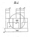
- This pattern is disadvantageous when the building 16 is an "awkward" shape, such as being long and thin.
- a typical English terraced house e.g. 13.5 metres long by 4.5 metres wide
- One known approach to improving this situation is to use multi-antenna arrays in picocell base stations, such that it becomes possible to adjust the gain (i.e. power) and hence the coverage area in selected directions. This improves the ability to provide good coverage within the building, without greater coverage outside the building that would cause an undesirable increase in mobility procedures.
- One known approach used in some Wireless Local Area Network access points having multiple antennas is to try randomly vanous predefined antenna gain configurations and select the one that provides the best coverage. This approach can improve the link quality for a current transmission As it can be considered a "trial and error” approach, it cannot be relied on to quickly provide good coverage within an awkwardly shaped building.
- each antenna of the array has a separate receive chain.
- a separate RF receiver, detector and decoder is provided for each sector.
- the present invention is characterised over the disclosure of WO2004/114460 in that the base station for a penod applying an adjusted pilot signal power in respect of the - selected subset of the lobes, the user terminal detecting received pilot signal power and retorting to the base station information dependent upon the detected signal power, the base station determining dependent upon said information whether or not the user terminal is located in the selected subset of lobes, in which further steps are undertaken of:
- An example of the present invention is a method, in a base station for wireless telecommunications having multiple directional antenna elements each providing a corresponding radio coverage lobe, of identifying which subset of the lobes covers a user terminal.
- the base station is a picocell base station.
- the method comprises the following steps A user terminal is positioned within the coverage area of the base station. A subset of the lobes is selected. The base station applies for a period an adjusted signal power in respect of the selected subset of the lobes. The signal power is detected and information dependent upon the detected signal power is provided. The base station uses said information to determine whether or not the user terminal is located in the selected subset of lobes
- the present invention provides a picocell base station for wireless telecommunications, the picocell base station comprising multiple directional antenna elements each providing a corresponding radio coverage lobe, a detector, a controller, and a receiver, the detector being operative to identify which subset of the lobes covers a user terminal, in which:
- the selector is further operative to select a sub-group of the subset of the lobes
- the pilot signal generator is further operative to adjust pilot signal power for a period in the selected sub-group
- the receiver is operative to receive further information of the measured pilot signal power reported by a user terminal, and the detector uses said further information to determine whether or not the user terminal is located in the selected subgroup of lobes.
- the picocell base station is operative such that the further steps are repeated with further sub-group(s) of the sub-group of the subset of lobes being considered until the base station determines the lobe in which the user terminal is located
- the picocell base station is operative to determine the lobe in which the user terminal is located, and further comprising a coverage optimiser operative to alter the size of said lobe in which the user terminal is located so as to keep the rate of unwanted handover attempts from user terminals in said lobe within predetermined limits.
- a base station 22 for wireless telecommunications
- the base station has a radio coverage area 24 that is often referred to as a macrocell
- the geographic extent of the macrocell 24 depends on the capabilities of the base station 22 and the surrounding geography.
- a picocell base station unit (PCBSU) 30 provides wireless communications within a picocell 32.
- a picocell is a radio coverage area In this example, the radio coverage area of the picocell 30 is much less than that of the macrocell 24
- the picocell 32 corresponds in size to a user's home
- PCBSU picocell base station-unit
- a mobile terminal 44 within the macrocell 24 it is possible for a mobile terminal 44 within the macrocell 24 to communicate with the macrocell base station 22 in known manner.
- the mobile terminal 44 enters into a picocell 32 for which the mobile terminal is registered for, in other words has access nights for, communications within the picocell base station 30, it is desirable to handover the connection with the mobile terminal from the macrocell to the picocell.
- the user of mobile terminal 44 is a preferred user to use the picocell 32.
- the picocell base.station unit 30 transmits pilot signals 29 in the picocell 32.
- PCBSU Picocell Base Station Unit
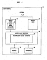
- the picocell base station consists of an array 46 of eight antenna-elements 48 each connected to a gain controller 50.
- the gain controller 50 enables the gain that is applied to signals to/from each antenna to be adjusted
- the PCBSU 30 includes a transmit chain 52 that provides signals for transmission to the gain controller 50
- the transmit chain 52 includes a pilot signal generator 54 and an encoder (not shown).
- the PCBSU also includes a receive chain 56 including a radio frequency signal receiver (not shown), a detector (not shown) and a decoder (not shown).
- the receive chain 56 processes signals received by antennas 48 then passed via the gain controller 50 to the receive chain 56.
- Both the transmit chain 52 and receive chain 56 are connected to a higher layer processor 58.
- the higher layer processor 58 includes an auto-configuration controller 60 that includes both a radio lobe detector 62 and a coverage optimiser 64.
- the higher layer processor 58 is connected by an Internet Protocol broadband connection ("backhaul") 66, such as an Ethernet or DSL link, to the rest of the telecommunications world.
- backhaul Internet Protocol broadband connection
- PCBSU picocell base station unit
- the user terminal 44 includes a higher layer processor 66 connected to a microphone 68 and speaker 70.
- a transmit chain 72 and receiver chain 74 each connect the higher layer processor 66 to an antenna 76.
- the receive chain 74 includes a pilot signal detector 78.
- the higher layer processor 66 includes a measurement report generator 80.
- the pilot signal detector 78 acts to detect the strength of pilot signals received by the user terminal 44 and the measurement report generator 80 acts to include that information in a measurement report that is passed via the transmit chain 72 to the antenna 76 for transmission to the picocell base station unit.
- each antenna 48 of the array 46 of the picocell base station unit 30 provides a corresponding "lobe" (also known as a beam) of radio coverage, a determination is made of which lobe serves a connected user terminal 44 best.
- the size of that lobe is varied (by adjustment of pilot signal gain) dependent upon the number of unwanted handover attempts occurring. This is explained in more detail below.
- the determination of the best lobe to a user terminal in the building is made by a series of gain modifications to the lobes and uses the measurement reporting capability of the user terminal.
- the user terminal frequently provides feedback to the picocell base station unit 30 of received pilot signal strength. This feedback is in measurement reports.
- Measurement reporting by a user terminal is known to the skilled reader in the art, for example being defined in Standards such as Universal Mobile Telecommunications System (UMTS).
- UMTS Universal Mobile Telecommunications System
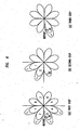
- transmitted pilot signal gain is temporarily increased by a predetermined amount in each of a set of four adjacent lobes 1, 2, 3, 4.
- the user terminal (denoted UE in Figure 6 ) sends a measurement report indicating that an increase in received pilot signal gain was detected.
- the lobe detector 62 in the picocell base station unit 30 determines that the user terminal is covered by one of these four lobes 1,2,3,4.
- the picocell base station unit 30 refines the search by temporarily increasing the gain of two of the four lobes 1,2,3,4. In this example, the gain of lobes 1 annd 2 are increased. In this example, the user terminal is not covered by those two lobes, so the user terminal reports that no increase in received pilot signal gain was detected. Accordingly the lobe detector 62 in the picocell base station unit 30 determines that the user terminal is covered by one of the other two lobes 3,4.
- the picocell base station unit 30 refines the search yet further by temporarily increasing the pilot signal gain of one of the remaining two "candidate" lobes 3,4. In this example, this was done for lobe 3, in other words the "correct" lobe was chosen such that the user terminal sends a measurement report indicating that an increase in received pilot signal gain was detected. According, the lobe detector 62 of the PCBSU 30 has detected the lobe that serves the user terminal in its current location best.
- a coverage improvement process is performed based on the number of mobility events as explained below.
- Figure 7 shows, referring back to Figure 4 , how the coverage optimiser 64 of the auto-configuration controller 60 of the PCBSU 30 acts to control the pilot signal gain of the lobe in question generated by the pilot signal generator.
- step 210) when transmitting (step 205) pilot signals using a default pilot signal gain, handover events are monitored (step 210) to detect and determine the rate of unwanted handover events (step 212).
- the rate of unwanted handover events in other words, unwanted mobility events, is the number of such events per unit time from mobiles not registered to use the PCBSU or from passing macrocell users who briefly, i.e. within a certain time period, handover to the PCBSU 30 then handback immediately to the macrocell network as they pass by.
- Registered mobile user terminals can include both "home" user terminals and permitted “visitor" user terminals.
- the aim is to maximise indoor coverage for the identified lobe without increasing the number of such unwanted handover events to an unacceptable level.
- the second threshold is less stringent than the first threshold. If Yes, then the pilot signal gain is decreased (step 230) by a predetermined decrement Delta2. Accordingly the lobe shrinks in size. If No, the pilot signal gain is not reduced.
- step 210,212 The counting of unwanted events (steps 210,212) is then restarted.
- Both the measurement times t1,t2 and the gain increment Delta1 and gain decrement Delta2, are adapted over time. This is to improve the speed to reach a stable state having appropriate lobe sizes such that there is good coverage inside the building but little coverage outside. This is also to prevent frequent flipping between increasing and decreasing pilot signal gain. For example, at first t2 is low so that rapid lobe size increase is possible until a first unwanted mobility event is detected, in which case t2 is then increased significantly so as to slow down the rate of increase.
- Figure 8 shows an example of the resulting coverage, in which various user terminals in various lobes have been identified and so the sizes of the lobes adjusted. It will be seen that the eight lobes 1,2,3,4,5,6,7,8 (defined by pilot signal gains) have taken various sizes that practically maximise coverage within the building 16' without increasing the number of unwanted handover events to an unacceptable level. Significant radio coverage by the PCBSU in the street 20' and into neighbouring buildings 18' is avoided.
- predictive testing of lobes and/or enhanced testing can be undertaken as described below.
- One option to increase the speed to reach a stable lobe pattern is to use statistics on in which lobe, or lobes, frequent unwanted handovers have happened in the past, in order to select which lobe or lobes to temporarily increase the gain of first, in a test cycle.
- this lobe can be tested first, on its own before step (a) shown in Figure 6 and described above.
- step (a) shown in Figure 6 and described above.
- the user terminal entering the building will be located within that lobe which has a temporary increase in pilot signal gain so will provide a measurement report indicating a consequential increase in received pilot signal gain.
- steps (a), (b) and (c) as described above in relation to Figure 6 .
- signal reflections by walls can contribute to a received signal. This can mean that, in determination of the best lobe, temporarily increasing the pilot signal gain of a lobe in which the user terminal is not located could nevertheless result in the user terminal detecting and so reporting a consequential received pilot signal gain. This can result in unreliable identification of the best lobe for a user terminal in a particular location.
- a first step four adjacent lobes are tested first. Specifically, transmitted pilot signal gain is temporarily increased by a predetermined amount in each of a set of four adjacent lobes 1, 2, 3, 4.
- the user terminal (denoted UE in Figure 9 ) sends a measurement report indicating that an increase in received pilot signal gain was detected.
- the other four lobes are tested. Specifically, transmitted pilot signal gain is temporarily increased by a predetermined amount in each of a set of four adjacent lobes 5,6,7,8, and the user terminal sens a further measurement report.
- the group of lobes that provides the highest increase in pilot power detected by the user is selected as that within which the user terminal is located, say lobes 1 to 4 in this example.
- the picocell base station unit refines the search by further testing the group of lobes (lobes 1,2,3,4 in this example) determined as giving the higher increase of in pilot signal detected. Specifically as a third step (denoted c in Figure 9 ), the gain of a sub-group consisting of two lobes, namely lobes 1,2, is temporarily increased; and then as a fourth step (denoted d in Figure 9 ) the gain of the other subgroup consisting of two lobes, namely lobes 3,4, are temporanly increased. Again the subgroup that provides the highest increase in pilot signal gain received by the user terminal is selected as the correct one (in this case, lobes 3 and 4).
- the picocell base station unit refines the search yet further by testing the lobes in the selected sub-set. Specifically, as a fifth step (denoted e in Figure 9 ), by the pilot signal gain is temporarily increased of one of the lobes (lobe 3 in this example) then the other (lobe 4 in this example). The lobe in respect of which the higher increase in pilot signal received by the user terminal is detected is taken to be the lobe in which the user terminal is located, in other words, the lobe that serves the user terminal in its current location best
- This vanant is similar to that described in relation to Figure 4 , basically except that it receives signals from selected lobes that are gain-adjusted rather than signals for transmission in the selected lobes
- the picocell base station consists of an array 46' of eight antenna-elements 48' each connected to a gain controller 50'
- the gain controller 50' enables the gain that is applied to receive signals from each antenna to be adjusted
- the PCBSU 30 includes a receive chain 56' including a radio frequency signal receiver (not shown), a receive signal detector 57 and a decoder (not shown).
- the receive chain 56' processes signals received by antennas 48' then passed via the gain controller 50' to the receive chain 56'.
- Both the transmit chain 52' and receive chain 56' are connected to a higher layer processor 58'.
- the higher layer processor 58' includes an auto-configuration controller 60' that includes both a radio lobe detector 62' and coverage optimiser 64'.
- the higher layer processor 58' is connected by an Internet Protocol broadband
- backhaul such as an Ethernet or DSL link
- the operation of the picocell base station unit (PCBSU) 30' is that the user terminal sends an uplink signal to the base station 30' and receive signals in selected subsets of the lobes are gain-adjusted by the gain controller 50'.
- the receive signals are processed by the receive chain 56' including detecting the receive signal from selected lobes, in order to, as described previously, determine which subset of the lobes covers the user terminal. Subgroups of selected subsets of lobes are selected and "tested" in an iterative manner as described previously, for example to identify the particular lobe in which the user terminal is located.
Landscapes
- Engineering & Computer Science (AREA)
- Computer Networks & Wireless Communication (AREA)
- Signal Processing (AREA)
- Mobile Radio Communication Systems (AREA)
Claims (12)
- Verfahren, in einer Basisstation (30) für drahtlose Telekommunikationen mit mehrfachen Richtantennenelementen (48), welche jeweils eine entsprechende Funkbereichskeule bereitstellen, zur Identifizierung, welcher Teilsatz der Keulen ein Benutzerendgerät (44) abdeckt,
wobei die Basisstation (30) eine Picozellen-Basisstation ist und das Verfahren die folgenden Schritte umfasst:Positionieren eines Benutzerendgeräts (44) innerhalb des Abdeckungsbereichs der Basisstation (30),Auswählen eines Teilsatzes der Keulen,dadurch gekennzeichnet, dassdie Basisstation (30) für eine Zeitspanne eine angepasste Pilotsignalleistung in Bezug auf den ausgewählten Teilsatz der Keulen anwendet,das Benutzerendgerät (44) die empfangene Pilotsignalleistung erfasst und in Abhängigkeit von der erfassten Signalleistung Informationen an die Basisstation (30) meldet,die Basisstation (30) in Abhängigkeit von den besagten Informationen ermittelt (62), ob sich das Benutzerendgerät (44) in dem ausgewählten Teilsatz von Keulen befindet oder nicht, wobei weiterhin die folgenden Schritte durchgeführt werden:Auswählen einer Untergruppe des Teilsatzes der Keulen,Anwenden, durch die Basisstation (30), für eine Zeitspanne, einer angepassten Pilotsignalleistung in Bezug auf die ausgewählte Untergruppe,Erfassen, durch das Benutzerendgerät (44), der empfangenen Pilotsignalleistung und Melden von Informationen in Abhängigkeit von der erfassten Signalleistung an die Basisstation (30),Ermitteln (62) durch die Basisstation (30), in Abhängigkeit von den besagten Informationen, ob sich das Benutzerendgerät (44) in der ausgewählten Untergruppe befindet oder nicht. - Verfahren nach Anspruch 1, wobei das Benutzerendgerät (44) eine erhöhte empfangene Pilotleistung erfasst und meldet (80), und wobei die Basisstation (30) ermittelt (62), dass sich das Benutzerendgerät (44) innerhalb des ausgewählten Teilsatzes von Keulen, in welchen die Pilotleistung erhöht wurde, befindet.
- Verfahren nach Anspruch 1, wobei die besagte angepasste Signalleistung durch eine an der Basisstation (30) auf empfangene Signale von dem ausgewählten Teilsatz von Keulen angewendete Verstärkungsanpassung (50) bereitgestellt wird.
- Verfahren nach Anspruch 1, wobei der ausgewählte Teilsatz von Keulen der Hälfte der Keulen entspricht.
- Verfahren nach Anspruch 1, wobei die weiteren Schritte mit (einer) weiteren Untergruppe(n) der berücksichtigten Untergruppe des Teilsatzes von Keulen so lange wiederholt werden, bis die Basisstation (30) die Keule (62), in welcher sich das Benutzerendgerät (44) befindet, ermittelt.
- Verfahren nach einem beliebigen der vorstehenden Ansprüche, dazu führend, dass die Keule, in welcher sich das Benutzerendgerät (44) befindet, ermittelt wird, und
Verändern der Größe der besagten Keule, in welcher sich das Benutzerendgerät (44) befindet, so dass die Rate von unerwünschten Handover-Versuchen von Benutzerendgeräten in der besagten Keule in vorbestimmten Grenzen gehalten wird,
wobei die unerwünschten Handover-Versuche von Benutzerendgeräten durch nicht an der Basisstation (30) registrierte Benutzerendgeräte erfolgen. - Verfahren nach Anspruch 6, wobei, wenn die Rate einen ersten Grenzwert unterschreitet, die Pilotsignalleistung in Bezug auf diejenige Keule, die als die Keule, in welcher sich das Benutzerendgerät (44) befindet, ermittelt wurde, erhöht wird, um die Größe der besagten Keule zu erhöhen.
- Verfahren nach Anspruch 6, wobei, wenn die Rate einen zweiten Grenzwert überschreitet, die Pilotsignalleistung in Bezug auf diejenige Keule, die als die Keule, in welcher sich das Benutzerendgerät (44) befindet, ermittelt wurde, reduziert wird, um die Größe der besagten Keule zu reduzieren.
- Verfahren nach Anspruch 1, wobei die Basisstation (30) für eine Zeitspanne die Pilotsignalleistung in Bezug auf den ausgewählten Teilsatz der Keulen erhöht und anschließend für eine Zeitspanne die Pilotsignalleistung in Bezug auf die anderen Teilsätze der Keulen erhöht,
wobei das Verfahren das Erfassen, durch das Benutzerendgerät (44), der empfangenen Pilotsignalleistung und das Melden (80) von Informationen darüber, welcher der Teilsätze die größere Erhöhung in der erfassten Pilotsignalleistung bereitstellt, und
das Ermitteln (62), durch die Basisstation (30), in welchem Teilsatz der Keulen sich das Benutzerendgerät (44) befindet, in Abhängigkeit von den besagten Informationen umfasst. - Picozellen-Basisstation (30) für drahtlose Telekommunikationen,
wobei die Picozellen-Basisstation mehrfache Richtantennenelementen (48), welche jeweils eine entsprechende Funkbereichskeule bereitstellen, einen Detektor (62), einen Controller (50) und einen Empfänger (56) umfasst,
wobei der Detektor (62) betriebsfähig ist, um zu identifizieren, welcher Teilsatz der Keulen ein Benutzerendgerät abdeckt, wobei
der Detektor (62) eine Auswahleinrichtung umfasst, welche betriebsfähig ist, um einen Teilsatz der Keulen auszuwählen;
dadurch gekennzeichnet, dass
der Controller (50) betriebsfähig ist, um die Pilotsignalleistung für eine Zeitspanne in Bezug auf den ausgewählten Teilsatz der Keulen anzupassen,
der Empfänger (56) betriebsfähig ist, um Informationen über die empfangene und von einem Benutzerendgerät gemessene Pilotsignalleisung zu empfangen; und
der Detektor (62) die Informationen in Abhängigkeit davon, ob sich das Benutzerendgerät (44) in dem ausgewählten Teilsatz von Keulen befindet oder nicht, ermittelt,
wobei die Auswahleinrichtung weiterhin betriebsfähig ist, um eine Untergruppe des Teilsatzes der Keulen auszuwählen,
wobei der Controller (50) weiterhin betriebsfähig ist, um die Leistung von weiteren Pilotsignalen in Bezug auf die ausgewählte Untergruppe für eine weitere Zeitspanne anzupassen,
wobei der Empfänger (56) weiterhin betriebsfähig ist, um zweite Informationen in Abhängigkeit von der in der besagten weiteren Zeitspanne empfangenen und von dem Benutzerendgerät (44) gemessenen Pilotsignalleistung zu empfangen; und
der Detektor (62) weiterhin betriebsfähig ist, um in Abhängigkeit von den besagten zweiten Informationen zu ermitteln, ob sich das Benutzerendgerät (44) in der ausgewählten Untergruppe befindet oder nicht. - Picozellen-Basisstation (30) nach Anspruch 10, weiterhin umfassend einen Pilotsignalgenerator (54), wobei die Signalleistung eine Pilotsignalleistung ist und der Empfänger betriebsfähig ist, um Informationen über die von einem Benutzerendgerät (44) gemessene und gemeldete (80) Pilotsignalleistung zu empfangen.
- Picozellen-Basisstation (30) gemäß Anspruch 10, wobei der Controller (50) betriebsfähig ist, um die Signalleistung durch Anpassen der empfangenen Signalverstärkung für eine Zeitspanne anzupassen, wobei die von einem Benutzerendgerät (44) empfangene Signalleistung an der Basisstation gemessen wird, um die Informationen bereitzustellen.
Priority Applications (6)
| Application Number | Priority Date | Filing Date | Title |
|---|---|---|---|
| EP08007296.0A EP2111068B1 (de) | 2008-04-14 | 2008-04-14 | Picozell-Basisstation für drahtlose Telekommunikationen zur Bereitstellung von Funkbereichskeulen und Verfahren zur Identifizierung welches Keulenunterset ein Benutzerendgerät abdeckt |
| JP2011504337A JP5036905B2 (ja) | 2008-04-14 | 2009-03-13 | 無線カバレッジローブを提供する無線遠隔通信のためのピコセル基地局、及びローブのいずれのサブセットがユーザ端末を範囲に含むかを識別する方法 |
| KR1020107022575A KR101173534B1 (ko) | 2008-04-14 | 2009-03-13 | 무선 커버리지 로브들을 제공하는 무선 전기통신들을 위한 피코셀 기지국 및 로브들의 어떤 서브세트가 사용자 단말을 커버하는지를 식별하는 방법 |
| PCT/EP2009/001917 WO2009127306A1 (en) | 2008-04-14 | 2009-03-13 | A picocell base station for wireless telecommunications providing radio coverage lobes, and a method of identifying which subset of the lobes covers a user terminal |
| US12/419,391 US8265701B2 (en) | 2008-04-14 | 2009-04-07 | Picocell base station for wireless telecommunications providing radio coverage lobes, and a method of identifying which subset of the lobes covers a user terminal |
| CN200910134354.4A CN101562818B (zh) | 2008-04-14 | 2009-04-14 | 用于无线电信的提供无线覆盖波瓣的微微蜂窝基站和识别哪个波瓣子集覆盖用户终端的方法 |
Applications Claiming Priority (1)
| Application Number | Priority Date | Filing Date | Title |
|---|---|---|---|
| EP08007296.0A EP2111068B1 (de) | 2008-04-14 | 2008-04-14 | Picozell-Basisstation für drahtlose Telekommunikationen zur Bereitstellung von Funkbereichskeulen und Verfahren zur Identifizierung welches Keulenunterset ein Benutzerendgerät abdeckt |
Publications (2)
| Publication Number | Publication Date |
|---|---|
| EP2111068A1 EP2111068A1 (de) | 2009-10-21 |
| EP2111068B1 true EP2111068B1 (de) | 2014-01-01 |
Family
ID=39722691
Family Applications (1)
| Application Number | Title | Priority Date | Filing Date |
|---|---|---|---|
| EP08007296.0A Not-in-force EP2111068B1 (de) | 2008-04-14 | 2008-04-14 | Picozell-Basisstation für drahtlose Telekommunikationen zur Bereitstellung von Funkbereichskeulen und Verfahren zur Identifizierung welches Keulenunterset ein Benutzerendgerät abdeckt |
Country Status (6)
| Country | Link |
|---|---|
| US (1) | US8265701B2 (de) |
| EP (1) | EP2111068B1 (de) |
| JP (1) | JP5036905B2 (de) |
| KR (1) | KR101173534B1 (de) |
| CN (1) | CN101562818B (de) |
| WO (1) | WO2009127306A1 (de) |
Families Citing this family (4)
| Publication number | Priority date | Publication date | Assignee | Title |
|---|---|---|---|---|
| JP5365546B2 (ja) * | 2010-02-25 | 2013-12-11 | 日本電気株式会社 | 屋内無線通信システム、フェムトセル基地局、無線電力制御方法、無線電力制御プログラムおよび記録媒体 |
| KR101150831B1 (ko) * | 2010-08-04 | 2012-06-13 | 성균관대학교산학협력단 | 펨토셀 기지국 및 그의 통신 방법 |
| JP5968791B2 (ja) * | 2011-02-10 | 2016-08-10 | ノキア ソリューションズ アンド ネットワークス オサケユキチュア | サーバ装置、基地局装置、小型基地局装置及び干渉制御方法 |
| CN105992220B (zh) * | 2015-03-04 | 2020-04-17 | 上海诺基亚贝尔股份有限公司 | 用于室内无线网络的小区内频率重用的方法和基带单元 |
Family Cites Families (10)
| Publication number | Priority date | Publication date | Assignee | Title |
|---|---|---|---|---|
| JPH09200115A (ja) * | 1996-01-23 | 1997-07-31 | Toshiba Corp | 無線通信システムにおける無線基地局のアンテナ指向性制御方法および可変指向性アンテナ |
| US6900775B2 (en) * | 1997-03-03 | 2005-05-31 | Celletra Ltd. | Active antenna array configuration and control for cellular communication systems |
| US6694154B1 (en) * | 1997-11-17 | 2004-02-17 | Ericsson Inc. | Method and apparatus for performing beam searching in a radio communication system |
| JP3335900B2 (ja) * | 1998-02-27 | 2002-10-21 | 松下電器産業株式会社 | 干渉除去装置及び干渉除去方法 |
| JP3701844B2 (ja) * | 2000-06-08 | 2005-10-05 | 株式会社エヌ・ティ・ティ・ドコモ | 移動通信システムの管理方法 |
| JP2002171553A (ja) * | 2000-11-29 | 2002-06-14 | Sony Corp | 無線端末装置探索システム、無線端末装置及び無線端末装置探索方法 |
| CN1809976A (zh) * | 2003-06-19 | 2006-07-26 | 美商智慧财产权授权股份有限公司 | 以空间多样化为基础存取点的天线操控 |
| US7047046B2 (en) | 2003-06-19 | 2006-05-16 | Ipr Licensing, Inc. | Antenna steering for an access point based upon probe signals |
| GB0525161D0 (en) * | 2005-12-09 | 2006-01-18 | Airspan Networks Inc | Antenna system for wireless communications |
| US7761058B2 (en) * | 2006-03-24 | 2010-07-20 | Samsung Electronics Co., Ltd. | Method and procedure for self discovery of small office or home interior structure by means of acoustic sensing and profiling |
-
2008
- 2008-04-14 EP EP08007296.0A patent/EP2111068B1/de not_active Not-in-force
-
2009
- 2009-03-13 KR KR1020107022575A patent/KR101173534B1/ko not_active Expired - Fee Related
- 2009-03-13 JP JP2011504337A patent/JP5036905B2/ja not_active Expired - Fee Related
- 2009-03-13 WO PCT/EP2009/001917 patent/WO2009127306A1/en not_active Ceased
- 2009-04-07 US US12/419,391 patent/US8265701B2/en not_active Expired - Fee Related
- 2009-04-14 CN CN200910134354.4A patent/CN101562818B/zh not_active Expired - Fee Related
Also Published As
| Publication number | Publication date |
|---|---|
| US20090258680A1 (en) | 2009-10-15 |
| KR101173534B1 (ko) | 2012-08-13 |
| JP2011521514A (ja) | 2011-07-21 |
| JP5036905B2 (ja) | 2012-09-26 |
| KR20100136492A (ko) | 2010-12-28 |
| CN101562818A (zh) | 2009-10-21 |
| US8265701B2 (en) | 2012-09-11 |
| EP2111068A1 (de) | 2009-10-21 |
| WO2009127306A1 (en) | 2009-10-22 |
| CN101562818B (zh) | 2014-07-09 |
Similar Documents
| Publication | Publication Date | Title |
|---|---|---|
| EP2220878B1 (de) | Schnittstellenverwaltung in einem drahtlosen kommunikationssystem mittels wiederverwendung von subframezeit | |
| CN102119560B (zh) | 用于对在节点b处自调整发射功率和灵敏度电平进行补偿的自动参数调整的方法和装置 | |
| EP2243306B1 (de) | Interferenzkontrolle in einem drahtlosen kommunikationssystem anhand von frequenzselektiver übertragung | |
| US9301265B2 (en) | Access point transmit power control | |
| US9497714B2 (en) | Power control for a network of access points | |
| EP2506625A1 (de) | Kleinzellige Basisstation mit mehrfachen Antennen und Verfahren zur Steuerung der Empfangsmuster durch Auswahl eines Untersatzes der zu verwendenden Antennen | |
| EP2220774A2 (de) | Interferenzkontrolle in einem drahtlosen kommunikationssystem anhand strahl- und nulllenkung | |
| KR20110051096A (ko) | 이종망에서 간섭 조절 방법 및 클러스터, 클러스터의 신규 등록방법 | |
| Morita et al. | Adaptive power level setting of femtocell base stations for mitigating interference with macrocells | |
| EP2111068B1 (de) | Picozell-Basisstation für drahtlose Telekommunikationen zur Bereitstellung von Funkbereichskeulen und Verfahren zur Identifizierung welches Keulenunterset ein Benutzerendgerät abdeckt | |
| Claussen et al. | Macrocell offloading benefits in joint macro-and femtocell deployments | |
| Gong et al. | Cochannel interference in cellular fixed broadband access systems with directional antennas | |
| Razavi et al. | Self-configuring switched multi-element antenna system for interference mitigation in femtocell networks | |
| Razavi et al. | Controlling local service access in wireless cellular networks |
Legal Events
| Date | Code | Title | Description |
|---|---|---|---|
| PUAI | Public reference made under article 153(3) epc to a published international application that has entered the european phase |
Free format text: ORIGINAL CODE: 0009012 |
|
| AK | Designated contracting states |
Kind code of ref document: A1 Designated state(s): AT BE BG CH CY CZ DE DK EE ES FI FR GB GR HR HU IE IS IT LI LT LU LV MC MT NL NO PL PT RO SE SI SK TR |
|
| AX | Request for extension of the european patent |
Extension state: AL BA MK RS |
|
| 17P | Request for examination filed |
Effective date: 20091020 |
|
| AKX | Designation fees paid |
Designated state(s): AT BE BG CH CY CZ DE DK EE ES FI FR GB GR HR HU IE IS IT LI LT LU LV MC MT NL NO PL PT RO SE SI SK TR |
|
| RAP1 | Party data changed (applicant data changed or rights of an application transferred) |
Owner name: ALCATEL-LUCENT USA INC. |
|
| GRAP | Despatch of communication of intention to grant a patent |
Free format text: ORIGINAL CODE: EPIDOSNIGR1 |
|
| RIC1 | Information provided on ipc code assigned before grant |
Ipc: H04W 88/08 20090101AFI20130527BHEP Ipc: H04W 16/28 20090101ALN20130527BHEP Ipc: H04W 52/38 20090101ALN20130527BHEP |
|
| INTG | Intention to grant announced |
Effective date: 20130619 |
|
| REG | Reference to a national code |
Ref country code: DE Ref legal event code: R079 Ref document number: 602008029590 Country of ref document: DE Free format text: PREVIOUS MAIN CLASS: H04W0016000000 Ipc: H04W0088080000 |
|
| GRAP | Despatch of communication of intention to grant a patent |
Free format text: ORIGINAL CODE: EPIDOSNIGR1 |
|
| 111Z | Information provided on other rights and legal means of execution |
Free format text: AT BE BG CH CY CZ DE DK EE ES FI FR GB GR HR HU IE IS IT LI LT LU LV MC MT NL NO PL PT RO SE SI SK TR Effective date: 20130410 |
|
| RIC1 | Information provided on ipc code assigned before grant |
Ipc: H04W 16/28 20090101ALN20130828BHEP Ipc: H04W 88/08 20090101AFI20130828BHEP Ipc: H04W 52/38 20090101ALN20130828BHEP |
|
| INTG | Intention to grant announced |
Effective date: 20130909 |
|
| RAP1 | Party data changed (applicant data changed or rights of an application transferred) |
Owner name: ALCATEL LUCENT |
|
| RIC1 | Information provided on ipc code assigned before grant |
Ipc: H04W 88/08 20090101AFI20130830BHEP Ipc: H04W 52/38 20090101ALN20130830BHEP Ipc: H04W 16/28 20090101ALN20130830BHEP |
|
| RIN1 | Information on inventor provided before grant (corrected) |
Inventor name: HO, LESTER TSE WEE Inventor name: CLAUSSEN, HOLGER |
|
| GRAS | Grant fee paid |
Free format text: ORIGINAL CODE: EPIDOSNIGR3 |
|
| GRAA | (expected) grant |
Free format text: ORIGINAL CODE: 0009210 |
|
| AK | Designated contracting states |
Kind code of ref document: B1 Designated state(s): AT BE BG CH CY CZ DE DK EE ES FI FR GB GR HR HU IE IS IT LI LT LU LV MC MT NL NO PL PT RO SE SI SK TR |
|
| REG | Reference to a national code |
Ref country code: GB Ref legal event code: FG4D |
|
| REG | Reference to a national code |
Ref country code: CH Ref legal event code: EP |
|
| REG | Reference to a national code |
Ref country code: IE Ref legal event code: FG4D |
|
| REG | Reference to a national code |
Ref country code: AT Ref legal event code: REF Ref document number: 648060 Country of ref document: AT Kind code of ref document: T Effective date: 20140215 |
|
| REG | Reference to a national code |
Ref country code: DE Ref legal event code: R096 Ref document number: 602008029590 Country of ref document: DE Effective date: 20140220 |
|
| REG | Reference to a national code |
Ref country code: NL Ref legal event code: VDEP Effective date: 20140101 |
|
| REG | Reference to a national code |
Ref country code: AT Ref legal event code: MK05 Ref document number: 648060 Country of ref document: AT Kind code of ref document: T Effective date: 20140101 |
|
| REG | Reference to a national code |
Ref country code: LT Ref legal event code: MG4D Ref country code: GB Ref legal event code: 732E Free format text: REGISTERED BETWEEN 20140529 AND 20140604 |
|
| PG25 | Lapsed in a contracting state [announced via postgrant information from national office to epo] |
Ref country code: IS Free format text: LAPSE BECAUSE OF FAILURE TO SUBMIT A TRANSLATION OF THE DESCRIPTION OR TO PAY THE FEE WITHIN THE PRESCRIBED TIME-LIMIT Effective date: 20140501 Ref country code: LT Free format text: LAPSE BECAUSE OF FAILURE TO SUBMIT A TRANSLATION OF THE DESCRIPTION OR TO PAY THE FEE WITHIN THE PRESCRIBED TIME-LIMIT Effective date: 20140101 |
|
| REG | Reference to a national code |
Ref country code: CH Ref legal event code: PCOW Free format text: NEW ADDRESS: 148/152 ROUTE DE LA REINE, 92100 BOULOGNE-BILLANCOURT (FR) |
|
| REG | Reference to a national code |
Ref country code: FR Ref legal event code: GC Effective date: 20140602 |
|
| RAP2 | Party data changed (patent owner data changed or rights of a patent transferred) |
Owner name: ALCATEL LUCENT |
|
| PG25 | Lapsed in a contracting state [announced via postgrant information from national office to epo] |
Ref country code: PT Free format text: LAPSE BECAUSE OF FAILURE TO SUBMIT A TRANSLATION OF THE DESCRIPTION OR TO PAY THE FEE WITHIN THE PRESCRIBED TIME-LIMIT Effective date: 20140502 Ref country code: ES Free format text: LAPSE BECAUSE OF FAILURE TO SUBMIT A TRANSLATION OF THE DESCRIPTION OR TO PAY THE FEE WITHIN THE PRESCRIBED TIME-LIMIT Effective date: 20140101 Ref country code: AT Free format text: LAPSE BECAUSE OF FAILURE TO SUBMIT A TRANSLATION OF THE DESCRIPTION OR TO PAY THE FEE WITHIN THE PRESCRIBED TIME-LIMIT Effective date: 20140101 Ref country code: SE Free format text: LAPSE BECAUSE OF FAILURE TO SUBMIT A TRANSLATION OF THE DESCRIPTION OR TO PAY THE FEE WITHIN THE PRESCRIBED TIME-LIMIT Effective date: 20140101 Ref country code: NL Free format text: LAPSE BECAUSE OF FAILURE TO SUBMIT A TRANSLATION OF THE DESCRIPTION OR TO PAY THE FEE WITHIN THE PRESCRIBED TIME-LIMIT Effective date: 20140101 Ref country code: CY Free format text: LAPSE BECAUSE OF FAILURE TO SUBMIT A TRANSLATION OF THE DESCRIPTION OR TO PAY THE FEE WITHIN THE PRESCRIBED TIME-LIMIT Effective date: 20140101 Ref country code: FI Free format text: LAPSE BECAUSE OF FAILURE TO SUBMIT A TRANSLATION OF THE DESCRIPTION OR TO PAY THE FEE WITHIN THE PRESCRIBED TIME-LIMIT Effective date: 20140101 |
|
| PG25 | Lapsed in a contracting state [announced via postgrant information from national office to epo] |
Ref country code: LV Free format text: LAPSE BECAUSE OF FAILURE TO SUBMIT A TRANSLATION OF THE DESCRIPTION OR TO PAY THE FEE WITHIN THE PRESCRIBED TIME-LIMIT Effective date: 20140101 Ref country code: HR Free format text: LAPSE BECAUSE OF FAILURE TO SUBMIT A TRANSLATION OF THE DESCRIPTION OR TO PAY THE FEE WITHIN THE PRESCRIBED TIME-LIMIT Effective date: 20140101 Ref country code: BE Free format text: LAPSE BECAUSE OF FAILURE TO SUBMIT A TRANSLATION OF THE DESCRIPTION OR TO PAY THE FEE WITHIN THE PRESCRIBED TIME-LIMIT Effective date: 20140101 |
|
| REG | Reference to a national code |
Ref country code: DE Ref legal event code: R097 Ref document number: 602008029590 Country of ref document: DE |
|
| PG25 | Lapsed in a contracting state [announced via postgrant information from national office to epo] |
Ref country code: DK Free format text: LAPSE BECAUSE OF FAILURE TO SUBMIT A TRANSLATION OF THE DESCRIPTION OR TO PAY THE FEE WITHIN THE PRESCRIBED TIME-LIMIT Effective date: 20140101 Ref country code: CZ Free format text: LAPSE BECAUSE OF FAILURE TO SUBMIT A TRANSLATION OF THE DESCRIPTION OR TO PAY THE FEE WITHIN THE PRESCRIBED TIME-LIMIT Effective date: 20140101 Ref country code: RO Free format text: LAPSE BECAUSE OF FAILURE TO SUBMIT A TRANSLATION OF THE DESCRIPTION OR TO PAY THE FEE WITHIN THE PRESCRIBED TIME-LIMIT Effective date: 20140101 Ref country code: EE Free format text: LAPSE BECAUSE OF FAILURE TO SUBMIT A TRANSLATION OF THE DESCRIPTION OR TO PAY THE FEE WITHIN THE PRESCRIBED TIME-LIMIT Effective date: 20140101 |
|
| PLBE | No opposition filed within time limit |
Free format text: ORIGINAL CODE: 0009261 |
|
| STAA | Information on the status of an ep patent application or granted ep patent |
Free format text: STATUS: NO OPPOSITION FILED WITHIN TIME LIMIT |
|
| PG25 | Lapsed in a contracting state [announced via postgrant information from national office to epo] |
Ref country code: SK Free format text: LAPSE BECAUSE OF FAILURE TO SUBMIT A TRANSLATION OF THE DESCRIPTION OR TO PAY THE FEE WITHIN THE PRESCRIBED TIME-LIMIT Effective date: 20140101 Ref country code: PL Free format text: LAPSE BECAUSE OF FAILURE TO SUBMIT A TRANSLATION OF THE DESCRIPTION OR TO PAY THE FEE WITHIN THE PRESCRIBED TIME-LIMIT Effective date: 20140101 Ref country code: MC Free format text: LAPSE BECAUSE OF FAILURE TO SUBMIT A TRANSLATION OF THE DESCRIPTION OR TO PAY THE FEE WITHIN THE PRESCRIBED TIME-LIMIT Effective date: 20140101 Ref country code: LU Free format text: LAPSE BECAUSE OF FAILURE TO SUBMIT A TRANSLATION OF THE DESCRIPTION OR TO PAY THE FEE WITHIN THE PRESCRIBED TIME-LIMIT Effective date: 20140414 |
|
| REG | Reference to a national code |
Ref country code: CH Ref legal event code: PL |
|
| 26N | No opposition filed |
Effective date: 20141002 |
|
| REG | Reference to a national code |
Ref country code: DE Ref legal event code: R097 Ref document number: 602008029590 Country of ref document: DE Effective date: 20141002 |
|
| REG | Reference to a national code |
Ref country code: IE Ref legal event code: MM4A |
|
| PG25 | Lapsed in a contracting state [announced via postgrant information from national office to epo] |
Ref country code: CH Free format text: LAPSE BECAUSE OF NON-PAYMENT OF DUE FEES Effective date: 20140430 Ref country code: LI Free format text: LAPSE BECAUSE OF NON-PAYMENT OF DUE FEES Effective date: 20140430 |
|
| REG | Reference to a national code |
Ref country code: FR Ref legal event code: PLFP Year of fee payment: 8 |
|
| PG25 | Lapsed in a contracting state [announced via postgrant information from national office to epo] |
Ref country code: IE Free format text: LAPSE BECAUSE OF NON-PAYMENT OF DUE FEES Effective date: 20140414 |
|
| PG25 | Lapsed in a contracting state [announced via postgrant information from national office to epo] |
Ref country code: SI Free format text: LAPSE BECAUSE OF FAILURE TO SUBMIT A TRANSLATION OF THE DESCRIPTION OR TO PAY THE FEE WITHIN THE PRESCRIBED TIME-LIMIT Effective date: 20140101 |
|
| PG25 | Lapsed in a contracting state [announced via postgrant information from national office to epo] |
Ref country code: MT Free format text: LAPSE BECAUSE OF FAILURE TO SUBMIT A TRANSLATION OF THE DESCRIPTION OR TO PAY THE FEE WITHIN THE PRESCRIBED TIME-LIMIT Effective date: 20140101 |
|
| REG | Reference to a national code |
Ref country code: FR Ref legal event code: PLFP Year of fee payment: 9 |
|
| PG25 | Lapsed in a contracting state [announced via postgrant information from national office to epo] |
Ref country code: NO Free format text: LAPSE BECAUSE OF FAILURE TO SUBMIT A TRANSLATION OF THE DESCRIPTION OR TO PAY THE FEE WITHIN THE PRESCRIBED TIME-LIMIT Effective date: 20140401 |
|
| PG25 | Lapsed in a contracting state [announced via postgrant information from national office to epo] |
Ref country code: BG Free format text: LAPSE BECAUSE OF FAILURE TO SUBMIT A TRANSLATION OF THE DESCRIPTION OR TO PAY THE FEE WITHIN THE PRESCRIBED TIME-LIMIT Effective date: 20140101 |
|
| PG25 | Lapsed in a contracting state [announced via postgrant information from national office to epo] |
Ref country code: GR Free format text: LAPSE BECAUSE OF FAILURE TO SUBMIT A TRANSLATION OF THE DESCRIPTION OR TO PAY THE FEE WITHIN THE PRESCRIBED TIME-LIMIT Effective date: 20140402 Ref country code: IT Free format text: LAPSE BECAUSE OF FAILURE TO SUBMIT A TRANSLATION OF THE DESCRIPTION OR TO PAY THE FEE WITHIN THE PRESCRIBED TIME-LIMIT Effective date: 20140101 |
|
| PG25 | Lapsed in a contracting state [announced via postgrant information from national office to epo] |
Ref country code: TR Free format text: LAPSE BECAUSE OF FAILURE TO SUBMIT A TRANSLATION OF THE DESCRIPTION OR TO PAY THE FEE WITHIN THE PRESCRIBED TIME-LIMIT Effective date: 20140101 Ref country code: HU Free format text: LAPSE BECAUSE OF FAILURE TO SUBMIT A TRANSLATION OF THE DESCRIPTION OR TO PAY THE FEE WITHIN THE PRESCRIBED TIME-LIMIT; INVALID AB INITIO Effective date: 20080414 |
|
| REG | Reference to a national code |
Ref country code: FR Ref legal event code: PLFP Year of fee payment: 10 |
|
| REG | Reference to a national code |
Ref country code: FR Ref legal event code: PLFP Year of fee payment: 11 |
|
| PGFP | Annual fee paid to national office [announced via postgrant information from national office to epo] |
Ref country code: FR Payment date: 20220308 Year of fee payment: 15 |
|
| PGFP | Annual fee paid to national office [announced via postgrant information from national office to epo] |
Ref country code: GB Payment date: 20230302 Year of fee payment: 16 |
|
| PGFP | Annual fee paid to national office [announced via postgrant information from national office to epo] |
Ref country code: DE Payment date: 20230307 Year of fee payment: 16 |
|
| PG25 | Lapsed in a contracting state [announced via postgrant information from national office to epo] |
Ref country code: FR Free format text: LAPSE BECAUSE OF NON-PAYMENT OF DUE FEES Effective date: 20230430 |
|
| REG | Reference to a national code |
Ref country code: DE Ref legal event code: R119 Ref document number: 602008029590 Country of ref document: DE |
|
| GBPC | Gb: european patent ceased through non-payment of renewal fee |
Effective date: 20240414 |
|
| PG25 | Lapsed in a contracting state [announced via postgrant information from national office to epo] |
Ref country code: DE Free format text: LAPSE BECAUSE OF NON-PAYMENT OF DUE FEES Effective date: 20241105 |
|
| PG25 | Lapsed in a contracting state [announced via postgrant information from national office to epo] |
Ref country code: GB Free format text: LAPSE BECAUSE OF NON-PAYMENT OF DUE FEES Effective date: 20240414 |
|
| PG25 | Lapsed in a contracting state [announced via postgrant information from national office to epo] |
Ref country code: GB Free format text: LAPSE BECAUSE OF NON-PAYMENT OF DUE FEES Effective date: 20240414 Ref country code: DE Free format text: LAPSE BECAUSE OF NON-PAYMENT OF DUE FEES Effective date: 20241105 |