EP2111072A2 - Appareil de communication et procédé pour la commande de l'appareil de communication - Google Patents
Appareil de communication et procédé pour la commande de l'appareil de communication Download PDFInfo
- Publication number
- EP2111072A2 EP2111072A2 EP09155514A EP09155514A EP2111072A2 EP 2111072 A2 EP2111072 A2 EP 2111072A2 EP 09155514 A EP09155514 A EP 09155514A EP 09155514 A EP09155514 A EP 09155514A EP 2111072 A2 EP2111072 A2 EP 2111072A2
- Authority
- EP
- European Patent Office
- Prior art keywords
- packet
- mobile station
- address
- base station
- return
- Prior art date
- Legal status (The legal status is an assumption and is not a legal conclusion. Google has not performed a legal analysis and makes no representation as to the accuracy of the status listed.)
- Withdrawn
Links
Images






























Classifications
-
- H—ELECTRICITY
- H04—ELECTRIC COMMUNICATION TECHNIQUE
- H04W—WIRELESS COMMUNICATION NETWORKS
- H04W8/00—Network data management
- H04W8/02—Processing of mobility data, e.g. registration information at HLR [Home Location Register] or VLR [Visitor Location Register]; Transfer of mobility data, e.g. between HLR, VLR or external networks
- H04W8/08—Mobility data transfer
- H04W8/082—Mobility data transfer for traffic bypassing of mobility servers, e.g. location registers, home PLMNs or home agents
-
- H—ELECTRICITY
- H04—ELECTRIC COMMUNICATION TECHNIQUE
- H04W—WIRELESS COMMUNICATION NETWORKS
- H04W80/00—Wireless network protocols or protocol adaptations to wireless operation
- H04W80/04—Network layer protocols, e.g. mobile IP [Internet Protocol]
Definitions
- the embodiments discussed herein are related to a communication apparatus and a control method of the communication apparatus.
- HA Home Agent
- a packet in communication between a mobile station 11 and a mobile station 12, a packet is transferred via an home agent 41 (home agent is hereinafter referred to as HA).
- home agent home agent is hereinafter referred to as HA
- packets transmitted from the mobile stations 11 and 12 are transferred to the HA 41 via a base station 21, an access service network-gateway (hereinafter, simply referred to as ASN-GW) 31, and a router 51.
- ASN-GW access service network-gateway
- a dynamic host configuration protocol server (DHCP) 61 sets an IP address of the mobile station 11 via the base station 21.
- the base station 21 is actually connected to a communication network.
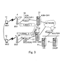
- Fig. 3 illustrates an example in which the mobile station 11 moves the management from the base station 21 to a base station 22, i.e., handover is executed.
- a tunnel between the base station 21 and the ASN-GW 31 is used before the moving.
- an access service network router (ASN router) 56 intervenes at an interval between the base stations 21 and 22 and the ASN-GW 31.
- ASN router access service network router
- paths using a tunnel between the ASN-GW 31 and an ASN-GW 32 and a tunnel between the ASN-GW 32 and the base station 22 are added.
- an ASN router 56 intervenes between the base station 21 and the ASN-GW 31. Further, an ASN router 57 intervenes between the base station 22 and the ASN-GW 32. As a consequence, in a state in which the IP address of the mobile station 11 is kept, a communication path having a start point of the ASN-GW 31 is established for the mobile station 11.
- Fig. 4 illustrates a flow of a packet in the communication with packet transfer between the mobile station 11 and the mobile station 12 by using a technology of Worldwide Interoperability for Microwave Access (hereinafter, referred as to WiMAX) (refer to Document 1).
- WiMAX Worldwide Interoperability for Microwave Access
- a communication network is connected to the Internet via an ISP-GW (Internet Service Provider-Gateway) 52.
- ISP-GW Internet Service Provider-Gateway
- AAA/SIP Authentication Authorization Accounting/Session Initiation Protocol
- Fig. 5 illustrates a flow of the packet in the communication with the transfer of the packet between the mobile station 11 and the mobile station 12 by using 3rd Generation Partnership Project (3GPP) technology (refer to Documents 1 to 4).
- 3GPP 3rd Generation Partnership Project
- the packet transmitted from the mobile station 11 is transferred to an Long Term Evolution (LTE) anchor (hereinafter, referred to as an LTE anchor) 41A via an evolved node B (hereinafter, referred to as a base station, Access Gateway (hereinafter, referred to as aGW) 31A, and an ISP router 51.
- LTE Long Term Evolution
- eNB evolved node B
- GW Access Gateway
- HSS/SIP server 53A Home Subscriber Server/Session Initiation Protocol (hereinafter, referred to as HSS/SIP server) server 53A is provided.
- HSS/SIP server 53A Home Subscriber Server/Session Initiation Protocol
- the basic structure and processing of devices forming a communication system with the 3GPP technology as will be described later with reference to Fig. 5 and Figs. 7, 8 , and 42 to 61 can properly use a well-known 3GPP technology, and a specific description thereof is omitted.
- Fig. 6 illustrates an example of implementing a protocol stack from a Mobile Station (hereinafter, referred to as MS) to the ASN-GW via a Base Station (hereinafter, referred to as BS) with the WiMAX technology.
- Fig. 7 illustrates an example of implementing a protocol stack of U-Plane (uplink) from the mobile station (MS) to the aGW via the eNB with the 3GPP technology.
- Fig. 8 illustrates an example of implementing a protocol stack of U-Plane (uplink) from the mobile station (MS) to the aGW via the base station (eNB) with the 3GPP technology upon terminating a Packet Data Conergence Protocol (hereinafter, referred to as PDCP) at the eNB, similarly to Fig. 7 .
- PDCP Packet Data Conergence Protocol
- a communication apparatus includes a first transfer unit for transferring a first packet received from a base station to a second home agent, the first packet to be sent from a first mobile station to a second mobile station as a destination being transferred to the second home agent, the first terminal and the second terminal being managed by a first home agent and the second home agent respectively, the first mobile station and the second mobile station being located in a region under control of the base station, a second transfer unit for transferring the first packet sent back from the second home agent to the base station, the first packet encapsulated in the second home agent so as to include an address of the communication apparatus as an destination address, and a return instruction unit for issuing to the base station an instruction for directly transferring a second packet to the second mobile station when a predetermined condition is satisfied, the instruction being including information of a network address translation for resetting an address of the second home agent to an address of the first home agent, the second packet to be sent from the first mobile station to the second mobile station as a destination being transferred to the second
- the ASN-GW 31 instructs the return of the packet to a base station 21 that manages mobile stations 11 and 12 for mutual the communication.
- the "return of packet" uses a path for returning the packet transmitted from the mobile station 11 is returned by the base station 21 and directly transmitting the packet to the mobile station 12. Therefore, the instruction of the return of the packet is an instruction for allowing the received packet to performing the processing to the base station 21.
- the communication path of the "return of the packet" is different from a path via the router 51 and the HA 41 illustrated in Fig. 1 . Therefore, the processing load of the packet of the ASN-GW 31, router 51, and HA 41 is reduced, and communication paths among the base station 21, ASN-GW 31, router 51, and HA 41 are not used. Therefore, the load of transmission resources is efficiently reduced.
- the ASN-GW monitors a communication state of the mobile station thereunder, and instructs the return of the packet as necessary.
- the base station receives the instruction of the return of the packet from the ASN-GW, and sets a path, which is illustrated with the dashed line in Fig. 9 , for returning and transmitting the received packet from the first mobile station to the second mobile station.
- the ASN-GW resets the setting of the path so as to solve the state.
- an ASN-GW apparatus that manages the base station checks the address of the received packet from the mobile station such as a Personal Digital Assistant (PDA).
- PDA Personal Digital Assistant
- NAT Network Address Translation
- the structure of a tunnel between the base stations and an instruction for changing a routine table are performed to the base station.
- the packet is returned in the base station and between the base stations. As a consequence, the processing load and the load of transmission resources of the ASN-GW are reduced.
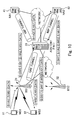
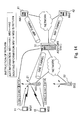
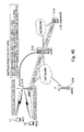
- Fig. 10 is a diagram for explaining an operation upon moving to a state for returning the packet in the base station according to the first embodiment.
- Fig. 10 illustrates a flow of the packet in the communication when the two mobile stations 11 and 12 under the management of the base station 21 communicate data with each other.
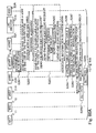
- Fig. 11 illustrates an operation sequence of a flow of the packet in the mutual communication between the two mobile stations 11 and 12 under the management of the base station 21 illustrated in Fig. 10 .
- step S1 in step S1 (hereinafter, a term of "step” will be omitted), the mobile station 11 executes a file transfer protocol (hereinafter, referred to as FTP), and transfers the packet to the base station 21.
- FTP file transfer protocol
- the base station 21 receives the file transfer protocol, it is determined whether or not the packet is registered as a target of the return of the packet (S2). It is not determined that the packet is not the target of the return of the packet, the packet is encapsulated, the address thereof is set as the ASN-GW 31, and the packet is transferred to the ASN-GW 31 (S3).
- the ASN-GW 31 receives the packet and performs return adaptation determination, which will be later (S4).
- the address of the internal header subjected to the encapsulation is replaced from the address of the mobile station 11 to that of the HA 41 (S5), and the address of the HA 41 is transferred to the HA 42.
- the HA 42 receives the address thereof, performs the encapsulation of the MIP tunnel (S6), and transfers the packet to the ASN-GW 31.
- the ASN-GW 31 receives the packet, similarly performs the return adaptation determination (S7), encapsulates a Generic Routing Encapsulation (GRE) tunnel (S8), and transfers the packet to the base station 21.
- S7 return adaptation determination
- GRE Generic Routing Encapsulation
- the base station 21 receives the packet, and resets the encapsulation of the GRE tunnel (S9), and transfers the packet to the mobile station 12.
- the ASN-GW 31 determines whether or not the destination of the packet or the address thereof on the transmission source is an address concerning a mobile IP, such as the HA 41 or HA 42, upon transmitting the packet to the HA 42 and receiving the packet from the HA 42.
- the ASN-GW 31 determines whether or not the packet is registered as the target of the return of the packet, in the base station under the management of the ASN-GW 31.
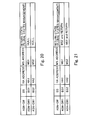
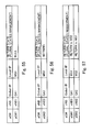
- the ASN-GW 31 manages therein a return management table illustrated in Fig. 12 .
- the ASN-GW 31 analyzes the traffic situation of the packet used by itself or the protocol (FTP, streaming, etc.) of the packet, thereby determining the return adaptation.
- the determination of the return adaptation it is determined whether or not the packet under a condition (destination and transmission source) is registered as the target of the return of the packet.
- NAT information and routing information necessary for returning the packet are created on the basis of the return management table. Referring to Fig. 13 , a return state of the return management table is updated. Further, referring to Fig. 14 , the return of the packet is instructed to the base station 21, thereby setting the return of the packet to the base station 21.
- the base station 21 With the setting of the return of the packet, the base station 21 performs the NAT processing and routine processing to the packet from the mobile station 11 on the basis of the NAT information and routing information. As a consequence, the packet is returned from the base station 21, and is transferred to the mobile station 12.
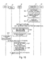
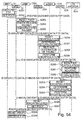
- Fig. 15 illustrates an operation sequence upon setting the return of the packet illustrated in Fig. 14 .
- the ASN-GW 31 determines the return adaptation. Then, it is determined that the packet matching a predetermined condition (destination and transmission source) is to be registered as the target of the return of the packet (S21), the return management table is updated. That is, as illustrated in Fig. 13 , "return to MS 2" and “return to MS 1" are written to a return state column of the corresponding record with respect o the packet of the communication between the mobile station 11 and the mobile station 12 (S22). Further, the ASN-GW 31 creates necessary NAT information and routing information so that the base station 21 embodies the return of the corresponding packet, and transmits the created information to the base station 21 (S23).
- the base station 21 that receives the information sets the NAT information and routing information thereto (S24), and registers the corresponding packet of (the packet of the communication between the mobile station 11 and the mobile station 12) as the target of the return of the packet (S25).
- the mobile station 11 performs FTP processing, and transfers the packet addressed to the mobile station 12 to the base station 21 (S26). Then, the base station 21 checks to see if the packet is registered as the target of the return of the packet (S27). Since the packet matches the condition (destination and transmission source) registered in S25, the NAT processing and routine processing are performed to return the packet (S28). As a consequence, the base station 21 replaces the address of the destination of the packet to the address of the mobile station 12, and also replaces the address on the transmission source to the address of the HA 41 in the mobile station 11. As a consequence, the packet is returned and the resultant packet is directly transferred to the mobile station 12.
- the ASN-GW 31 analyzes the traffic situation of the packet used by itself and the protocol of the packet, thereby determining the return adaptation.
- this will be specifically described.
- the amount of passage packet of the specific mobile station is monitored. Upon detecting the passage of a prescribed amount of packet or more at the specific mobile station, it is determined that the corresponding packet is to be registered as the target of the return of the packet.
- the ASN-GW 31 continuously performs reception processing of a communication task (thread/process) allocated in advance to the mobile stations every mobile station (S41 to S45 in Fig. 16 ). Further, a task for checking the return as another task sequentially selects a specific one of the mobile stations as a monitoring target thereof, and determines the mobile station for selection on the basis of the amount of passage packet (S51 to S55 in Fig. 16 ).
- the ASN-GW 31 receives the packet (S41), the communication task every mobile station determines whether or not the packet is from the mobile station as the monitoring target determined in S51, which will be described later (S42). When the packet is from the mobile station as the monitoring target (Yes), it is determined whether or not the destination of the packet is the address under management of the ASN-GW 31 (S43). When the destination of the packet is the address under management of the ASN-GW 31 (Yes), the size of the packet is obtained (S44). The IP address as the destination and the size of packet are counted up, in accordance with the mobile station on the transmission side (S45).
- the task for checking the return determines the mobile station as the monitoring target (S51), and waits for a prescribed time (S52).
- the IP address and the size of packet of the corresponding mobile station (obtained in S45) are obtained (S53). It is determined on the basis of the counting, whether or not the IP address for recording the amount of packet not-less-than a prescribed one exists (S54). When the IP address for recording the amount of packet not-less-than a prescribed one exists (Yes), it is determined that the packet of the communication between the corresponding mobile station and the mobile station at the IP address is to be registered as the target of the return of the packet (S55).
- the protocol of the passage packet of the specific mobile station is monitored. When a large amount of packet in FTP or streaming is received and transmitted at the protocol, it is determined that the packet of the communication between the corresponding mobile stations is to be registered as the target of the return of the packet.
- the ASN-GW 31 receives the packet (S61), and it is determined whether or not the destination is the address under management of the ASN-GW 31 (S62). When the destination is the address under management of the ASN-GW 31 (Yes), the protocol is obtained. When a large amount of packet in FTP or streaming is received and transmitted at the protocol (Yes in S63), it is determined that the packet of the communication between the mobile stations is to be registered as the target of the return of the packet (S64).
- the packet is transferred from the mobile station 11 to the mobile station 12.
- the mobile stations 11 and 12 are individually managed by the base stations 21 and 22, unlike the first embodiment.
- the structure other than that is similar to that according to the first embodiment, and overlapped portions are not described.
- the ASN-GW 31 and the base stations 21 and 22 may have the structures according to the first and second embodiments and, alternatively, may have the structure according to the first embodiment or the second embodiment.
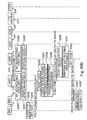
- Fig. 19 is a sequence diagram for explaining the operation of the communication system illustrated in Fig. 18 .
- the mobile station 11 executes the FTP, and transfers the packet to the base station 21.
- the base station 21 receives the packet and then determines whether or not the packet is registered as the target of the return of the packet (S72). When it is not determined that the packet is registered as the target of the return of the packet, the packet is encapsulated and the encapsulated packet is transferred to the ASN-GW 31 as the destination (S73).
- the ASN-GW 31 receives the packet, and embodies the return adaptation determination (S74).
- the ASN-GW 31 replaces the address of the internal header subjected to the encapsulation from that of the mobile station 11 to that of the HA 41 as the FA (S75), and transfers the replaced address to the HA 42.
- the HA 42 receives the transferred address, and encapsulates the MIP tunnel (S76), and transfers the packet to the ASN-GW 31.
- the ASN-GW 31 receives the packet and similarly determines the return adaptation (S77), encapsulates the GRE tunnel (S78), and transfers the packet to the base station 22.
- the base station 22 receives the packet and resets the encapsulation of the GRE tunnel (S79), and transfers the packet to the mobile station 12.
- the ASN-GW 31 determines whether or not the destination of the packet or the address thereof on the transmission source is the address concerning the mobile IP, such as the HA 41 or the HA 42.
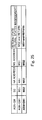
- the ASN-GW31 determines whether or not the packet under the condition (destination and transmission source) is registered as the target of the return of the packet by the base station under the management of the ASN-GW 31. In order to perform the determination, the ASN-GW 31 manages therein the return management table illustrated in Fig. 20 .
- the ASN-GW 31 analyzes the traffic situation of the packet used by itself or the protocol of the packet (FTP or streaming), thereby determining the return adaptation.
- the determination of return adaptation it is determined whether or not the packet of the communication matching the condition (destination and transmission source) is to be registered as the target of the return of the packet.
- the NAT information and routing information necessary for returning the packet is created on the basis of the return management table. Referring to Fig. 21 , the return state of the return management table is updated. Further, referring to Fig. 22 , the return of the packet is instructed to the base stations 21 and 22, thereby setting the return of the packet to the base stations 21 and 22.
- the base station 21 With setting of the return of the packet, the base station 21 performs the NAT processing and routine processing of the packet from the mobile station 11 on the basis of the NAT information and routing information. As a consequence, the packet is directly transferred from the base station 21 to the base station 22 and is thereafter transferred to the mobile station 12. That is, in the case illustrated according to the second embodiment, the packet of the communication is returned in the base stations 21 and 22 of the mobile stations 11 and 12 in the communication.
- Fig. 23 illustrates an operation sequence of the packet return illustrated in Fig. 22 .
- the ASN-GW 31 determines the return adaptation. It is determined that the packet under a predetermined condition (destination and transmission source) is to be registered as a target of the return packet (S91). Then, the return management table is updated. That is, as illustrated in Fig. 21 , "return to MS 2" and “return to MS 1" are written to a column of a return state of the corresponding record with respect to the packet of the communication between the mobile station 11 and the mobile station 12 (S92). Further, the ASN-GW 31 creates necessary NAT information and routing information so that the base stations 21 and 22 return the packet and transmits the created information to the base stations 21 and 22 (S93).
- the base stations 21 and 22 that receive the information sets, thereto, a path for returning the packet (i.e., path for directly returning the corresponding packet between the base stations 21 and 22) (S94 and S95).
- Information is exchanged to mutually check the return of the packet between the base stations 21 and 22 ("Check return path" in the drawing).
- the base stations 21 and 22 set, thereto, the NAT information and routing information (S96 and S98).
- the corresponding packet (packet of the communication between the mobile stations 11 and 12) is registered as the target of the return of the packet (S97 and S99).
- the mobile station 11 performs FTP processing, and transfers the packet addressed to the mobile station 12 to the base station 21 (S100).
- the base station 21 checks whether or not the packet is registered as the target of the return of the packet (S101). Further, the GRE tunnel is encapsulated (S102). It is determined in S101 that the packet matches the condition (destination and transmission source) registered in S97. Therefore, the NAT processing and routine processing for returning the packet is performed (S103). That is, the base station 21 sets the destination of the packet to the address of the base station 22, and also sets the transmission side to the address of the base station 21. Further, the address on the transmission source of the internal header of the encapsulated packet is replaced to the address of the HA 41 in the mobile station 11.
- the packet is transferred to the base station 22, and the base station 22 resets the encapsulation of the GRE tunnel (S104). Since the packet matches the condition (destination and transmission source) registered in S99, the NAT processing and routine processing is performed to returning the packet (S103). That is, the address at the destination of the packet is replaced to the address of the mobile station 12. As a consequence, the return of the packet is embodied, and the packet is returned at the base stations 21 and 22 and is then transferred to the mobile station 12.
- the communication system according to the first embodiment or the second embodiment has a structure in which the return of the packet is set (S21 to S25 in Fig. 15 and S91 to S99 in Fig. 23 ) and the setting is thereafter reset.
- the structure according to the third embodiment is similar to that according to the first embodiment or the second embodiment, and an overlapped description thereof will be omitted.
- the ASN-GW 31 may have the structure that can execute all processing according to the three first to third embodiments and alternatively may have the structure that can execute both the processing according to the third and first embodiments or both the processing according to according to the third and second embodiments.
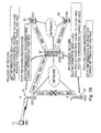
- the setting of the return of the packet is basically reset when the existence of the mobile station at the communication destination cannot be checked. Specifically, as illustrated in Fig. 26 , upon turning-off power of a PDA forming the mobile station 12, the base station 22 that manages the PDA may not check the existence of the mobile station 12. In this case, a Data path De-Registration Request of R6 as an interface between the base station 22 and the ASN-GW 31 is transmitted from the base station 22 to the ASN-GW 31. As a consequence, in the ASN-GW 31, processing for deleting the route management of the corresponding GRE tunnel is caused.
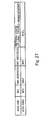
- the ASN-GW 31 deletes the corresponding record on the return management table.
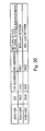
- the return management table becomes a state illustrated in Fig. 27 .
- Fig. 28 is a sequence diagram illustrating a flow of the operation of the communication system according to the third embodiment.
- the base station 22 for managing the mobile station 12 transmits the DataPath De-Registration Request to the ASN-GW 31.
- the ASN-GW 31 resets the corresponding communication path between the ASN-GW 31 and the base station 22 (S112).
- the return management table is checked (S113).
- the corresponding record is deleted and the return management table is updated (S114).
- Information for deleting the corresponding NAT information and routing information is created so that the base stations 21 and 22 reset the setting of the return of the corresponding packet, and is then transmitted to the base stations 21 and 22.
- the base stations 21 and 22 that receive the information reset the setting of a path (i.e., path for directly transferring the corresponding packet) for returning the packet between the base stations 21 and 22 (S115 and S118).
- the base stations 21 and 22 delete the corresponding NAT information and routing information (S116 and S119).
- the corresponding packet (packet of the communication between the mobile station 11 and the mobile station 12) is deleted from the target of the return of the packet (S117 and S120).
- the communication system includes processing for setting the return of the packet (S21 to S25 in Fig. 15 and in S91 to S99 in Fig. 23 ) and executing the handover of one of the mobile stations.
- the handover means processing in which, when the mobile station is moved out of a cell managed by the base station for managing the mobile station, the base station for managing the mobile station is automatically switched to the base station for managing the cell after the movement.
- the structure according to the fourth embodiment is similar to the structure according to the first or second embodiment, and an overlapped description thereof will be omitted.
- the ASN-GW 31 may have the processing realized according to the three first, second, and fourth embodiments and alternatively may have the processing realized according to the fourth and second embodiments. Alternatively, in any of the cases, the ASN-GW 31 may additionally have the processing according to the third embodiment.
- the mobile station 11 exists under the management of the base station 21, and the mobile station 12 is switched under the management from the base station 22 to the base station 23 with the handover.
- the mobile station 12 transmits Mobile MS Handover Request (hereinafter, simply referred to as MOB_MSHO-REQ) to the base station 23 as the handover destination.
- MOB_MSHO-REQ Mobile MS Handover Request
- the base station 23 that receives the MOB_MSHO-REQ transmits a Handover Request (hereinafter, simply referred to as HO request) to the ASN-GW 31.
- the ASN-GW 31 recognizes the mobile station 12 that transmits the HO request. It is checked by referring to the return management table illustrated in Fig. 30 to see if the return of the packet is set to the mobile station 12.
- the return of the packet is set to the mobile station 12.
- the ASN-GW 31 that checks this resets the setting of the return of the corresponding packet. Then, the sequence of the handover continues. The resetting of the setting of the return of the packet enables the return management table to enter a state illustrated in Fig. 32 .
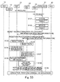
- Fig. 33 is a sequence diagram illustrating the resetting operation of the setting of the return of the packet illustrated in Fig. 31 .
- the HO request is transmitted to the base station 23 as the moving destination from the mobile station 12. Then, the base station 23 transmits the HO request to the ASN-GW 31.
- the ASN-GW 31 refers to the return management table (S131).
- the return of the packet is set to the packet of the communication between the mobile station 12 and the mobile station 11. Therefore, this is updated as illustrated in Fig. 32 (S132). That is, in order to reset the setting of the return of the packet, in the return management table, "Null" is set to a column of the "return state".
- Information for deleting the corresponding NAT information and routing information is created so that the base stations 21 and 22 reset the setting of the return of the corresponding packet, and is then transmitted to the base stations 21 and 22.
- the base stations 21 and 22 that receive the information reset the setting of a path (i.e., path for directly transferring the corresponding packet between the base stations 21 and 22) for returning the packet (S133 and S136).
- the base stations 21 and 22 delete the corresponding NAT information and routing information (S134 and S137).
- the corresponding packet (packet of the communication between the mobile station 11 and the mobile station 12) is deleted from the target of the return of the packet (S135 and S138). Thereafter, the operation of the handover is executed (S139).
- the setting of the return of the packet is reset, and a control operation of the handover is executed by using a packet transfer route via the HA.
- the return adaptation is determined again by checking the amount of transfer packets between the mobile station 11 and the mobile station 12 and the type of protocol.
- the return of the packet is set to the corresponding packet again.
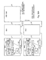
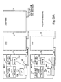
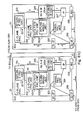
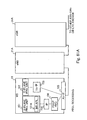
- Fig. 34A is a block diagram illustrating communication apparatus 11, 21, and 31 having the structures as the mobile station 11, base station 21, and ASN-GW 31 according to the first embodiment.
- the base station 21 and the ASN-GW 31 are illustrated in detail in Fig. 34B .
- the communication apparatus 12 for performing the processing of the mobile station 12 has the block structure similar to that of the communication apparatus 11 for performing the processing of the mobile station 11, and an overlapped description thereof will be therefore omitted.
- the communication apparatus 22 for performing the processing of the base station 22 has the block structure similar to that of the communication apparatus 21 for performing the processing of the base station 21, and an overlapped description thereof will be therefore omitted.
- the communication apparatus 32 for performing the processing of the ASN-GW32 has the block structure similar to that of the communication apparatus 31 for performing the processing of the ASN-GW 31, and an overlapped description thereof will be therefore omitted.
- the communication apparatus 11 for performing the processing of the mobile station 11 comprises: a C-Plane processing unit 102; a U-Plane processing unit 101 having an MS APL unit 101A; an R1-IF unit 103; an IP unit 104; and an Air-IF unit 105.
- the C-Plane processing unit 102 performs control processing.
- the U-Plane processing unit 101 performs processing of user data.
- the MS APL unit 101A performs processing of various applications (VoIP, Web browser, email, and the like).
- the R1-IF unit 103 performs processing of R1-interface processing (interface between the mobile station and the base station).
- the IP unit 104 performs IP processing (TCP/IF, UDP/IP, routing processing, and the like).
- the Air-IF unit 105 provides a wireless interface.
- the communication apparatus 21 for performing the processing of the base station 21 comprises: a C-Plane processing unit 201; a U-Plane processing unit 202; an R1-IF unit 203; an R6-IF unit 205; a Tunnel processing unit 204; an IP unit 207; an NIC unit 208; and an Air-IF unit 206.
- the C-Plane processing unit 201 comprises a return IF processing unit 201A.
- the U-Plane processing unit 202 comprises a DataPath processing unit 202A.
- the DataPath processing unit 202A comprises a return management unit 202B.
- the R6-IF unit 205 comprises a return-IF unit 205A.
- the C-Plane processing unit 201 performs control processing.
- the U-Plane processing unit 202 performs processing of the user data.
- the R1-IF unit 203 performs R1-interface processing (interface between the mobile station and the base station).
- the R6-IF unit 205 performs R6-interface processing (interface processing between the base station and the ASN-GW).
- the IP unit 207 performs IP processing (TCP/IF, UDP/IP, routing processing, and the like).
- the Air-IF unit 206 provides a wireless interface.
- the DataPath processing unit 202A performs route management of data transfer.
- the Tunnel processing unit 204 manages the GRE tunnel.
- the NIC unit 208 includes a function as a network interface card (hereinafter, referred to as Network Interface Card).
- the return-IF unit 205A analyzes a return instruction (setting/resetting/path setting/path resetting) obtained by expanding the R6-interface from the ASN-GW.
- the return-IF processing unit 201A transmits the received return instruction to the return management unit 202B.
- the return management unit 202B sets NAT/path/routing in accordance with the return instruction.
- the communication apparatus 31 for performing the processing of the ASN-GW 31 comprises: a C-Plane processing unit 301; a U-Plane processing unit 302; an FA unit 303; a DHCP Proxy unit 304; an R6-IF unit 307; an R4/R3-IF unit 306; a Tunnel processing unit 305; an IP unit 308; and NIC units 309 and 310.
- the C-Plane processing unit 301 comprises a return-IF processing unit 301A.
- the U-Plane processing unit 302 comprises a DataPath processing unit 302A.
- the DataPath processing unit 302A comprises a return management unit 302B.
- the R6-IF unit 307 comprises a return-IF unit 307A.
- the C-Plane processing unit 301 performs control operation.
- the U-Plane processing unit 302 performs processing of the user data.
- the R6-IF unit 307 performs processing of the R6-interface (interface processing between base station and the ASN-GW).
- the IP unit 308 performs IP processing (TCP/IF, UDP/IP, or routing processing).
- the DataPath processing unit 302A performs path management of the data transfer.
- the Tunnel processing unit 305 manages a GRE/MIP tunnel.
- the NIC units 309 and 310 are network interface cards.
- the FA unit 303 performs processing of the FA.
- the R4/R3-IF unit 306 performs processing of R4 (interface between the ASN-GW and another ASN-GW) and R3 (interface between the ASN-GW 31 and an upper-level).
- the return-IF unit 307A constructs and transmits a return instruction message to the base station via the R6 interface.
- the return-IF processing unit 301A issues an instruction to the base station, depending on the return state.
- the return management unit 302A checks the packet and determines the return thereof on the basis of the return management table.
- the basic thinking of the communication system according to the first to fourth embodiments is applied to the 3GPP technology.
- the packet is returned by controlling the transfer path of the packet performed in the base station and the ASN-GW with the WiMAX technology.
- a data processing load of the base station and the ASN-GW is reduced and a load of transmission resources is reduced.
- the packet is returned by packet transfer path control performed by an eNB corresponding to the base station and an aGW corresponding to ASN-GW with the WiMAX technology.
- a data processing load of the eNB and the aGW is reduced and a load of transmission resources is also reduced.
- packet distributing processing is concentrated to the aGW for collecting the communication packets on the fast wireless side, and a machine load is large.
- a communication network under management of the aGW for collecting the communication packets on the fast wireless side usually has a data transfer speed of 1 Gbps. Therefore, as the data transfer speed is faster on the wireless side, the resources run short. Further, the packet communication between the mobile stations performed between a plurality of the aGWs is assumed to have the two problems.
- the aGW monitors the communication state of the mobile station under management of the aGW, and performs the setting for the return of the packet according to the necessity as mentioned above. Further, the eNB sets a transfer path of the packet between the eNBs so as to set the return of the packet from the aGW. Further, upon embodying the handover, the aGW resets the transfer path for returning the packet. The aGW also sets the return of the packet in cooperation with aGW devices in the communication between the mobile stations between a plurality of the aGWs.
- the aGW that manages the eNB checks the destination of the packet from the mobile station such as a PDA.
- the aGW performs, for the eNB device, NAT (i.e., change/replacement of the IP address) processing, structures a tunnel between the eNBs, and instructs the change of the routing table. That is, the transfer path of the packet is changed in the eNB and between the eNBs, and the return of the packet is embodied.
- NAT i.e., change/replacement of the IP address
- the 3GPP system technology and the wireless LAN system (i.e., WiMAX) technology are integrated. Therefore, the main device structure and the processing executed by devices with the 3GPP technology are similar to those with the WiMAX technology.
- interface prescriptions are individually provided for the WiMAX technology and the 3GPP technology. Therefore, a message needs to be added to the following interface (Reference Point) so as to apply the basic thinking of the communication system according to the first to fourth embodiments to the 3GPP technology.
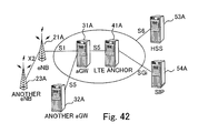
- Fig. 42 at Reference Point X2, a message for establishing a transfer path or resetting the path is added for the return of the packet between the eNBs 21A and 23A.
- Fig. 42 illustrates an example of the Reference Point with the 3GPP technology.
- the following device can be expressed as the following different name.
- the aGW can be also referred to as Serving GW.
- the LTE anchor can be also referred to as PDN (Packet Data Network or Public Data Network) GW.
- PDN Packet Data Network or Public Data Network
- a protocol for compressing the header referred to as PDCP in the 3GPP and performing sequence number management is positioned under a layer of the IP packet. Therefore, when the eNB extracts or creates the IP packet, PDCP information is needed. Therefore, the PDCP information needs to be added to transfer information instructing that the packet is returned from the aGW to the eNB.
- the structure illustrated in Fig. 8 can be used.
- the PDCP is terminated to the eNB and, therefore, the PDCP information does not need to be transferred from the aGW to the eNB.
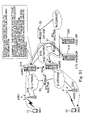
- Fig. 43 illustrates a flow of the packet in the communication between the mobile stations 11 and 12 under management of the eNB.
- a path illustrated by an arrow in the drawing will be sequentially described when the packet is transferred from the mobile station 11 to the mobile station 12.
- the resetting of the PDCP in Item 3) and the setting of the PDCP in Item 5) move to the processing of the eNB 21A in Item 2) and Item 6).
- the PDCP header is not set to the packet between the eNB 21A and the aGW 31A illustrated in Fig. 43 .
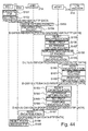
- the mobile station 11 executes the FTP in S151.
- the PDCP is set (S152), and the packet is transferred to the eNB 21A.
- the eNB 21A receives the packet, and then determines whether or not the packet is registered as the target of the return of the packet (S153). It is not determined that the packet is registered as the target of the return of the packet, the packet is encapsulated and the packet is transferred to the aGW 31A as the destination (S154).
- the aGW 31A receives the packet and then resets the encapsulation (S155), and resets the PDCP (S156). Similarly to the first embodiment, the return adaptation determination is embodied (S157). Further, the aGW 31A replaces the destination of the packet from the mobile station 11 to GA 1 (S158), performs the encapsulation (S159), and transfers the packet to the LTE anchor 41A.
- the LTE anchor 41A receives the packet and resets the encapsulation (S160), and performs routing for setting the destination of the packet to the address of the mobile station 12 (S161).
- the encapsulation is performed (S162), and the packet is transferred to the aGW 31A.
- the aGW 31A receives the packet and resets the encapsulation (S163). Similarly, the aGW 31A performs the return adaptation determination (S164), and sets the PDCP (S165). The encapsulation is performed (S166), and the packet is transferred to the eNB 21A.
- the eNB 21A receives the packet, and resets the encapsulation (S167), and transfers the packet to the mobile station 12.
- the mobile station 12 receives the packet, and resets the PDCP (S168), and obtains data of the packet (S169).
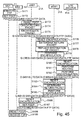
- the mobile station 11 executes the FTP.
- the PDCP is set (S172), and the packet is transferred to the eNB 21A.
- the eNB 21A receives the packet, and resets the PDCP (S173). It is determined whether or not the packet is registered as the target of the return of the packet (S174). It is not determined that the packet is registered as the target of the return of the packet, the packet is encapsulated and the encapsulated packet is transferred to the aGW 31A as the destination (S175).
- the aGW 31A receives the packet and resets the encapsulation (S176). Similarly to Fig. 44 , the return adaptation determination is embodied (S177). Further, the aGW 31A replaces the destination of the packet from the mobile station 11 to GA 1 (S178), performs the encapsulation (S179), and transfers the packet to the LTE anchor 41A.
- the LTE anchor 41A receives the packet and resets the encapsulation (S180), and performs the routing for setting the destination of the packet to the address of the mobile station 12 (S181).
- the encapsulation is performed (S182), and the packet is transferred to the aGW 31A.
- the aGW 31A receives the packet and resets the encapsulation (S183). Similarly, the return adaptation determination is performed (S184), the encapsulation is performed (S185), and the packet is transferred to the eNB 21A.
- the eNB 21A receives the packet, and resets the encapsulation (S186), sets the PDCP (S187), and transfers the packet to the mobile station 12.
- the mobile station 12 receives the packet, resets the PDCP (S188), and obtains data of the packet (S189).
- the aGW 31A Upon transmitting the packet from the aGW 31 A to the LTE anchor 41A and upon receiving the packet from the LTE anchor 41A to the aGW 31A, the destination of the packet or address of the transmission side is checked.
- the address is the IP address, such as GA 1 or GA 2
- the aGW 31A determines whether or not the eNB under management of the aGW 31A performs the return of the packet.
- the aGW 31A has the return management table illustrated in Fig. 46 , as performed by the ASN-GW 31 according to the first embodiment. Thereafter, the aGW 31A analyzes the traffic situation and the protocol (FTP or streaming) of the packet, and performs the return adaptation determination. It is determined that the return of the packet of the communication between the mobile station 11 and 12 is set, the aGW 31A creates the NAT information and routing information for embodying the return of the corresponding packet on the basis of the return management table illustrated in Fig. 46 , similarly to the ASN-GW 31 according to the first embodiment. Further, the return state of the return management table is changed, as illustrated in Fig. 47 . As illustrated in Fig. 48 , an instruction for embodying the return of the packet is issued to the eNB 21A.
- Fig. 49 illustrates the operation for instructing the return of the packet and the subsequent operation sequence of the packet transfer from the mobile station 11 to the mobile station 12.
- the aGW 31A performs the return adaptation determination. If it is determined that the packet under a predetermined condition (destination and transmission source) is to be registered as the target of the return of the packet (S201), the return management table is updated. In this case, with respect to the packet of the communication between the mobile station 11 and the mobile station 12, "return to MS 2" and “return to MS 1" are written to a return state column of the corresponding record as illustrated in Fig. 47 (S202). Further, the aGW 31A creates the NAT information and routing information necessary for embodying the return of the packet by the eNB 21A, and transmits the information to the eNB 21A (S203).
- the eNB 21A that receives the information sets the NAT information and routing information to the eNB 21A (S204), and registers the corresponding packet of the communication between the mobile station 11 and the mobile station 12 as the target of the return of the packet (S205).
- the mobile station 11 performs the FTP processing (S206), and further sets the PDCP (S207).
- the packet addressed to the mobile station 12 is transferred to the eNB 21A.
- the eNB 21A checks to see if the packet is registered as the target of the return of the packet (S208). The packet matches the condition (destination and transmission source) registered in S205. Therefore, the NAT processing and routine processing for returning the packet is performed (S209). As a consequence, the eNB 21A replaces the destination address of the packet to the address of the mobile station 12, and replaces the address on the transmission source to GA 1 of the mobile station 11. As a consequence, the return of the packet is embodied, and the packet is directly transferred to the mobile station 12.
- the mobile station 12 receives the packet and resets the PDCP (S212), and obtains data of the packet (S213).
- the packet from the mobile station 11 is returned by the NAT processing and routine processing for returning the packet in the eNB 21A, and is directly transferred to the mobile station 12.
- the PDCP information does not need to be transferred upon transferring information having an instruction indicating that the return of the packet is performed from the aGW 31A to the eNB 21A or the setting thereof is reset. Thereafter, the setting of the PDCP information is not necessary.
- the communication system according to the sixth embodiment has the same structure as that of the communication system according to the fifth embodiment.
- the mobile station 11 as the transfer source of the packet and the mobile station 12 as the transfer destination are respectively managed by the aGWs 31A and 32A, unlike the fifth embodiment.
- the communication system i.e., the communication system with the WiMAX technology
- an operation for searching the mobile stations managed by all ASN-GWs from the IP addresses can have a high load. Therefore, the execution of the return of the packet is limited within the managing range of the ASN-GW.
- the address of the mobile station under which of the aGW or eNB can be searched from the IP address of the packet with a low load the limiting of the execution range is not necessary. That is, the return of the packet can be also embodied for the communication between the mobile stations via a plurality of the aGWs.
- two specific methods for realizing this will be sequentially described.
- E-UTRANs (hereinafter, referred to as Evolved Universal Terrestrial Radio Access Network) under management of a plurality of the aGWs are mutually connected thereto, thereby performing the cooperation of the plurality of the aGWs.
- Fig. 50 illustrates a flow of the packet with the first method.
- a router 55 mutually connects an E-UTRAN (E-UTRAN 1) under management of the aGW 31A and an E-UTRAN (E-UTRAN 2) under management of the aGW 32A.
- E-UTRAN 1 E-UTRAN 1
- E-UTRAN 2 E-UTRAN 2
- the cooperation between the aGWs 31A and 32A is established and this enables reception and transmission of information indicating an instruction of the return of the packet or an instruction of the resetting of the setting between the aGWs 31A and 32A.
- a tunnel for embodying the return of the packet can be structured between the eNB 21A and the eNB 22A, the packet can be transferred via the tunnel.
- the second method performs specification from the IP address of the packet by using a low load at the position of the aGW or eNB for managing the corresponding mobile station.
- the aGW 31A determines whether or not the packet addressed to the mobile station 12 is a local one.
- the aGW 31A specifies the position of the mobile station (i.e., determines whether or not the mobile station 12 is under management of the eNB 22 of the aGW 32A) from the destination IP address of the packet that is in progress of the transfer with a lower load as much as possible.
- the following third method and fourth method are considered.
- the third method is as follows.
- the position of the aGW for managing the mobile station is obtained from user information management database such as HSS. That is, with the HSS (corresponding to HA or AAA in the case of the WiMAX technology), the structure is provided to manage the correspondence between the IP address and the aGW/eNB.
- the position of the aGW/eNB for managing the corresponding mobile station is obtained from the IP address of the packet on the basis of the correspondence.
- the method can be realized by expanding an interface of Reference Point S6 illustrated in Fig. 42 .
- the fourth method is as follows. That is, a specific packet to the mobile station is transmitted. As illustrated in Fig. 51 , an echo request is transmitted to the IP address of the mobile station 12 relayed by the aGW 31A.
- the echo request means that the expanded packet such as ICMP is transmitted to the aGW 32A side as a partner.
- the corresponding aGW information and eNB information is transmitted as an echo response to the request of the aGW 32A.
- the aGW 31A refers to the aGW information and eNB information, thereby specifying the aGW 32A and the eNB 22A for managing the mobile station 12 of the IP address.
- Fig. 52 illustrates the case of the communication between the mobile stations 11 and 12 under management of the aGWs 31A and 32A different from each other. A description will be given of the case of transferring the packet from the mobile station 11 to the mobile station 12 along a path illustrated by an arrow in Fig. 52 .
- the PDCP resetting processing in Item 3) and the PDCP setting processing in Item 5) move to the processing of the eNB 21A in Item 2) and Item 6), respectively.
- the PDCP header is not set to the packet for transfer between the eNB 21A and the aGW 31A.
- the mobile station 11 executes the FTP.
- the PDCP is set (S222), and the packet is transferred to the eNB 21A.
- the eNB 21A receives the packet, and determines whether or not the packet is registered as the target of the return of the packet (S223). When it is not determined that the packet is registered as the target of the return of the packet, the packet is encapsulated and the packet is transferred to the aGW 31A as the destination (S224).
- the aGW 31A receives the packet and resets the encapsulation (S225), and resets the PDCP (S226). Similarly to the fifth embodiment, the return adaptation determination is embodied (S227).
- the aGW 31A replaces the destination of the packet from the mobile station 11 to GA 1 (S228), performs the encapsulation (S229), and transfers the packet to the LTE anchor 41A.
- the LTE anchor 41A receives the packet and resets the encapsulation (S230), and performs routing for setting the destination of the packet as the address of the mobile station 12 (S231).
- the encapsulation is performed (S232), and the packet is transferred to the aGW 32A.
- the aGW 32A receives the packet and resets the encapsulation (S233). Similarly, the aGW 32A performs the return adaptation determination (S234), and sets the PDCP (S235). The aGW 32A performs the encapsulation (S236), and transfers the packet to the eNB 22A managed thereby.
- the eNB 22A receives the packet and resets the encapsulation (S237), and transfers the packet to the mobile station 12 that manages it.
- the mobile station 12 receives the packet and resets the PDCP (S238), and obtains data of the packet (S239).
- the mobile station 11 executes the FTP.
- the PDCP is set (S252), and the packet is transferred to the eNB 21A.
- the eNB 21A receives the packet and resets the PDCP (S253). It is determined whether or not the packet is registered as the target of the return of the packet (S254). It is not determined that the packet is registered as the target of the return of the packet, the packet is encapsulated, and the packet is transferred to the aGW 31A as the destination (S255).
- the aGW 31A receives the packet and resets the encapsulation (S256). Similarly to the case illustrated in Fig. 53 , the return adaptation determination is embodied (S257).
- the aGW 31A replaces the destination of the packet from the mobile station 11 to the GA 1 (S258), performs the encapsulation (S259), and transfers the packet to the LTE anchor 41A.
- the LTE anchor 41A receives the packet and resets the encapsulation (S260), and performs routing for setting the destination of the packet to the address of the mobile station 12 (S261).
- the encapsulation is performed (S262), and the packet is transferred to the aGW 32A.
- the aGW 32A receives the packet and resets the encapsulation (S263), similarly performs the return adaptation determination (S264), performs encapsulation (S265), and transfers the packet to the eNB 22A managed thereby.
- the eNB 22A receives the packet and resets the encapsulation (S266), sets the PDCP (S267), and transfers the packet to the mobile station 12 that manages it.
- the mobile station 12 receives the packet and resets the PDCP (S268), and obtains data of the packet (S269).
- the destination of the packet and the address on the transmission side are checked.
- the address is the IP address, such as GA 1 or GA 2
- the packet is returned by the eNB under management of the aGW.
- the aGW 31A and the aGW 32A manage the return management table illustrated in Figs. 55 and 56 , respectively. Thereafter, the aGW 31A or aGW 32A analyzes the traffic situation and the protocol (FTP or streaming) of the packet, and performs the return adaptation determination of the corresponding packet. When it is determined that the packet of the communication between the mobile stations 11 and 12 is to be registered as the target of the return of the packet, the aGW 31A and the aGW 32A search the mobile stations 11 and 12 for the communication of the corresponding packet with the third method or fourth method. As a consequence, the eNB and the aGW for managing the mobile station on the partner side are specified.
- the aGW 31A and the aGW 32A as specified above are cooperated and the return management table illustrated in Figs. 55 and 56 is updated. Further, the aGW 31A and the aGW 32A create the NAT information and routing information for embodying the return of the packet on the basis of the return management table. As illustrated in Fig. 59 , an instruction for embodying the return of the packet is issued to the eNB 21A and the eNB 22A under management thereof.
- Figs. 60A and 60B illustrate an operation sequence of an example of an operation for instructing that the return of the packet is executed and a subsequent packet-transfer operation from the mobile station 12 to the mobile station 12 in the communication system according to the sixth embodiment.
- the aGW 31A performs the return adaptation determination (S281). Further, the eNB and the aGW on the mutual partner side are specified by using the third method (S282) or fourth method (S283). It is determined that the packet of the communication between the mobile stations 11 and 12 is to be registered as the target of the return of the packet, the aGW 31A is cooperated with the aGW 32A, and the return management table is updated (S284 and S286). That is, as illustrated in Figs. 57 and 58 , with respect to the packet of the communication between the mobile station 11 and the mobile station 12, "return to MS 2" and "return to MS 1" are written to a return state column of the corresponding record.
- the aGW 31A and the aGW 32A create the NAT information and routing information necessary for embodying the return of the packet by the eNB 21A and the eNB 21B managed thereby and transfer the information to the eNB 21A and the eNB 21B (S285 and S287).
- the eNBs 21B and 22B that receive the packet set a path (i.e., path for directly transferring the corresponding packet between the eNBs 21A and 22A) for returning the packet thereto (S288 and S289).
- the information is exchanged so as to check the path for returning the packet between the eNBs 21A and 22B ("check return path" in the drawing).
- the eNBs 21B and 22B set the NAT information and routing information thereto (S290 and S292).
- the packet of the communication between the mobile station 11 and the mobile station 12 is registered as the target of the return of the packet (S291 and S293).
- the mobile station 11 performs the FTP processing (S294), sets the PDCP (S295), and transfers the packet addressed to the mobile station 12 to the eNB 21A.
- the eNB 21A receives the packet and resets the PDCP of the packet (S296). It is checked to see if the packet is registered as the return target (S297).
- the packet is encapsulated (S298). Since the packet matches the condition (destination and transmission source) registered in S291 as a result of S297, the NAT processing and routine processing are performed for returning the packet (S299). That is, the eNB 21A sets the destination of the packet as the address of the eNB 22A, and the transmission side is set as the address of the eNB 21A.
- the address on the transmission source of the internal header of the encapsulated packet is replaced to the global address GA 1 of the mobile station 11.
- the packet is transferred to the eNB 22A, and the eNB 22A resets the encapsulation (S300). Since the packet matches the condition (destination and transmission source) registered in S293, the NAT processing and routine processing for returning the packet are performed (S301). That is, the destination of the packet address is replaced to the address of the mobile station 12.
- the return of the packet is embodied, and the packet is returned by the eNBs 21A and 22B and is transferred to the mobile station 12.
- the mobile station 12 that receives the packet resets the PDCP of the packet (S303), and obtains data of the packet in the FTP receiving processing (S304).
- the PDCP information does not need to be set to the return instruction information from the aGW to the eNB.
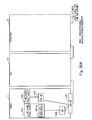
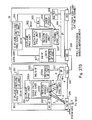
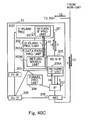
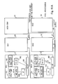
- Figs. 61A and 61B are block diagrams illustrating a block structure of the communication apparatus 11 illustrated in detail in Fig. 61A , communication apparatus 21A, and communication apparatus 31A that are illustrated in detail in Fig. 61B and perform the processing of the mobile station 11, eNB 21A, and aGW 31A structuring the fifth and sixth embodiments.
- the communication apparatus 21A, and the communication apparatus 31A are illustrated in detail in Fig. 61B .
- a communication apparatus 12 that executes the processing of the mobile station 12 has the same block structure as that of a communication apparatus 11 that executes the processing of the mobile station 11, and an overlapped description thereof will be therefore omitted.
- a communication apparatus 22A for executing the processing of the eNB 22A has the same block structure as that of a communication apparatus 21A for executing the processing of the eNB21A and an overlapped description thereof will be therefore omitted.
- a communication apparatus 32A for executing the processing of the aGW 32A has the same block structure as that of the communication apparatus 31A for executing the processing of the aGW 31A and an overlapped description thereof will be therefore omitted.
- a communication apparatus 11 for executing the processing of the mobile station 11 comprises: the U-Plane processing unit 101 having the MS APL unit 101A; the C-Plane processing unit 102; the Un-IF unit 103; the IP unit 104; the PDCP processing unit 106; and the Air-IF unit 105.
- the Control Plane unit 102 executes control processing, and the U-Plane processing unit 101 performs processing of user data.
- the MS APL unit 101A performs processing of various application (VoIP, Web browser, and email).
- the Uu-IF unit performs processing of an interface of LTE-Uu interface processing, i.e., at the wireless interval between the mobile station and the eNB.
- the IP unit 104 performs IP processing, i.e., TCP/IF, UDP/IP, and routing processing.
- the Air-IF unit 105 is a wireless interface.
- the communication apparatus 21A that executes the processing of the eNB 21A comprises: the C-Plane processing unit 201 including the return IF processing unit 201A; and a U-Plane processing unit 202 including a Bearer management unit 202C having a return management unit 202D. Further, the communication apparatus 21A comprises: an S1/X2-IF unit 213 having a return-IF unit 213A; a GRE/GTP-U processing unit 212; a Uu-IF unit 211; the IP unit 207; the PDCP processing unit 209; the Air-IF unit 206; and the NIC unit 208.
- the Control Plane unit 201 (C-Plane unit 201) executes control processing, and the U-Plane processing unit 202 performs processing of user data.
- the Uu-IF unit 211 performs the processing of an interface of an LTE-Uu interface processing, i.e., at the wireless interval between the mobile station and the eNB.
- the IP unit 207 performs IP processing, i.e., TCP/IF, UDP/IP, and routing processing.
- the Air-IF unit 206 is a wireless interface.
- the Bearer management unit 202C performs route management of data transfer.
- the GRE/GTP-U processing unit performs the GRE tunnel or GTP-U tunnel.
- An S1/X1-IF unit performs processing of an interface of S1 (i.e., between the eNB and the aGW) and X2 (i.e., between the eNBs).
- the NIC unit 208 is a network interface card.
- the PDCP processing unit 209 performs processing for working the IP packet, compressing the header, and managing the sequence number.
- the return-IF unit 213A analyzes a return instruction (setting/resetting/path setting/path resetting) as the expanded S1, obtained by the aGW.
- the return-IF processing unit 201A transmits the received return instruction to the return management unit 202D.
- the return management unit 202D sets NAT/path/routing/PDCP in response to a return instruction.
- the communication apparatus 31A for executing the processing of the aGW 31A comprises the C-Plane processing unit 301 (Control Plane unit 301) including the return-IF processing unit 301A and an inter-aGW cooperation IF processing unit 301B. Further, the communication apparatus 31A comprises the U-Plane processing unit 302 including the Bearer management unit 302C having a return management unit 304D and an MS search processing unit 302E. Furthermore, the communication apparatus 31A comprises: an S1-IF unit 317 having a return-IF unit 317A; and an S6/S5-IF unit 316 having an MS search processing unit 316A. In addition, the communication apparatus 31A comprises: the PDCP processing unit 313; the GTP-U processing unit 314; the GRE/GTP-U processing unit 315; the IP units 311 and 312; and the NIC units 309 and 310.
- the C-Plane processing unit 301 executes the control processing, and the U-Plane processing unit 302 performs processing of user data.
- the IP units 311 and 312 perform IP processing, i.e., TCP/I/F, UDP/IP, and routing processing.
- the Bearer management unit 302C performs route management of the data transfer.
- the GRE/GTP-U processing unit 315 manages the GRE tunnel or GTP-U tunnel.
- the NIC units 309 and 310 are network interface cards.
- the PDCP processing unit 313 performs processing for working the IP packet, compressing the header, and managing the sequence number.
- the S6/S5-IF unit 316 performs processing of an interface via S5 (i.e., between the aGWs or between the aGW and the LTE anchor) and S6 (i.e., between the aGW and HSS).
- the return-IF unit 317A constructs a return instruction message and transmits the created message to the eNB via an S1 interface.
- the IF processing unit 301A issues an instruction to the eNB, depending on the return state.
- the return management unit 302D checks the packet and determines the return on the basis of the return management table.
- the inter-aGW cooperation IF processing unit 301B performs processing of an interface when the aGWs cooperates with each other with respect to the return information.
- the MS search processing unit 316A requests information on the positions of the aGW and the eNB for managing the mobile stations in the mutual communication to HSS, or constructs a response message in response to the request.
- the MS search processing unit 302E expands an ICMP packet, and transmits or receives a message for specifying the information on the positions of the aGW and the eNB for managing the mobile stations in the mutual communication.
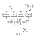
- Fig. 62 is a block diagram of computer hardware for explaining the case of realizing the devices forming the communication system according to the embodiments.
- the communication systems means the communication apparatus 11, 12, 21, 22, 31, 32, 21A, 22A, 31A, and 32A that execute processing of the mobile station 11 and 12, the base stations 21 and 22, the ASN-GWs 31 and 32, the eNBs 21A and 22A, and the aGWs 31A and 32A.
- a computer 500 comprises: a CPU 501 that performs various operations by executing a command structuring a given program; an operation unit 502 that inputs operation contents or data by user via a keyboard or mouse; a display unit 503, such as a CRT or liquid crystal display, that displays a processing progress and a processing result of the CPU 501 to a user; a memory 504, such as a ROM or RAM, that stores a program and data executed by the CPU 501 and is used as a work area; a hard disk device 505 that stores the program and data; a CD-ROM drive 506 that loads the program or loads the data from an external unit via a CD-ROM 507; and a modem 508 that downloads the program from an external unit via a communication network 509 such as Internet or LAN.
- a communication network 509 such as Internet or LAN.
- the computer 500 loads or downloads the program via the CD-ROM 507 or via the communication network 509.
- the program includes commands for enabling the CPU 501 to execute the processing performed by the communication apparatuses 11, 12, 21, 22, 31, 32, 21A, 22A, 31A, and 32A.
- the computer 500 installs the program to the hard disk device 505 and properly loads the program to the memory 504, and the CPU 501 executes the program.
- the computer 500 realizes the communication apparatuses 11, 12, 21, 22, 31, 32, 21A, 22A, 31A, and 32A.
Landscapes
- Engineering & Computer Science (AREA)
- Databases & Information Systems (AREA)
- Computer Networks & Wireless Communication (AREA)
- Signal Processing (AREA)
- Mobile Radio Communication Systems (AREA)
Applications Claiming Priority (1)
| Application Number | Priority Date | Filing Date | Title |
|---|---|---|---|
| JP2008074305A JP5169360B2 (ja) | 2008-03-21 | 2008-03-21 | 通信装置、及び通信装置の制御方法 |
Publications (2)
| Publication Number | Publication Date |
|---|---|
| EP2111072A2 true EP2111072A2 (fr) | 2009-10-21 |
| EP2111072A3 EP2111072A3 (fr) | 2012-06-06 |
Family
ID=41050890
Family Applications (1)
| Application Number | Title | Priority Date | Filing Date |
|---|---|---|---|
| EP09155514A Withdrawn EP2111072A3 (fr) | 2008-03-21 | 2009-03-18 | Appareil de communication et procédé pour la commande de l'appareil de communication |
Country Status (3)
| Country | Link |
|---|---|
| US (1) | US8396048B2 (fr) |
| EP (1) | EP2111072A3 (fr) |
| JP (1) | JP5169360B2 (fr) |
Cited By (1)
| Publication number | Priority date | Publication date | Assignee | Title |
|---|---|---|---|---|
| WO2011076115A1 (fr) * | 2009-12-25 | 2011-06-30 | 华为技术有限公司 | Procédé de transmission de données, station de base et système de transmission de données |
Families Citing this family (12)
| Publication number | Priority date | Publication date | Assignee | Title |
|---|---|---|---|---|
| WO2009046737A1 (fr) * | 2007-10-09 | 2009-04-16 | Telefonaktiebolaget Lm Ericsson (Publ) | Technique pour fournir un support pour une pluralité de protocoles de gestion de mobilité |
| US20110110289A1 (en) * | 2009-11-06 | 2011-05-12 | Muthaiah Venkatachalam | Distributed control architecture for relays in broadband wireless networks |
| US20110134826A1 (en) * | 2009-12-04 | 2011-06-09 | Xiangying Yang | Relay data path architecture for a wireless network |
| IL218046B (en) * | 2012-02-12 | 2018-11-29 | Elta Systems Ltd | An architecture for a multi-directional relay and the devices and methods of operation useful by the way |
| JP5708246B2 (ja) * | 2011-05-25 | 2015-04-30 | 富士通株式会社 | 通信システム、ネットワーク装置、ゲートウエイ装置、コンピュータプログラム、データ送信方法及びデータ転送方法 |
| JP5712085B2 (ja) | 2011-08-25 | 2015-05-07 | 株式会社日立製作所 | ローカルルーティングノード |
| US9301153B2 (en) | 2011-09-28 | 2016-03-29 | Kyocera Corporation | Radio relay apparatus, communication control method thereof, and communication system |
| US9167438B2 (en) * | 2012-08-31 | 2015-10-20 | International Business Machines Corporation | Mobility detection for edge applications in wireless communication networks |
| US10057838B2 (en) * | 2013-04-26 | 2018-08-21 | Qualcomm Incorporated | X2 setup and routing at an X2-gateway |
| CN107409342B (zh) * | 2015-02-23 | 2020-12-29 | 富士通株式会社 | 无线通信系统、通信装置、终端和基站 |
| WO2016185531A1 (fr) * | 2015-05-15 | 2016-11-24 | 富士通株式会社 | Système de communication sans fil, dispositif de communication sans fil, et procédé de commande de transfert |
| JP7388691B2 (ja) * | 2019-09-30 | 2023-11-29 | 株式会社closip | 通信システム及び通信制御方法 |
Family Cites Families (9)
| Publication number | Priority date | Publication date | Assignee | Title |
|---|---|---|---|---|
| JP3895888B2 (ja) * | 1999-06-29 | 2007-03-22 | 株式会社日立製作所 | パケット通信方法およびノード装置 |
| JP3738737B2 (ja) * | 2002-03-04 | 2006-01-25 | 日本電気株式会社 | 通信システムおよび移動端末間通信方法 |
| JP4238086B2 (ja) * | 2003-08-06 | 2009-03-11 | 株式会社エヌ・ティ・ティ・ドコモ | パケット転送制御方法、経路制御装置、フロー処理制御装置、端末管理装置、転送装置、処理サーバ装置、端末装置及びパケット転送システム |
| JP4071700B2 (ja) * | 2003-11-07 | 2008-04-02 | 株式会社エヌ・ティ・ティ・ドコモ | 移動通信システム、内線送受信装置、無線基地局装置、無線制御装置及び移動交換局 |
| JP4453458B2 (ja) * | 2004-06-23 | 2010-04-21 | 日本電気株式会社 | 移動通信ネットワーク、コアネットワーク及びそれに用いる無線アクセス網内ユーザプレーンパス設定方法 |
| US7843871B2 (en) * | 2004-12-21 | 2010-11-30 | International Business Machines Corporation | Method of reestablishing communication by a mobile node upon recovery from an abrupt shut down |
| JP2006211614A (ja) * | 2005-01-31 | 2006-08-10 | Mitsubishi Electric Corp | 無線通信システムおよび基地局 |
| JP4470770B2 (ja) | 2005-03-17 | 2010-06-02 | 日本電気株式会社 | 移動通信制御方法、移動通信システム、ルーティング装置及びプログラム |
| JP4965646B2 (ja) * | 2006-04-17 | 2012-07-04 | シスコ テクノロジー インコーポレーテッド | トラフィックのローカライゼーションのためのシステム及び方法 |
-
2008
- 2008-03-21 JP JP2008074305A patent/JP5169360B2/ja not_active Expired - Fee Related
-
2009
- 2009-03-17 US US12/405,470 patent/US8396048B2/en not_active Expired - Fee Related
- 2009-03-18 EP EP09155514A patent/EP2111072A3/fr not_active Withdrawn
Non-Patent Citations (1)
| Title |
|---|
| None * |
Cited By (1)
| Publication number | Priority date | Publication date | Assignee | Title |
|---|---|---|---|---|
| WO2011076115A1 (fr) * | 2009-12-25 | 2011-06-30 | 华为技术有限公司 | Procédé de transmission de données, station de base et système de transmission de données |
Also Published As
| Publication number | Publication date |
|---|---|
| JP5169360B2 (ja) | 2013-03-27 |
| US20090238115A1 (en) | 2009-09-24 |
| EP2111072A3 (fr) | 2012-06-06 |
| US8396048B2 (en) | 2013-03-12 |
| JP2009232106A (ja) | 2009-10-08 |
Similar Documents
| Publication | Publication Date | Title |
|---|---|---|
| EP2111072A2 (fr) | Appareil de communication et procédé pour la commande de l'appareil de communication | |
| CA2310783C (fr) | Interreseautage ip entre reseau scp et stations mobiles | |
| EP2924956B1 (fr) | Procédé et appareil de transfert entre des serveurs de contenu pour une optimisation du trajet de transmission | |
| US9042339B2 (en) | System and method for supporting robust header compression in wireless communication system | |
| US20050083885A1 (en) | Movement detection method and a mobile terminal | |
| Cominardi et al. | Distributed mobility management solutions for next mobile network architectures | |
| EP1856940A1 (fr) | Fourniture d'informations de protocole de gestion de mobilite a un terminal mobile pour effectuer un transfert dans un systeme de communication mobile | |
| US20100172294A1 (en) | Communication system, control apparatus and router using network-based ip mobility protocol and communication method for the same | |
| US20060056369A1 (en) | Communication system, server, router, and mobile communications terminal | |
| JP4510814B2 (ja) | アクセスネットワークシステム、接続局装置、無線基地局装置、及びパケットロス低減方法 | |
| US20090279452A1 (en) | Hierarchical mobility management system, access router, anchor node, mobile communication system and route setting method | |
| Piri et al. | IEEE 802.21: media independent handover services | |
| JP4902634B2 (ja) | 移動通信システムにおけるハンドオーバーのための移動性管理プロトコル情報の移動端末への提供方法 | |
| JP2002344479A (ja) | モバイルipのデータ転送方法 | |
| KR100922581B1 (ko) | 이동 단말에서의 다중 무선 인터페이스를 이용한 끊김 없는이동성 지원 방법 및 장치 | |
| CN101199169A (zh) | 交叉节点检测方法及利用计算机执行该方法用的交叉节点检测用的程序 | |
| JP2009200864A (ja) | 通信試験装置、方法、およびプログラム | |
| Hussain et al. | Design, implementation and experimental evaluation of an end-to-end vertical handover scheme on NCTUns simulator | |
| US20100272016A1 (en) | Method for supporting transport network independent ip mobility in mobile terminal and system thereof | |
| KR101293303B1 (ko) | 이기종 네트워크 기반 데이터 동시 전송 서비스 시스템 및 그 방법 | |
| KR20070042034A (ko) | 전송계층에서 패스트핸드오버 지원방법 | |
| Melia | IP Converged Heterogeneous Mobility in 4G networks-Network-side Handover Management Strategies | |
| JP2005079804A (ja) | 無線通信端末及びホームエージェント装置 | |
| JP2004235907A (ja) | 移動体通信システム、プログラム、記録媒体および移動体通信方法 | |
| Tantayakul | Mobility Management in New Internet Architectures |
Legal Events
| Date | Code | Title | Description |
|---|---|---|---|
| PUAI | Public reference made under article 153(3) epc to a published international application that has entered the european phase |
Free format text: ORIGINAL CODE: 0009012 |
|
| AK | Designated contracting states |
Kind code of ref document: A2 Designated state(s): AT BE BG CH CY CZ DE DK EE ES FI FR GB GR HR HU IE IS IT LI LT LU LV MC MK MT NL NO PL PT RO SE SI SK TR |
|
| AX | Request for extension of the european patent |
Extension state: AL BA RS |
|
| PUAL | Search report despatched |
Free format text: ORIGINAL CODE: 0009013 |
|
| AK | Designated contracting states |
Kind code of ref document: A3 Designated state(s): AT BE BG CH CY CZ DE DK EE ES FI FR GB GR HR HU IE IS IT LI LT LU LV MC MK MT NL NO PL PT RO SE SI SK TR |
|
| AX | Request for extension of the european patent |
Extension state: AL BA RS |
|
| RIC1 | Information provided on ipc code assigned before grant |
Ipc: H04W 36/00 20090101AFI20120503BHEP Ipc: H04W 80/04 20090101ALN20120503BHEP Ipc: H04W 8/08 20090101ALI20120503BHEP |
|
| 17P | Request for examination filed |
Effective date: 20121203 |
|
| AKX | Designation fees paid |
Designated state(s): DE FR GB |
|
| 17Q | First examination report despatched |
Effective date: 20150710 |
|
| GRAP | Despatch of communication of intention to grant a patent |
Free format text: ORIGINAL CODE: EPIDOSNIGR1 |
|
| STAA | Information on the status of an ep patent application or granted ep patent |
Free format text: STATUS: GRANT OF PATENT IS INTENDED |
|
| RIC1 | Information provided on ipc code assigned before grant |
Ipc: H04W 36/00 20090101ALI20180529BHEP Ipc: H04W 80/04 20090101ALN20180529BHEP Ipc: H04W 8/08 20090101AFI20180529BHEP |
|
| INTG | Intention to grant announced |
Effective date: 20180614 |
|
| STAA | Information on the status of an ep patent application or granted ep patent |
Free format text: STATUS: THE APPLICATION IS DEEMED TO BE WITHDRAWN |
|
| 18D | Application deemed to be withdrawn |
Effective date: 20181025 |