EP2111084A1 - Stroboskopische Hochdruckendladungslampe - Google Patents
Stroboskopische Hochdruckendladungslampe Download PDFInfo
- Publication number
- EP2111084A1 EP2111084A1 EP09155835A EP09155835A EP2111084A1 EP 2111084 A1 EP2111084 A1 EP 2111084A1 EP 09155835 A EP09155835 A EP 09155835A EP 09155835 A EP09155835 A EP 09155835A EP 2111084 A1 EP2111084 A1 EP 2111084A1
- Authority
- EP
- European Patent Office
- Prior art keywords
- polarity
- power
- lamp
- run
- period
- Prior art date
- Legal status (The legal status is an assumption and is not a legal conclusion. Google has not performed a legal analysis and makes no representation as to the accuracy of the status listed.)
- Granted
Links
Images

Classifications
-
- H—ELECTRICITY
- H05—ELECTRIC TECHNIQUES NOT OTHERWISE PROVIDED FOR
- H05B—ELECTRIC HEATING; ELECTRIC LIGHT SOURCES NOT OTHERWISE PROVIDED FOR; CIRCUIT ARRANGEMENTS FOR ELECTRIC LIGHT SOURCES, IN GENERAL
- H05B41/00—Circuit arrangements or apparatus for igniting or operating discharge lamps
- H05B41/14—Circuit arrangements
- H05B41/26—Circuit arrangements in which the lamp is fed by power derived from DC by means of a converter, e.g. by high-voltage DC
- H05B41/28—Circuit arrangements in which the lamp is fed by power derived from DC by means of a converter, e.g. by high-voltage DC using static converters
- H05B41/288—Circuit arrangements in which the lamp is fed by power derived from DC by means of a converter, e.g. by high-voltage DC using static converters with semiconductor devices and specially adapted for lamps without preheating electrodes, e.g. for high-intensity discharge lamps, high-pressure mercury or sodium lamps or low-pressure sodium lamps
- H05B41/2885—Static converters especially adapted therefor; Control thereof
- H05B41/2887—Static converters especially adapted therefor; Control thereof characterised by a controllable bridge in the final stage
-
- Y—GENERAL TAGGING OF NEW TECHNOLOGICAL DEVELOPMENTS; GENERAL TAGGING OF CROSS-SECTIONAL TECHNOLOGIES SPANNING OVER SEVERAL SECTIONS OF THE IPC; TECHNICAL SUBJECTS COVERED BY FORMER USPC CROSS-REFERENCE ART COLLECTIONS [XRACs] AND DIGESTS
- Y02—TECHNOLOGIES OR APPLICATIONS FOR MITIGATION OR ADAPTATION AGAINST CLIMATE CHANGE
- Y02B—CLIMATE CHANGE MITIGATION TECHNOLOGIES RELATED TO BUILDINGS, e.g. HOUSING, HOUSE APPLIANCES OR RELATED END-USER APPLICATIONS
- Y02B20/00—Energy efficient lighting technologies, e.g. halogen lamps or gas discharge lamps
Definitions
- the present invention relates to high intensity discharge (HID) lamps and, more particularly, to an HID strobe lamp and a method for operating an HID strobe lamp.
- HID high intensity discharge
- HID high intensity discharge
- a sealed quartz-glass or ceramic capsule known as a discharge tube, arc tube or burner
- Free electrons in the arc collide with the metal atoms in the vapor exciting electrons of the metal atoms to a higher energy state.
- electromagnetic radiation is emitted having a wavelength determined by the energy level of the electrons and the constituency of the vapor in the capsule.
- HID lighting typically produces light more efficiently and with a color temperature more closely approximating that of sunlight.
- HID lighting has been adapted to many residential and commercial uses, including building, street and sports arena lighting, automotive lighting and aviation lighting.
- the operating characteristics of HID lamps detract from the usefulness of the lamps as stroboscopic light sources.
- an HID lamp does not immediately illuminate when the power is supplied to the lamp.
- a voltage is applied to the electrodes of an HID lamp, there is an initial delay while the gas is heated during which the lamp acts as an open circuit.
- the gas in the discharge tube is ionized with a high voltage pulse, commonly 2-20 kilovolts (kV), enabling the ionized gas to conduct a relatively high current between the lamp's electrodes and producing a glow discharge.
- kV kilovolts
- HID lamps are typically operated with an alternating current of 45 - 225v and a frequency commonly in the range of 150 - 400 Hertz (Hz). The alternating polarity of the current reduces loss of material from the electrodes and the relatively low frequency avoids acoustic resonance which can cause the lamp to flicker, extinguish or even self-destruct.
- an HID lamp may require from 10 seconds to 15 minutes to reach steady state operation and full light output from a cold start.
- Some HID lamps have a "hot restrike" capability enabling restriking of the lamp before the lamp has cooled. Hot restriking typically requires an electrical pulse with 10 times the voltage required for a cold start of the lamp and may adversely effect the lamp's life.
- an HID lamp can be dimmed by reducing the power to the lamp, reducing the power and the output of the lamp to less than about 60% of rated levels runs the risk that the lamp may extinguish requiring a restrike.
- the discharge arc becomes unstable with each change in polarity of the alternating current producing undesirable electromagnetic interference and, if the energy flowing in the lamp is no longer sufficient to maintain the electrode temperature above the thermal electron emission temperature, the arc may extinguish.
- one aspect of the present invention provides a method of varying illumination of a high intensity discharge lamp, said method comprising the steps of: (a) periodically reversing a polarity of electric power to said lamp for a first interval; (b) following said first interval, reducing said electric power to said lamp and maintaining a consistent polarity of said reduced electric power for an interval of dimmed output of said lamp; (c) following said interval of dimmed output, increasing said electric power to said lamp and a periodically reversing polarity of said increased power; and (d) following a plurality of said periodic reversals of said power, periodically reversing said power to said lamp for another interval.
- a frequency of said periodic reversal of power polarity during at least one of said first interval and said another interval is greater than 150 reversals per second and less than 400 reversals per second.
- a frequency of said periodic reversal of power polarity during at least one of said first interval and said another interval is greater than 100 reversals per second and less than 500 reversals per second.
- said reduced electric power comprises a magnitude of electric power approximating thirty percent of a rated power for said lamp.
- said reduced electric power comprises a magnitude of electric power less than fifty percent of a rated power for said lamp.
- the step of increasing said magnitude of said power and a periodically reversing polarity of said electrodes comprises the steps of: (a) reversing said electrical polarity and increasing said magnitude of said power; (b) maintaining said polarity for a first run-up period; (c) reversing polarity of said power and maintaining said polarity for a second run-up period; and (d)reversing polarity of said power and maintaining said polarity for a third run-up period, wherein said first, said second and said third run-up periods are of unequal duration.
- a duration of said second run-up period is less than a duration of said first run-up period; and (b) a duration of said third run-up period is less than said duration of said second run-up period.
- said duration of said third run-up period is greater than a periodicity of said periodic reversal of power polarity during at least one of said first interval and said another interval.
- the step of increasing said magnitude of said power and a periodically reversing polarity of said power comprises the steps of: (a) reversing said polarity of said power and increasing said magnitude of said power; (b) maintaining polarity at said lamp for a first run-up period approximating three periods of said periodic reversing of power; (c) reversingand maintaining said polarity for a second run-up period approximating two periods of said periodic reversing of power; and (e) reversing and maintaining said polarity for a third run-up period approximating one and one-half periods of said periodic reversing of power.
- Another aspect of the present invention comprises a method of varying illuminations of a high intensity discharge lamp, the method comprising the steps of: (a) periodically reversing polarity of electric power to said lamp, said electric power having a magnitude sufficient to cause said lamp to produce substantial illumination; (b) reducing said power to said lamp and maintaining consistent polarity of said reduced power for a dimmed interval, said reduced power having insufficient magnitude to cause said lamp to produce substantial illumination; (c) increasing said power to said lamp and reversing said polarity of said power for a first run-up period; (d) following said first run-up period, reversing said polarity of said power for a second run-up period having a duration shorter than a duration of said first run-up period; (e) following said second run-up period, reversing said polarity of said power for a third run-up period having a duration shorter than said duration of said second run-up period; and (f) following said third run-up period, periodically reversing said power for another interval
- a frequency of said periodic reversal of power polarity is greater than 150 reversals per second and less than 400 reversals per second.
- a frequency of said periodic reversal of power polarity is greater than 100 reversals per second and less than 500 reversals per second.
- said reduced power having a magnitude insufficient to produce substantial illumination comprises approximately thirty percent of a rated power for said lamp.
- said reduced power having a magnitude insufficient to produce substantial illumination comprises a magnitude of electric power less than fifty percent of a rated power for said lamp.
- said duration of said third run-up period is greater than a periodicity of said periodic reversal of power polarity.
- a duration of said first run-up period is approximately equal to a duration of three periods of said periodic reversing of said power polarity;
- a duration of said second run-up period is approximately equal to a duration of two periods of said periodic reversing of said power polarity; and
- a duration of said third run-up period is approximately equal to a duration of one and one-half periods of said periodic reversing of said power polarity.
- a further aspect of the present invention provides a strobe light comprising: (a) a high intensity discharge lamp; (b) a ballast capable of outputting sufficient power to cause said lamp to produce substantial illumination and including a dimming control which when activated by a dimming signal causes said ballast to output power at a magnitude insufficient to cause said lamp to produce substantial illumination, said output power comprising a direct current; (c) a bridge conductively connected to said a first polarity signal and to conduct power to said lamp with a second polarity in response to a second polarity signal; and (d) a bridge controller including an output connected to transmit said first polarity signal and said second polarity signal to said bridge and a dimming signal input connected to be activated when said dimming signal is communicated to said dimming control of said ballast, said bridge controller arranged to: (i) alternate transmission of said first polarity signal to said bridge with transmission of said second polarity signal to said bridge, transmission of said first and said second polarity signals alternating
- said steady state periodicity has a time greater than 2 milliseconds and less than 7 milliseconds.
- activation of said dimming control causes said ballast to output approximately thirty percent of a rated power for said lamp.
- activation of said dimming control causes said ballast to output less than fifty percent of a rated power for said lamp.
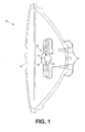
- FIG. 1 is an elevation view of an exemplary high intensity discharge lamp.
- FIG. 2 is a schematic illustration of an electronic ballast and control system for an HID strobe light.
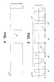
- FIG. 3 is a graphical representation of the polarity of electrical power during an operating interval of the HID strobe light.
- FIG. 4 is a graphic representation of input power during the operating interval illustrated in FIG. 3 .
- an exemplary high intensity discharge (HID) lamp 20 comprises, generally, a discharge tube 22, also known as an arc tube or burner, which is commonly mounted in an outer envelope 24.
- a discharge tube 22 typically comprises a quartz (fused silica) or ceramic tube containing a metal and an inert gas, such as Xenon or nitrogen.
- the discharge tube of a metal halide lamp commonly includes mercury which is liquid at room temperature and which vaporizes during operation of the lamp.
- a metal halide lamp typically includes a rare earth metal such as thulium or holmium which controls the spectrum of the light emitted by the lamp and a halogen, typically an iodide or a bromide, which combines with the rare earth metal to increase the density of the rare earth atoms in the discharge arc.
- Metal halide lamps are commonly filled with argon which has good ignition properties and which is inert and will not combine with the other materials in the discharge tube.
- a pair of tungsten electrodes 26,28 protrude into the interior of the discharge tube. The ends of the electrodes are spaced apart creating an arc gap 30 (indicated by a bracket).
- the discharge tube assembly may be, but often is not, enclosed in an outer enclosure 32 that may include mirrored reflector portions to focus the light output of the lamp.
- Electrical connectors 34 often comprising cables, enable detachable connection of the lamp to a ballast circuit which supplies power to the electrodes.
- Light is produced by an HID lamp when an electric current arcs between the closely spaced electrodes 26, 28 in the discharge tube. Free electrons in the arc collide with atoms of the vaporized metal in the discharge tube exciting the electrons of the metal atoms to a higher energy state. When the excited electrons return to their original, lower energy level, electromagnetic radiation is emitted having a wavelength that is determined by the energy level of the energized electrons and the constituency of the vapor in the discharge tube.
- An HID lamp is typically operated with an alternating current having a frequency in the range of 150 - 400 Hertz (Hz) and an operating voltage in the range of 45 - 225v. depending on the type of lamp.
- the alternating polarity of the current equalizes the temperatures of the electrodes and reduces electrode material loss.
- the relatively low frequency of the alternating current avoids acoustic resonance in the vapor which can cause the lamp to flicker, extinguish or even self destruct.
- ballast circuit power for the HID lamp 62 of the HID strobe light 50 is provided by a ballast circuit. While the ballast circuit may comprise a choke connected to an alternating current (ac) source, the ballast circuit 52 of the HID strobe light 50 comprises, generally, a constant power electronic ballast 54, an igniter 56, a bridge rectifier and a bridge controller 58.
- the ballast circuit converts a direct current (dc) input 60 to an alternating current of the correct frequency and voltage for operating the particular HID lamp.
- the dc input to the electronic ballast can be supplied by a battery or other dc source or may be supplied by a rectifier connected to an ac source.
- the electronic ballast steps up the dc input voltage to the lamp's operating voltage, typically 45 - 225v. and controls the magnitude of current flowing to the lamp.
- HID lamps typically exhibit a negative resistance characteristic.
- the lamp acts like an open circuit because the gas in the discharge tube is an effective electrical insulator, but as the material in the discharge tube is heated, the resistance drops significantly, first as the gas is ionized and then as the discharge arc is established.
- the electronic ballast 54 includes a current limiter that limits the flow of current to the lamp as the resistance changes.
- the constant power electronic ballast 54 is controllable to supply differing magnitudes of power to the lamp to enable different levels of illumination. Within the differing magnitudes of power, constant power is supplied to the lamp to accommodate variations in operating voltage due to lamp temperature, manufacturing tolerances, changes in lamp characteristics as the lamp ages and variations in the input voltage.
- the output of the electronic ballast 54 is direct current at the proper operating voltage for the lamp 62.
- the bridge rectifier converts the direct current at the output of the electronic ballast to the alternating current required for steady state operation of the lamp.
- the bridge rectifier comprises four transistors, commonly known as the upper left transistor 64, the upper right transistor 66, the lower left transistor 68 and the lower right transistor 70.
- the power at the lamp's terminals has a first polarity.
- the left terminal of the lamp is connected to the positive output terminal of the electronic ballast and the right hand terminal of the lamp is connected to the negative terminal of the ballast when the upper left and lower right transistors are conducting.
- the bridge controller 58 alternately triggers conduction by the diagonal pairs of the transistors in the bridge to provide a low frequency, square wave, alternating current for operating the lamp.
- a high voltage pulse commonly in the range of 2-20 kilovolts (kV)
- kV kilovolts
- An exemplary igniter comprises a pulse generator to generate a series of high voltage pulses usually lasting 0.5 - 2 seconds and a superimposing transformer that superimposes the high voltage pulses on the alternating current at the lamp's terminals.
- the high voltage pulses ionize the gas in the discharge tube, enabling the ionized gas to conduct a fairly high current between the electrodes of the lamp and producing a glow discharge.
- an HID lamp may require between 10 seconds and 15 minutes to reach full output from a cold start.
- metal halide lamps reach approximately 80% of full output within 3 minutes after ignition.
- HID lamps are sometimes operated at up to 110% of rated power and can be dimmed by reducing the power supplied to the lamp.
- operating an HID lamp at less approximately 60% of rated power can cause the arc to become unstable when the polarity reverses producing undesirable electromagnetic interference and, if there is insufficient energy flowing to the lamp to maintain an electrode temperature greater than the thermal electron emission temperature, the arc may extinguish. If the arc extinguishes, it may be necessary to allow the electrodes cool before restriking the lamp. Restriking a hot lamp commonly requires twice as much time as is required to start the lamp from a cold start.
- Some HID lamps are designed for "hot restrike" enabling the lamp to be reignited before the electrodes cool.
- a hot restrike typically requires an ignition pulse having approximately 10 times the voltage of the ignition pulse needed for a cold start and hot restriking can adversely effect the life of the lamp.
- the HID lamp 62 of the strobe light system 50 is typically excited with a 45-225v. alternating current that reverses polarity at a frequency between 150 Hz and 400 Hz. While FIG. 3 , illustrates the lamp as operating at full rated power and producing full light output during steady state operation, HID lamps are sometimes operated with up to 110% of full power or they may be dimmed by reducing power to the lamp. However, the power typically cannot be reduced to less than about 60% of rated power without risking arc instability and extinguishment.
- the lamp is dimmed when a dimming signal is applied at a dimming terminal 72 which is connected to appropriate control inputs 74, 76 of the electronic ballast 64 and the bridge controller 58, respectively.
- the presence of the signal at the dimming terminal causes the output of the electronic ballast to be reduced to less than 50% of rated and typically approximately 30% of rated power 120, as illustrated in FIG. 4 , and causes the bridge controller 58 to cease reversing the polarity at the lamp's terminals by maintaining the gate signals at a diagonal pair of transistors 64, 70 or 66, 68.
- the temperature of one of the electrodes can be maintained above the thermal electron emission temperature avoiding unstable lamp operation and the lamp's output will be reduced to the level of the glow discharge, a small fraction of the full light output of the lamp.
- the dimming signal is removed from the dimming terminal 72 signaling the ballast to resume supplying full power at its output while signaling the bridge controller to initiate a run up operation comprising a plurality of periodic reversals of the polarity of the power at the lamp's terminals.
- the bridge controller reverses the polarity of the power to the lamp and then repeatedly reverses the polarity at decreasing intervals for a run up interval 106. The period of each subsequent reversal during the run-up interval is shorter than the previous period.
- the polarity of the input power might be maintained for a time 108 approximately equal to three steady state power reversal intervals 116, followed by a polarity reversal lasting a period 110 equal to approximately two steady state polarity reversal periods and a third reversal interval 112 lasting approximately 1.5 steady state polarity reversal periods before the lamp resumes steady state operation 108 with periodically alternating polarity at the steady state periodicity (approximately 2 milliseconds - 7 milliseconds).
- the output of the HID lamp can be substantially reduced for an extended period of time and quickly returned to steady state operation at full output in anticipation of the next cycle of dimming.
- the HID strobe light provides the efficiency and spectral advantages of discharge lighting in a strobe light and enables the output of a high intensity discharge lamp to be substantially reduced and rapidly returned to full output without restriking the lamp.
Landscapes
- Circuit Arrangements For Discharge Lamps (AREA)
Applications Claiming Priority (2)
| Application Number | Priority Date | Filing Date | Title |
|---|---|---|---|
| US12430508P | 2008-04-15 | 2008-04-15 | |
| US12/157,374 US7919933B2 (en) | 2008-04-15 | 2008-06-09 | High intensity discharge strobe light |
Publications (2)
| Publication Number | Publication Date |
|---|---|
| EP2111084A1 true EP2111084A1 (de) | 2009-10-21 |
| EP2111084B1 EP2111084B1 (de) | 2012-01-18 |
Family
ID=40933970
Family Applications (1)
| Application Number | Title | Priority Date | Filing Date |
|---|---|---|---|
| EP09155835A Active EP2111084B1 (de) | 2008-04-15 | 2009-03-23 | Stroboskopische Hochdruckendladungslampe |
Country Status (4)
| Country | Link |
|---|---|
| US (1) | US7919933B2 (de) |
| EP (1) | EP2111084B1 (de) |
| AT (1) | ATE542397T1 (de) |
| ES (1) | ES2384344T3 (de) |
Families Citing this family (4)
| Publication number | Priority date | Publication date | Assignee | Title |
|---|---|---|---|---|
| JP4697326B2 (ja) * | 2009-04-01 | 2011-06-08 | ウシオ電機株式会社 | 高圧放電ランプ点灯装置 |
| JP5446721B2 (ja) * | 2009-10-26 | 2014-03-19 | パナソニック株式会社 | 放電ランプ点灯装置および投射型映像表示装置 |
| JP2015220058A (ja) * | 2014-05-16 | 2015-12-07 | ウシオ電機株式会社 | 放電ランプ点灯装置 |
| JP6307364B2 (ja) * | 2014-06-23 | 2018-04-04 | スタンレー電気株式会社 | ストロボ装置 |
Citations (2)
| Publication number | Priority date | Publication date | Assignee | Title |
|---|---|---|---|---|
| US5434479A (en) * | 1992-09-22 | 1995-07-18 | Matsushita Electric Works, Ltd. | Full-bridge inverter for discharge lamp lighting device with varied transistor zero voltage period |
| US20040183472A1 (en) * | 2001-05-25 | 2004-09-23 | Takeshi Kamoi | Electronic ballast for a high intensity discharge lamp |
Family Cites Families (6)
| Publication number | Priority date | Publication date | Assignee | Title |
|---|---|---|---|---|
| US3836797A (en) * | 1973-10-29 | 1974-09-17 | Collins Radio Co | Automatic intensity control for electronic displays |
| US5932976A (en) * | 1997-01-14 | 1999-08-03 | Matsushita Electric Works R&D Laboratory, Inc. | Discharge lamp driving |
| US6114814A (en) * | 1998-12-11 | 2000-09-05 | Monolithic Power Systems, Inc. | Apparatus for controlling a discharge lamp in a backlighted display |
| US6501231B1 (en) * | 2001-07-09 | 2002-12-31 | Amglo Kemlite Laboratories, Inc. | Metal halide lightbulb strobe system |
| US7420333B1 (en) * | 2004-01-29 | 2008-09-02 | Marvell International Ltd. | Mixed mode control for dimmable fluorescent lamp |
| US7030573B2 (en) * | 2004-04-20 | 2006-04-18 | Luminescent Systems, Inc. | High intensity discharge strobe lamp assembly and method for producing attenuated-EMI strobe illumination |
-
2008
- 2008-06-09 US US12/157,374 patent/US7919933B2/en active Active
-
2009
- 2009-03-23 EP EP09155835A patent/EP2111084B1/de active Active
- 2009-03-23 AT AT09155835T patent/ATE542397T1/de active
- 2009-03-23 ES ES09155835T patent/ES2384344T3/es active Active
Patent Citations (2)
| Publication number | Priority date | Publication date | Assignee | Title |
|---|---|---|---|---|
| US5434479A (en) * | 1992-09-22 | 1995-07-18 | Matsushita Electric Works, Ltd. | Full-bridge inverter for discharge lamp lighting device with varied transistor zero voltage period |
| US20040183472A1 (en) * | 2001-05-25 | 2004-09-23 | Takeshi Kamoi | Electronic ballast for a high intensity discharge lamp |
Also Published As
| Publication number | Publication date |
|---|---|
| US7919933B2 (en) | 2011-04-05 |
| ES2384344T3 (es) | 2012-07-04 |
| EP2111084B1 (de) | 2012-01-18 |
| ATE542397T1 (de) | 2012-02-15 |
| US20090256488A1 (en) | 2009-10-15 |
Similar Documents
| Publication | Publication Date | Title |
|---|---|---|
| US4763044A (en) | Start, hot restart and operating lamp circuit | |
| US7812544B2 (en) | Fluorescent light control | |
| US6172468B1 (en) | Method and apparatus for igniting a gas discharge lamp | |
| JP4052039B2 (ja) | 高圧放電ランプ点灯装置 | |
| KR100281373B1 (ko) | 고강도 방전 램프용 전자 밸러스트 | |
| US7919933B2 (en) | High intensity discharge strobe light | |
| JP4981424B2 (ja) | 高輝度放電ランプの瞬時高温再始動用の方法及び回路 | |
| US20110025233A1 (en) | Method and Apparatus For Reduction of Excess Current During Initial Firing of Arc Lamp Circuits | |
| US7982411B2 (en) | Ignition and operation of electronic high intensity discharge lamps | |
| US4963796A (en) | High-pressure sodium vapor lamp | |
| US20050231132A1 (en) | High intensity discharge strobe lamp assembly and method for producing attenuated-EMI strobe illumination | |
| US7045972B2 (en) | Lighting method of ultra-high pressure mercury lamp | |
| US20070262734A1 (en) | Filament Cutout Circuit | |
| CN104663001A (zh) | 改进灯驱动模块 | |
| KR20060047430A (ko) | 고압 방전 램프를 작동하는 방법 | |
| US8917036B1 (en) | Method and apparatus for dimming high intensity discharge lamps | |
| US7615941B2 (en) | Apparatus and method for maximizing the longevity of arc tube bulbs during pulsing operation | |
| JPS5926112B2 (ja) | 高圧放電灯 | |
| JP2001273984A (ja) | 高圧放電ランプの点灯方法及び点灯装置 | |
| KR100278071B1 (ko) | 가스방전등의 점등회로 | |
| JPS6396862A (ja) | ガス入り放電灯および放電灯装置 | |
| JPH08180985A (ja) | 放電灯点灯装置 | |
| JPH08321391A (ja) | 放電灯点灯装置 | |
| S'heeren | Eternal triangle: the interaction of light source, electrical control gear, and optics | |
| WO1998024277A1 (en) | Method and starter circuits for igniting and operating discharge lamps |
Legal Events
| Date | Code | Title | Description |
|---|---|---|---|
| PUAI | Public reference made under article 153(3) epc to a published international application that has entered the european phase |
Free format text: ORIGINAL CODE: 0009012 |
|
| AK | Designated contracting states |
Kind code of ref document: A1 Designated state(s): AT BE BG CH CY CZ DE DK EE ES FI FR GB GR HR HU IE IS IT LI LT LU LV MC MK MT NL NO PL PT RO SE SI SK TR |
|
| AX | Request for extension of the european patent |
Extension state: AL BA RS |
|
| 17P | Request for examination filed |
Effective date: 20100420 |
|
| 17Q | First examination report despatched |
Effective date: 20100601 |
|
| AKX | Designation fees paid |
Designated state(s): AT BE BG CH CY CZ DE DK EE ES FI FR GB GR HR HU IE IS IT LI LT LU LV MC MK MT NL NO PL PT RO SE SI SK TR |
|
| GRAP | Despatch of communication of intention to grant a patent |
Free format text: ORIGINAL CODE: EPIDOSNIGR1 |
|
| GRAS | Grant fee paid |
Free format text: ORIGINAL CODE: EPIDOSNIGR3 |
|
| RAP1 | Party data changed (applicant data changed or rights of an application transferred) |
Owner name: AUERSWALD SYSTEMS GMBH Owner name: PRECISE FLIGHT, INC. |
|
| GRAA | (expected) grant |
Free format text: ORIGINAL CODE: 0009210 |
|
| AK | Designated contracting states |
Kind code of ref document: B1 Designated state(s): AT BE BG CH CY CZ DE DK EE ES FI FR GB GR HR HU IE IS IT LI LT LU LV MC MK MT NL NO PL PT RO SE SI SK TR |
|
| REG | Reference to a national code |
Ref country code: GB Ref legal event code: FG4D |
|
| REG | Reference to a national code |
Ref country code: CH Ref legal event code: EP |
|
| REG | Reference to a national code |
Ref country code: AT Ref legal event code: REF Ref document number: 542397 Country of ref document: AT Kind code of ref document: T Effective date: 20120215 Ref country code: IE Ref legal event code: FG4D |
|
| REG | Reference to a national code |
Ref country code: DE Ref legal event code: R096 Ref document number: 602009004680 Country of ref document: DE Effective date: 20120322 |
|
| REG | Reference to a national code |
Ref country code: NL Ref legal event code: T3 |
|
| LTIE | Lt: invalidation of european patent or patent extension |
Effective date: 20120118 |
|
| REG | Reference to a national code |
Ref country code: ES Ref legal event code: FG2A Ref document number: 2384344 Country of ref document: ES Kind code of ref document: T3 Effective date: 20120704 |
|
| REG | Reference to a national code |
Ref country code: CH Ref legal event code: NV Representative=s name: RENTSCH PARTNER AG |
|
| PG25 | Lapsed in a contracting state [announced via postgrant information from national office to epo] |
Ref country code: HR Free format text: LAPSE BECAUSE OF FAILURE TO SUBMIT A TRANSLATION OF THE DESCRIPTION OR TO PAY THE FEE WITHIN THE PRESCRIBED TIME-LIMIT Effective date: 20120118 Ref country code: IS Free format text: LAPSE BECAUSE OF FAILURE TO SUBMIT A TRANSLATION OF THE DESCRIPTION OR TO PAY THE FEE WITHIN THE PRESCRIBED TIME-LIMIT Effective date: 20120518 Ref country code: NO Free format text: LAPSE BECAUSE OF FAILURE TO SUBMIT A TRANSLATION OF THE DESCRIPTION OR TO PAY THE FEE WITHIN THE PRESCRIBED TIME-LIMIT Effective date: 20120418 Ref country code: LT Free format text: LAPSE BECAUSE OF FAILURE TO SUBMIT A TRANSLATION OF THE DESCRIPTION OR TO PAY THE FEE WITHIN THE PRESCRIBED TIME-LIMIT Effective date: 20120118 Ref country code: BG Free format text: LAPSE BECAUSE OF FAILURE TO SUBMIT A TRANSLATION OF THE DESCRIPTION OR TO PAY THE FEE WITHIN THE PRESCRIBED TIME-LIMIT Effective date: 20120418 |
|
| PG25 | Lapsed in a contracting state [announced via postgrant information from national office to epo] |
Ref country code: LV Free format text: LAPSE BECAUSE OF FAILURE TO SUBMIT A TRANSLATION OF THE DESCRIPTION OR TO PAY THE FEE WITHIN THE PRESCRIBED TIME-LIMIT Effective date: 20120118 Ref country code: PT Free format text: LAPSE BECAUSE OF FAILURE TO SUBMIT A TRANSLATION OF THE DESCRIPTION OR TO PAY THE FEE WITHIN THE PRESCRIBED TIME-LIMIT Effective date: 20120518 Ref country code: PL Free format text: LAPSE BECAUSE OF FAILURE TO SUBMIT A TRANSLATION OF THE DESCRIPTION OR TO PAY THE FEE WITHIN THE PRESCRIBED TIME-LIMIT Effective date: 20120118 Ref country code: FI Free format text: LAPSE BECAUSE OF FAILURE TO SUBMIT A TRANSLATION OF THE DESCRIPTION OR TO PAY THE FEE WITHIN THE PRESCRIBED TIME-LIMIT Effective date: 20120118 Ref country code: GR Free format text: LAPSE BECAUSE OF FAILURE TO SUBMIT A TRANSLATION OF THE DESCRIPTION OR TO PAY THE FEE WITHIN THE PRESCRIBED TIME-LIMIT Effective date: 20120419 |
|
| REG | Reference to a national code |
Ref country code: AT Ref legal event code: MK05 Ref document number: 542397 Country of ref document: AT Kind code of ref document: T Effective date: 20120118 |
|
| PG25 | Lapsed in a contracting state [announced via postgrant information from national office to epo] |
Ref country code: CY Free format text: LAPSE BECAUSE OF FAILURE TO SUBMIT A TRANSLATION OF THE DESCRIPTION OR TO PAY THE FEE WITHIN THE PRESCRIBED TIME-LIMIT Effective date: 20120118 |
|
| PG25 | Lapsed in a contracting state [announced via postgrant information from national office to epo] |
Ref country code: DK Free format text: LAPSE BECAUSE OF FAILURE TO SUBMIT A TRANSLATION OF THE DESCRIPTION OR TO PAY THE FEE WITHIN THE PRESCRIBED TIME-LIMIT Effective date: 20120118 Ref country code: RO Free format text: LAPSE BECAUSE OF FAILURE TO SUBMIT A TRANSLATION OF THE DESCRIPTION OR TO PAY THE FEE WITHIN THE PRESCRIBED TIME-LIMIT Effective date: 20120118 Ref country code: SI Free format text: LAPSE BECAUSE OF FAILURE TO SUBMIT A TRANSLATION OF THE DESCRIPTION OR TO PAY THE FEE WITHIN THE PRESCRIBED TIME-LIMIT Effective date: 20120118 Ref country code: SE Free format text: LAPSE BECAUSE OF FAILURE TO SUBMIT A TRANSLATION OF THE DESCRIPTION OR TO PAY THE FEE WITHIN THE PRESCRIBED TIME-LIMIT Effective date: 20120118 Ref country code: MC Free format text: LAPSE BECAUSE OF NON-PAYMENT OF DUE FEES Effective date: 20120331 Ref country code: EE Free format text: LAPSE BECAUSE OF FAILURE TO SUBMIT A TRANSLATION OF THE DESCRIPTION OR TO PAY THE FEE WITHIN THE PRESCRIBED TIME-LIMIT Effective date: 20120118 Ref country code: CZ Free format text: LAPSE BECAUSE OF FAILURE TO SUBMIT A TRANSLATION OF THE DESCRIPTION OR TO PAY THE FEE WITHIN THE PRESCRIBED TIME-LIMIT Effective date: 20120118 |
|
| PLBE | No opposition filed within time limit |
Free format text: ORIGINAL CODE: 0009261 |
|
| STAA | Information on the status of an ep patent application or granted ep patent |
Free format text: STATUS: NO OPPOSITION FILED WITHIN TIME LIMIT |
|
| PG25 | Lapsed in a contracting state [announced via postgrant information from national office to epo] |
Ref country code: SK Free format text: LAPSE BECAUSE OF FAILURE TO SUBMIT A TRANSLATION OF THE DESCRIPTION OR TO PAY THE FEE WITHIN THE PRESCRIBED TIME-LIMIT Effective date: 20120118 |
|
| 26N | No opposition filed |
Effective date: 20121019 |
|
| REG | Reference to a national code |
Ref country code: IE Ref legal event code: MM4A |
|
| PG25 | Lapsed in a contracting state [announced via postgrant information from national office to epo] |
Ref country code: AT Free format text: LAPSE BECAUSE OF FAILURE TO SUBMIT A TRANSLATION OF THE DESCRIPTION OR TO PAY THE FEE WITHIN THE PRESCRIBED TIME-LIMIT Effective date: 20120118 Ref country code: IE Free format text: LAPSE BECAUSE OF NON-PAYMENT OF DUE FEES Effective date: 20120323 |
|
| REG | Reference to a national code |
Ref country code: DE Ref legal event code: R097 Ref document number: 602009004680 Country of ref document: DE Effective date: 20121019 |
|
| PG25 | Lapsed in a contracting state [announced via postgrant information from national office to epo] |
Ref country code: MK Free format text: LAPSE BECAUSE OF FAILURE TO SUBMIT A TRANSLATION OF THE DESCRIPTION OR TO PAY THE FEE WITHIN THE PRESCRIBED TIME-LIMIT Effective date: 20120118 |
|
| PG25 | Lapsed in a contracting state [announced via postgrant information from national office to epo] |
Ref country code: MT Free format text: LAPSE BECAUSE OF FAILURE TO SUBMIT A TRANSLATION OF THE DESCRIPTION OR TO PAY THE FEE WITHIN THE PRESCRIBED TIME-LIMIT Effective date: 20120118 |
|
| PG25 | Lapsed in a contracting state [announced via postgrant information from national office to epo] |
Ref country code: TR Free format text: LAPSE BECAUSE OF FAILURE TO SUBMIT A TRANSLATION OF THE DESCRIPTION OR TO PAY THE FEE WITHIN THE PRESCRIBED TIME-LIMIT Effective date: 20120118 |
|
| PG25 | Lapsed in a contracting state [announced via postgrant information from national office to epo] |
Ref country code: LU Free format text: LAPSE BECAUSE OF NON-PAYMENT OF DUE FEES Effective date: 20120323 |
|
| PG25 | Lapsed in a contracting state [announced via postgrant information from national office to epo] |
Ref country code: HU Free format text: LAPSE BECAUSE OF FAILURE TO SUBMIT A TRANSLATION OF THE DESCRIPTION OR TO PAY THE FEE WITHIN THE PRESCRIBED TIME-LIMIT Effective date: 20090323 |
|
| REG | Reference to a national code |
Ref country code: FR Ref legal event code: PLFP Year of fee payment: 8 |
|
| REG | Reference to a national code |
Ref country code: FR Ref legal event code: PLFP Year of fee payment: 9 |
|
| REG | Reference to a national code |
Ref country code: CH Ref legal event code: PCAR Free format text: NEW ADDRESS: BELLERIVESTRASSE 203 POSTFACH, 8034 ZUERICH (CH) |
|
| REG | Reference to a national code |
Ref country code: FR Ref legal event code: PLFP Year of fee payment: 10 |
|
| PGFP | Annual fee paid to national office [announced via postgrant information from national office to epo] |
Ref country code: FR Payment date: 20230327 Year of fee payment: 15 |
|
| PGFP | Annual fee paid to national office [announced via postgrant information from national office to epo] |
Ref country code: IT Payment date: 20230321 Year of fee payment: 15 Ref country code: GB Payment date: 20230327 Year of fee payment: 15 Ref country code: DE Payment date: 20230329 Year of fee payment: 15 Ref country code: BE Payment date: 20230327 Year of fee payment: 15 |
|
| PGFP | Annual fee paid to national office [announced via postgrant information from national office to epo] |
Ref country code: NL Payment date: 20230326 Year of fee payment: 15 |
|
| PGFP | Annual fee paid to national office [announced via postgrant information from national office to epo] |
Ref country code: ES Payment date: 20230403 Year of fee payment: 15 Ref country code: CH Payment date: 20230402 Year of fee payment: 15 |
|
| REG | Reference to a national code |
Ref country code: DE Ref legal event code: R119 Ref document number: 602009004680 Country of ref document: DE |
|
| REG | Reference to a national code |
Ref country code: CH Ref legal event code: PL |
|
| REG | Reference to a national code |
Ref country code: NL Ref legal event code: MM Effective date: 20240401 |
|
| GBPC | Gb: european patent ceased through non-payment of renewal fee |
Effective date: 20240323 |
|
| PG25 | Lapsed in a contracting state [announced via postgrant information from national office to epo] |
Ref country code: NL Free format text: LAPSE BECAUSE OF NON-PAYMENT OF DUE FEES Effective date: 20240401 |
|
| REG | Reference to a national code |
Ref country code: BE Ref legal event code: MM Effective date: 20240331 |
|
| PG25 | Lapsed in a contracting state [announced via postgrant information from national office to epo] |
Ref country code: NL Free format text: LAPSE BECAUSE OF NON-PAYMENT OF DUE FEES Effective date: 20240401 |
|
| PG25 | Lapsed in a contracting state [announced via postgrant information from national office to epo] |
Ref country code: DE Free format text: LAPSE BECAUSE OF NON-PAYMENT OF DUE FEES Effective date: 20241001 |
|
| PG25 | Lapsed in a contracting state [announced via postgrant information from national office to epo] |
Ref country code: BE Free format text: LAPSE BECAUSE OF NON-PAYMENT OF DUE FEES Effective date: 20240331 |
|
| PG25 | Lapsed in a contracting state [announced via postgrant information from national office to epo] |
Ref country code: GB Free format text: LAPSE BECAUSE OF NON-PAYMENT OF DUE FEES Effective date: 20240323 |
|
| PG25 | Lapsed in a contracting state [announced via postgrant information from national office to epo] |
Ref country code: FR Free format text: LAPSE BECAUSE OF NON-PAYMENT OF DUE FEES Effective date: 20240331 |
|
| PG25 | Lapsed in a contracting state [announced via postgrant information from national office to epo] |
Ref country code: GB Free format text: LAPSE BECAUSE OF NON-PAYMENT OF DUE FEES Effective date: 20240323 Ref country code: FR Free format text: LAPSE BECAUSE OF NON-PAYMENT OF DUE FEES Effective date: 20240331 Ref country code: DE Free format text: LAPSE BECAUSE OF NON-PAYMENT OF DUE FEES Effective date: 20241001 Ref country code: BE Free format text: LAPSE BECAUSE OF NON-PAYMENT OF DUE FEES Effective date: 20240331 Ref country code: CH Free format text: LAPSE BECAUSE OF NON-PAYMENT OF DUE FEES Effective date: 20240331 |
|
| PG25 | Lapsed in a contracting state [announced via postgrant information from national office to epo] |
Ref country code: IT Free format text: LAPSE BECAUSE OF NON-PAYMENT OF DUE FEES Effective date: 20240323 |
|
| PG25 | Lapsed in a contracting state [announced via postgrant information from national office to epo] |
Ref country code: ES Free format text: LAPSE BECAUSE OF NON-PAYMENT OF DUE FEES Effective date: 20240324 |