EP2111092A2 - Tête à implanter, automate d'implantation, procédé destiné à aller chercher des composants et procédé destiné à implanter des substrats - Google Patents
Tête à implanter, automate d'implantation, procédé destiné à aller chercher des composants et procédé destiné à implanter des substrats Download PDFInfo
- Publication number
- EP2111092A2 EP2111092A2 EP09154944A EP09154944A EP2111092A2 EP 2111092 A2 EP2111092 A2 EP 2111092A2 EP 09154944 A EP09154944 A EP 09154944A EP 09154944 A EP09154944 A EP 09154944A EP 2111092 A2 EP2111092 A2 EP 2111092A2
- Authority
- EP
- European Patent Office
- Prior art keywords
- pipette
- placement
- substrate
- pipettes
- placement head
- Prior art date
- Legal status (The legal status is an assumption and is not a legal conclusion. Google has not performed a legal analysis and makes no representation as to the accuracy of the status listed.)
- Granted
Links
Images


Classifications
-
- H—ELECTRICITY
- H05—ELECTRIC TECHNIQUES NOT OTHERWISE PROVIDED FOR
- H05K—PRINTED CIRCUITS; CASINGS OR CONSTRUCTIONAL DETAILS OF ELECTRIC APPARATUS; MANUFACTURE OF ASSEMBLAGES OF ELECTRICAL COMPONENTS
- H05K13/00—Apparatus or processes specially adapted for manufacturing or adjusting assemblages of electric components
- H05K13/04—Mounting of components, e.g. of leadless components
- H05K13/0404—Pick-and-place heads or apparatus, e.g. with jaws
- H05K13/0408—Incorporating a pick-up tool
- H05K13/041—Incorporating a pick-up tool having multiple pick-up tools
-
- H—ELECTRICITY
- H05—ELECTRIC TECHNIQUES NOT OTHERWISE PROVIDED FOR
- H05K—PRINTED CIRCUITS; CASINGS OR CONSTRUCTIONAL DETAILS OF ELECTRIC APPARATUS; MANUFACTURE OF ASSEMBLAGES OF ELECTRICAL COMPONENTS
- H05K13/00—Apparatus or processes specially adapted for manufacturing or adjusting assemblages of electric components
- H05K13/04—Mounting of components, e.g. of leadless components
- H05K13/0404—Pick-and-place heads or apparatus, e.g. with jaws
- H05K13/0413—Pick-and-place heads or apparatus, e.g. with jaws with orientation of the component while holding it; Drive mechanisms for gripping tools, e.g. lifting, lowering or turning of gripping tools
Definitions
- the invention relates to the field of automatic placement of substrates by means of placement machines, which have a placement head for temporarily holding components, so that when a corresponding movement of the placement head, the components can be picked up, transported and placed on a component carrier.
- the present invention relates in particular to a placement head for equipping substrates with components. Furthermore, the present invention relates to a placement, a method for picking up components and a method for loading substrates.
- substrates for example printed circuit boards
- placement machines are equipped with components of various types with the aid of so-called placement machines.
- the components are provided by means arranged on the placement feeders at defined collection positions.
- a placement head of the placement machine which can be moved by a positioning system picks up the components at the pick-up positions and transfers them to a placement area of the placement machine, where they are positioned on provided substrates.
- Substrates to be loaded are fed to the placement area via a transport device, and finished substrates are transported out of the placement area via this transport device.
- a placement machine is for example from the patent DE 10336609 B3 known.
- a placement head with a plurality of grippers which has a longitudinal or a transverse guide for a displaceable therein longitudinal or transverse slide, wherein one of the gripper on the longitudinal slide and the other gripper on the cross slide is fixed so that they are displaceable parallel to a substrate plane.
- the placement head according to the invention for equipping substrates with components for a placement machine has at least one first and one second pipette carrier, which are configured to receive pipettes, wherein at least the first pipette carrier has a plurality of pipettes for handling the components.
- the pipettes are arranged at their respective pipette carrier in a plane parallel to a plane of the substrate and displaceable relative to their respective pipette carrier along their respective axis in a z-direction perpendicular to the plane of the substrate and rotatable about that respective axis.
- At least the first pipette carrier is rotatable about an axis of rotation, which is oriented perpendicular to the plane of the substrate.
- placement of the placement of a positioning of the placement machine is arranged linearly movable, so that a fixed relative to the placement substrate at the same time held relative to the placement machine positioning at least stripwise equippable.
- strip-wise assembly is understood to mean that a strip of the substrate, ie a region having a width other than zero, can be equipped with the stationary substrate and fixed positioning system with the aid of the placement head according to the invention.
- the positioning system is either movable or designed as a fixed linear guide for the placement. Prerequisite for the strip-wise loading is merely that the positioning system rests during the assembly of the stiff with multiple components. Strip-wise loading is then carried out exclusively by the linear movement of the placement head on the positioning system and by the adjustment of individual pipettes or pipette carrier transversely to the direction of travel of the placement.
- the "strip-wise assembly" can be defined such that a plurality of components can be positioned at their placement positions within a strip of the substrate to be loaded, wherein the placement positions may have a different distance to a vertical projection of the travel axis of the placement on the substrate.
- the width of the strip is limited by the maximum operating radius of the pipettes.
- the axis of rotation is arranged eccentrically relative to the respective pipette carrier, so that the respective pipette carrier is pivotable in a plane parallel to the plane of the substrate.
- a swivel axis for the pipette carrier provides an easy way to move the pipettes arranged on the pipette carrier in a plane parallel to the plane of the substrate, without having to use linear axes or guides.
- off-center is understood to mean that the pivot axis, which is oriented perpendicular to the plane of the substrate, is arranged in a sectional plane parallel to the plane of the substrate either in an edge region of the pipette carrier or completely outside the outline of the pipette carrier.
- the pivot axis is by no means arranged at the intersection of the symmetry axes of the pipette carrier.
- At least one of the pipette carriers is linearly movable relative to the other pipette carrier at least in one direction parallel to the plane of the substrate at the placement head.
- the additional degree of freedom realized by the linear movement of one of the two pipette carriers enables independent positioning of two pipettes which are arranged on different pipette carriers. It is thereby possible to position at least two components held by the pipettes in a plane parallel to the plane of the substrate in such a way that they can be deposited simultaneously on their placement positions on the substrate by means of a feed movement in the z direction. As a result, the time proportion for the loading of the substrate can be significantly reduced, which in turn significantly increases the placement performance of the placement machine.
- each pipette carrier has a z-drive for moving at least one of the pipettes along their respective axis in the z-direction, wherein the z-drive thereby at least one any pipette of the respective pipette carrier can be coupled.
- the z-drive With the aid of the z-drive, it is possible to lower and / or raise a single pipette in a targeted manner in the z-direction perpendicular to the plane of the substrate.
- the z-drive can be coupled with the respective pipette.
- the mass accelerated in the z-direction is significantly reduced, which leads to an improved vibration behavior and thus to a higher placement accuracy.
- the lower moving mass higher accelerations are possible, which has a positive effect on the placement.
- each pipette of a pipette carrier is assigned its own, separately controllable z-drive, which allows a movement of the respective pipette in the z-direction.
- each pipette has its own, individually controllable z-drive, the axes of the individual pipettes can already be pre-positioned in the z-direction during the movement of the placement head.
- each pipette of a pipette carrier is associated with its own, separately controllable rotary drive, which allows a rotational movement of the respective pipette about their respective axis.
- each pipette is assigned its own, individually controllable rotary drive, can already during the movement of the placement or during the pre-positioning of the pipette in the z direction, a correction of the angular position of the held component about the respective z-axis of the Pipette.
- the placement can be further increased.
- At least the first pipette carrier has a plurality of pipettes, which are arranged in a straight line, so that the pipette carrier is pivotable in a plane parallel to the plane of the substrate by means of the eccentrically arranged axis of rotation.
- the axis of rotation is arranged eccentrically relative to the pipette carrier.
- the "action radius" of the individual pipettes can be increased around the axis of rotation, which allows greater flexibility in the relative positioning of multiple pipettes of different pipette carriers.
- the placement machine according to the invention for equipping substrates with components has a positioning system, which is arranged on a chassis of the placement and designed to accommodate at least one placement head, and a first placement head according to one of claims 1 to 9.
- the placement of the positioning system is designed as a fixed portal, which is firmly connected to the chassis, so that the placement is exclusively linearly movable by means of the positioning.
- the positioning system is designed as a fixed portal or guide element can be selected as a cost-effective implementation possibility.
- the positioning system is no longer movable relative to a machine base of the placement. All positioning movements within a strip of the substrate to be loaded are carried out by a linear movement of the placement head on the fixed positioning system and by movements of the pipettes and / or pipette carriers on the placement head. For equipping another Strip of the substrate is this cross, preferably orthogonal, proceeded to the direction of travel of the placement on the positioning system.
- a plurality of components can be positioned simultaneously on the substrate.
- the use of the placement head according to the invention allows a positioning of several pipettes relative to one another in a plane parallel to the plane of the substrate. This allows simultaneous deposition of several components on the substrate. The placement of the placement can be significantly increased.
- At least one further placement head is movably arranged on the positioning system.
- Each of the placement heads is assigned its own drive unit, which allow independent movement of the placement heads on the positioning system.
- a placement head which is designed according to one of claims 1 to 9 for a placement machine having feed means by which the components are provided at pickup positions
- pipettes of multiple pipette carriers are pre-positioned such that a plurality of components simultaneously by a feed movement of the respective pipettes in a z-direction perpendicular to a Level of the substrate to be picked up from their respective pickup positions.
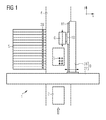
- FIG. 1 schematically shows the general structure of a placement machine 1 for equipping substrates 2 with components 3, which is suitable for receiving the placement head 6 according to the invention.
- the placement machine 1 has a cross member 27, which extends in a y-direction and fixed to a machine frame (not shown) is connected.
- a portal arm 28 is mounted, which extends in the x direction and is slidably mounted in the y direction on the cross member 27.
- Cross member 27 and portal arm 28 together form the positioning system 9, wherein an orthogonal reference frame is formed by the x-axis and the y-axis.
- a placement head 6 is mounted displaceably in the x direction, which can be moved defined by means of a drive unit 10 in the x direction along a arranged on the portal arm 28 guide member 11. Furthermore, a transport path 4 for transporting the substrates 2 in an assembly area of the placement machine 1 provided. Side of the transport path 4 are arranged in the vicinity of the placement area feeders 5, which provide the components 3 at their respective pick-up positions 26.
- the placement head 6 For loading a substrate 2, this is transported via the transport path 4 in the placement area.
- the electrical components 3 provided by the feed device 5 are picked up by the placement head 6 and transferred to the placement area, where they are positioned on the substrate 2 at their respective placement positions.
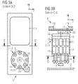
- FIGS. 2 to 4 show in each case only the first pipette support 7-1x concretely executed in all three embodiments, the second pipette support 7-2 is shown only schematically and can be configured arbitrarily. Since the first pipette carrier 7-1x in the FIGS. 2 to 4 is executed differently, the last digit of the respective reference refers to the respective figure. If the first pipette carrier is addressed in general, this is indicated by the placeholder x.
- the first pipette carrier 7-1x has a plurality of pipettes 8, which are arranged on the first pipette carrier 7-1x in an x / y plane.
- the x / y plane is parallel to a substrate plane, which is determined by the surface of the substrate 2 to be equipped, on which the components 3 are deposited.
- the individual pipettes 8 are displaceable along a z-direction perpendicular to the substrate plane and rotatable about their respective pipette axis 18, so that components 3 held by the pipettes can be positioned with regard to their angular position and can be deposited on the substrate 2.
- each pipette 8 is assigned its own z-drive 15 and its own rotary drive 14.
- first pipette carrier 7-1x also has an axis of rotation 12, which is likewise oriented in the z-direction perpendicular to the substrate plane.
- first pipette carrier 7-1x with the pipettes arranged thereon can be rotated or pivoted in a plane parallel to the plane of the substrate 2.
- FIGS. 2a and 2b show a first embodiment of the placement head 6, wherein FIG. 2a a sectional view taken along the line BB, and FIG. 2b show a sectional view along the line AA.
- the first pipette carrier 7-12 is designed to rotate horizontally and has a stator 16 and a rotor 13 on which the individual pipettes 8 are arranged. While the stator 16 is fixedly arranged on the placement head 6, the rotor 13 is rotatably mounted about an axis of rotation 12. Thus, the pipettes 8 can be moved in a plane parallel to the substrate plane.
- FIGS. 3a and 3b show a second embodiment of the placement head 6, wherein FIG. 3a a sectional view taken along the line DD, and FIG. 3b a sectional view along the line CC show.
- the first pipette carrier 7-13 is in turn designed to rotate horizontally and accordingly also has a stator 16 and a rotor 13 rotating about the stator, on which the pipettes 8 are arranged.
- the rotation axis 12 is arranged off-center, so that the first pipette carrier 7-13 pivots about this axis of rotation 12 by means of a pivoting arm 23 can be.
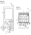
- FIGS. 4a and 4b show a third embodiment of the placement head 6, wherein FIG. 4a a sectional view taken along the line FF, and FIG. 4b show a sectional view along the line EE.
- the individual pipettes 8 of the first pipette carrier 7-14 are arranged in a straight line in a row.
- the first pipette carrier 7-14 itself is rotatable about the axis of rotation 12, so that the individual pipettes 8 can be moved in the x / y plane, parallel to the substrate plane.
- the first pipette carrier is 7-14 in FIG. 4a still shown in two other possible positions, resulting from a rotation about the axis of rotation 12, shown in dashed lines.
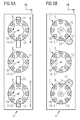
- FIGS. 5a to 5c show further embodiments of the placement head 6 according to the invention, which have more than two pipette carriers 7.
- FIG. 5a shows a placement head 6 with three horizontally rotating pipette carriers 7, which in terms of their construction from that of the FIGS. 2a and 2b correspond to known first pipette carrier 7-12. All three pipette carriers 7 have a rotatable about a rotation axis 12 rotor 13, on which the individual pipettes 8 are arranged. The individual pipettes 8 are displaceable along a z-direction perpendicular to the x / y-plane and rotatable about their respective pipette axis 18. For this purpose, each pipette 8 is assigned its own rotary drive 14 and its own z-drive 15.
- the middle pipette carrier 7 is arranged stationarily on the placement head 6, the two outer pipette carriers 7 are along one Linear guide 22 relative to the placement head 6 slidably.
- This additional degree of freedom enables independent positioning of two pipettes which are arranged on different pipette carriers. While the relative positioning of the two pipettes 8 in the y-direction is achieved by a rotational movement of the respective pipette carrier 7, the positioning in the x-direction is effected by a corresponding movement of the respective pipette carrier 7 along the respective linear guide 22.
- components 3, whose Placement positions are arranged on the substrate 2 immediately adjacent to each other, simultaneously or immediately successively deposited on the substrate 2, without the need for this, the entire placement head 6 must be moved in the meantime.
- FIG. 5b shows a further embodiment of the placement head 6 according to the invention also with three horizontally rotating pipette carriers 7. While the middle pipette carrier 7 is in turn fixedly mounted on the placement head 6, the two outer pipette carrier 7 correspond in terms of their construction from that of the FIGS. 3a and 3b known first pipette support 7-13. Both have an eccentrically arranged axis of rotation 12 about which the respective pipette carrier 7 can be pivoted. Since a relative movement of the individual pipette carriers 7 relative to one another can also be realized by the pivoting movement, there is no additional linear guide 22 for this embodiment, as in FIG FIG. 5a shown embodiment required.
- FIG. 5c shows a third embodiment of the placement head 6 according to the invention with also three pipette carriers 7, the pipettes 8 are each arranged in a straight line in a row.
- the three pipette carriers 7 are identical and correspond to that of the FIGS. 4a and 4b known first pipette support 7-14.
- the pipette carriers 7 are each arranged around their arranged in the edge region of the respective pipette carrier and oriented in the z direction Rotation axis 12 rotatable so that the individual pipettes 8 of the respective pipette carrier 7 in the x / y-plane, parallel to the substrate plane, can be moved.
- each of the pipette carriers 7 is shown in dashed lines in two further possible positions resulting from a rotation about the rotation axis 12 by 45 ° or 90 °. If, in addition, the pitch of the pipettes 8 arranged on the respective pipette carrier 7 corresponds to the pitch of the pick-up positions 26 of the feed devices 5 (see FIG FIG.
- FIGS. 6a and 6b each show a sectional view of the placement machine according to the invention (1) in a plan view, wherein the cutting plane below the positioning system 9 (see FIG. 1 ) was placed so that the placement heads 6 are not obscured by the positioning system 9.
- the positioning system 9 can be designed as a fixed portal, which is firmly connected to a chassis 17 of the placement machine 1, so that the two placement heads 6 are arranged movable only in the x-direction on the portal.
- the two placement heads 6 are thereby guided hanging on the positioning system 9.
- the placement machine 1 further has a transport path 4 for transporting substrates 2 in a y-direction. Furthermore, the placement machine 1 feeders 5, by means of which the components 3 at defined collection positions 26 are provided for pickup by a placement head 6.
- the two in the FIGS. 6a and 6b Placement machines 1 shown differ only in the embodiment of the assembled placement heads. 6
- FIG. 6a the placement machine 1 is equipped with two identical placement heads 6, as they are already out FIG. 5b are known.
- the two placement heads 6 are arranged in mirror image relative to one another on a common positioning system 9 (not shown) so as to be linearly displaceable in the x-direction.
- Both placement heads 6 each have three pipette carriers 7, of which in each case the two outer pivots are arranged on the placement head 6. This makes it possible to equip a significantly wider strip S of the substrate 2 in strips, ie exclusively by positioning movements of the placement head 6, without having to move the positioning system 9 or the substrate 2.
- Placement machine 1 shown is equipped with two different placement heads 6.
- One of the two placement heads 6 has three horizontally rotating pipette carrier 7 and is already from the description FIG. 5a known.
- the other placement head 6 has three pivotable pipette carriers 7, the pipettes 8 are each arranged in a straight line in a row, and is already out of the description to FIG. 5c known. Even with this configuration, it is possible to handle a plurality of components 3 at the same time or to equip a substrate 2 in strips.
- the pipettes 8 of a plurality of pipette carriers 7 are initially prepositioned such that their relative position to one another corresponds to the relative position of the corresponding placement positions on the substrate 2, whereby again only the degrees of freedom of the placement head 6 are utilized , The relative position of the positioning system 9 to the substrate 2 remains unchanged. Subsequently, a plurality of components are simultaneously deposited on their respective placement positions on the substrate 2 by a simultaneous feed movement of the prepositioned pipettes 8 in the z-direction.
- the positioning system 9 can be moved in the y-direction (if it is correspondingly movable) or-if the positioning system 9 is designed as a fixed portal-the substrate 2 is moved along the transport path 4 further transported by a strip width in the y direction.
Landscapes
- Engineering & Computer Science (AREA)
- Manufacturing & Machinery (AREA)
- Microelectronics & Electronic Packaging (AREA)
- Supply And Installment Of Electrical Components (AREA)
- Automatic Assembly (AREA)
- Container, Conveyance, Adherence, Positioning, Of Wafer (AREA)
Applications Claiming Priority (1)
| Application Number | Priority Date | Filing Date | Title |
|---|---|---|---|
| DE102008019100A DE102008019100B3 (de) | 2008-04-16 | 2008-04-16 | Bestückkopf, Bestückautomat, Verfahren zum Abholen von Bauelementen sowie Verfahren zum Bestücken von Substraten |
Publications (3)
| Publication Number | Publication Date |
|---|---|
| EP2111092A2 true EP2111092A2 (fr) | 2009-10-21 |
| EP2111092A3 EP2111092A3 (fr) | 2011-05-18 |
| EP2111092B1 EP2111092B1 (fr) | 2015-05-27 |
Family
ID=40671156
Family Applications (1)
| Application Number | Title | Priority Date | Filing Date |
|---|---|---|---|
| EP09154944.4A Ceased EP2111092B1 (fr) | 2008-04-16 | 2009-03-12 | Tête à implanter, automate d'implantation, procédé destiné à aller chercher des composants et procédé destiné à implanter des substrats |
Country Status (3)
| Country | Link |
|---|---|
| EP (1) | EP2111092B1 (fr) |
| CN (1) | CN101562966B (fr) |
| DE (1) | DE102008019100B3 (fr) |
Cited By (2)
| Publication number | Priority date | Publication date | Assignee | Title |
|---|---|---|---|---|
| EP2012576A3 (fr) * | 2007-07-06 | 2011-04-27 | ASM Assembly Systems GmbH & Co. KG | Automate d'implantation et procédé de manipulation de composants |
| EP3930437A1 (fr) * | 2020-06-22 | 2021-12-29 | ASM Assembly Systems GmbH & Co. KG | Tête de positionnement dotée de deux agencements de rotor avec des dispositifs de manipulation actionnables individuellement |
Families Citing this family (6)
| Publication number | Priority date | Publication date | Assignee | Title |
|---|---|---|---|---|
| SG10201807846WA (en) * | 2012-06-28 | 2018-10-30 | Universal Instruments Corp | Flexible assembly machine, system and method |
| DE102014103373B4 (de) * | 2014-03-12 | 2021-11-18 | Asm Assembly Systems Gmbh & Co. Kg | Bestückkopf mit zwei relativ zu einem Schaft beweglichen Gruppen von Pinolen, Bestückautomat und Verfahren zum Bestücken |
| KR102416621B1 (ko) | 2015-08-31 | 2022-07-05 | 삼성디스플레이 주식회사 | 발광 다이오드 트랜스퍼 |
| CN108706341B (zh) * | 2018-04-19 | 2023-12-08 | 杭州千龙实业有限公司 | 一种山核桃捞取装置 |
| EP3833174A1 (fr) * | 2019-12-06 | 2021-06-09 | Mycronic AB | Outil de montage pour une machine de montage de composants |
| US11389819B2 (en) * | 2020-06-02 | 2022-07-19 | Illinois Tool Works Inc. | Dispensing unit mass dampener |
Citations (2)
| Publication number | Priority date | Publication date | Assignee | Title |
|---|---|---|---|---|
| DE10336609B3 (de) | 2003-08-08 | 2005-02-17 | Siemens Ag | Vorrichtung zum Bestücken von flachen Substraten mit elektrischen Bauelementen |
| DE10236604B4 (de) | 2002-08-09 | 2006-07-06 | Siemens Ag | Bestückkopf mit mindestens zwei Greifern für elektrische Bauelemente |
Family Cites Families (6)
| Publication number | Priority date | Publication date | Assignee | Title |
|---|---|---|---|---|
| JP2620646B2 (ja) * | 1989-06-07 | 1997-06-18 | 三洋電機株式会社 | 電子部品自動装着装置 |
| JP2002511665A (ja) * | 1998-04-09 | 2002-04-16 | シーメンス アクチエンゲゼルシヤフト | コンポーネント担体にマウントするためのマウント装置 |
| KR100445530B1 (ko) * | 1999-05-10 | 2004-08-21 | 미래산업 주식회사 | 반도체장치 |
| JP2001135993A (ja) * | 1999-11-08 | 2001-05-18 | Matsushita Electric Ind Co Ltd | 部品実装装置および部品実装方法 |
| US7302755B2 (en) * | 2005-02-07 | 2007-12-04 | Samsung Techwin Co., Ltd. | Head assembly for a component mounter |
| JP4584740B2 (ja) * | 2005-02-28 | 2010-11-24 | パナソニック株式会社 | 部品実装方法及び部品実装装置 |
-
2008
- 2008-04-16 DE DE102008019100A patent/DE102008019100B3/de not_active Expired - Fee Related
-
2009
- 2009-03-12 EP EP09154944.4A patent/EP2111092B1/fr not_active Ceased
- 2009-04-16 CN CN200910134470.6A patent/CN101562966B/zh not_active Expired - Fee Related
Patent Citations (2)
| Publication number | Priority date | Publication date | Assignee | Title |
|---|---|---|---|---|
| DE10236604B4 (de) | 2002-08-09 | 2006-07-06 | Siemens Ag | Bestückkopf mit mindestens zwei Greifern für elektrische Bauelemente |
| DE10336609B3 (de) | 2003-08-08 | 2005-02-17 | Siemens Ag | Vorrichtung zum Bestücken von flachen Substraten mit elektrischen Bauelementen |
Cited By (5)
| Publication number | Priority date | Publication date | Assignee | Title |
|---|---|---|---|---|
| EP2012576A3 (fr) * | 2007-07-06 | 2011-04-27 | ASM Assembly Systems GmbH & Co. KG | Automate d'implantation et procédé de manipulation de composants |
| EP3930437A1 (fr) * | 2020-06-22 | 2021-12-29 | ASM Assembly Systems GmbH & Co. KG | Tête de positionnement dotée de deux agencements de rotor avec des dispositifs de manipulation actionnables individuellement |
| CN113905605A (zh) * | 2020-06-22 | 2022-01-07 | 先进装配系统有限责任两合公司 | 具有带可单独启动的操纵装置的两个转子组件的装配头 |
| CN113905605B (zh) * | 2020-06-22 | 2023-04-07 | 先进装配系统有限责任两合公司 | 具有带可单独启动的操纵装置的两个转子组件的装配头 |
| US12120824B2 (en) | 2020-06-22 | 2024-10-15 | ASMPT GmbH & Co. KG | Placement head with two rotor arrangements with individually actuatable handling devices |
Also Published As
| Publication number | Publication date |
|---|---|
| DE102008019100B3 (de) | 2009-08-13 |
| CN101562966A (zh) | 2009-10-21 |
| CN101562966B (zh) | 2014-03-05 |
| EP2111092B1 (fr) | 2015-05-27 |
| EP2111092A3 (fr) | 2011-05-18 |
Similar Documents
| Publication | Publication Date | Title |
|---|---|---|
| EP2111092B1 (fr) | Tête à implanter, automate d'implantation, procédé destiné à aller chercher des composants et procédé destiné à implanter des substrats | |
| DE69526381T2 (de) | Maschinenkonzept für Oberflächenmontage | |
| DE3643252C2 (de) | Bestückungsautomat mit sensorgestützter Lagekorrekturvorrichtung | |
| EP1935223B1 (fr) | Procédé d'implantation de composants électriques sur un substrat et automate d'implantation | |
| DE19518965C5 (de) | Bearbeitungszentrum für Holz- und Kunststoff-Werkstoffe | |
| DE10302103A1 (de) | Montageeinrichtung für elektronische Bauteile und Montagekopfeinheit für elektronische Bauteile | |
| EP2073620A1 (fr) | Dispositif de transport de substrat pour un automate d'implantation | |
| DE3624416C2 (de) | Vorrichtung zum Werkstückbe- und Entladen einer Presse | |
| DE102008010236B4 (de) | Vorrichtung zum Transportieren von Substraten bei einem Bestückautomaten, Bestückungsautomat und Verfahren zum Transportieren von Substraten | |
| EP2012576B1 (fr) | Automate d'implantation et procédé de manipulation de composants | |
| DE102008019101B4 (de) | Verfahren zum Bestücken von Substraten und Bestückautomat | |
| EP1511596A1 (fr) | Tour multibroche | |
| EP2140746B1 (fr) | Automate de placement de composants et procédé pour placer des composants sur des substrats | |
| DE102011085005B4 (de) | Biegemaschine, Biegeaggregat für eine Biegemaschine und Werkzeugträger für ein Biegeaggregat | |
| EP1954115B1 (fr) | Tête à implanter multiple dotée d'un entraînement rotatif collectif et d'un entraînement d'élévation mobile pour dispositifs de retenue de composants | |
| DE202024101213U1 (de) | Vorrichtung zur simultanen Bearbeitung von Buchblöcken | |
| EP1621284A1 (fr) | Dispositif de changement de pièces pour machines d'usinage | |
| EP1344442B1 (fr) | Tete de pose de composants et systeme de pose de composants pour dispositif a poser des composants | |
| DE102008035425B3 (de) | Bestückautomat zum Bestücken von Substraten mit Bauteilen | |
| EP1330152B1 (fr) | Tête de pose et procédé de pose de composants sur des substrats | |
| DE102008023614B3 (de) | Verfahren zum automatischen Positionieren von Unterstützungsstiften und Bestückautomat | |
| DE102016119304A1 (de) | Ausrichtvorrichtung für Werkstücke | |
| EP1417874A1 (fr) | Procede et dispositif pour modifier la position de composants electroniques | |
| DE102006046028B4 (de) | Verschiebeeinrichtung für eine Bauelement-Haltevorrichtung mit zentraler Krafteinleitung | |
| EP4617077A1 (fr) | Dispositif et procede pour le traitement simultane de blocs de livres |
Legal Events
| Date | Code | Title | Description |
|---|---|---|---|
| PUAI | Public reference made under article 153(3) epc to a published international application that has entered the european phase |
Free format text: ORIGINAL CODE: 0009012 |
|
| AK | Designated contracting states |
Kind code of ref document: A2 Designated state(s): AT BE BG CH CY CZ DE DK EE ES FI FR GB GR HR HU IE IS IT LI LT LU LV MC MK MT NL NO PL PT RO SE SI SK TR |
|
| AX | Request for extension of the european patent |
Extension state: AL BA RS |
|
| RAP1 | Party data changed (applicant data changed or rights of an application transferred) |
Owner name: ASM ASSEMBLY SYSTEMS GMBH & CO. KG |
|
| PUAL | Search report despatched |
Free format text: ORIGINAL CODE: 0009013 |
|
| AK | Designated contracting states |
Kind code of ref document: A3 Designated state(s): AT BE BG CH CY CZ DE DK EE ES FI FR GB GR HR HU IE IS IT LI LT LU LV MC MK MT NL NO PL PT RO SE SI SK TR |
|
| AX | Request for extension of the european patent |
Extension state: AL BA RS |
|
| 17P | Request for examination filed |
Effective date: 20111118 |
|
| AKX | Designation fees paid |
Designated state(s): DE NL |
|
| 17Q | First examination report despatched |
Effective date: 20140213 |
|
| GRAP | Despatch of communication of intention to grant a patent |
Free format text: ORIGINAL CODE: EPIDOSNIGR1 |
|
| INTG | Intention to grant announced |
Effective date: 20150120 |
|
| GRAS | Grant fee paid |
Free format text: ORIGINAL CODE: EPIDOSNIGR3 |
|
| GRAA | (expected) grant |
Free format text: ORIGINAL CODE: 0009210 |
|
| AK | Designated contracting states |
Kind code of ref document: B1 Designated state(s): DE NL |
|
| REG | Reference to a national code |
Ref country code: DE Ref legal event code: R096 Country of ref document: DE Effective date: 20150709 Ref document number: 502009011065 |
|
| REG | Reference to a national code |
Ref country code: NL Ref legal event code: T3 |
|
| REG | Reference to a national code |
Ref country code: DE Ref legal event code: R097 Ref document number: 502009011065 Country of ref document: DE |
|
| PLBE | No opposition filed within time limit |
Free format text: ORIGINAL CODE: 0009261 |
|
| STAA | Information on the status of an ep patent application or granted ep patent |
Free format text: STATUS: NO OPPOSITION FILED WITHIN TIME LIMIT |
|
| 26N | No opposition filed |
Effective date: 20160301 |
|
| REG | Reference to a national code |
Ref country code: DE Ref legal event code: R081 Ref document number: 502009011065 Country of ref document: DE Owner name: ASMPT GMBH & CO. KG, DE Free format text: FORMER OWNER: ASM ASSEMBLY SYSTEMS GMBH & CO. KG, 81379 MUENCHEN, DE |
|
| REG | Reference to a national code |
Ref country code: NL Ref legal event code: HC Owner name: ASMPT GMBH & CO. KG; DE Free format text: DETAILS ASSIGNMENT: CHANGE OF OWNER(S), CHANGE OF OWNER(S) NAME; FORMER OWNER NAME: ASM ASSEMBLY SYSTEMS GMBH & CO. KG Effective date: 20230531 |
|
| P01 | Opt-out of the competence of the unified patent court (upc) registered |
Effective date: 20230530 |
|
| PGFP | Annual fee paid to national office [announced via postgrant information from national office to epo] |
Ref country code: NL Payment date: 20240320 Year of fee payment: 16 |
|
| PGFP | Annual fee paid to national office [announced via postgrant information from national office to epo] |
Ref country code: DE Payment date: 20240320 Year of fee payment: 16 |
|
| REG | Reference to a national code |
Ref country code: DE Ref legal event code: R119 Ref document number: 502009011065 Country of ref document: DE |
|
| REG | Reference to a national code |
Ref country code: NL Ref legal event code: MM Effective date: 20250401 |
|
| PG25 | Lapsed in a contracting state [announced via postgrant information from national office to epo] |
Ref country code: NL Free format text: LAPSE BECAUSE OF NON-PAYMENT OF DUE FEES Effective date: 20250401 |
|
| PG25 | Lapsed in a contracting state [announced via postgrant information from national office to epo] |
Ref country code: DE Free format text: LAPSE BECAUSE OF NON-PAYMENT OF DUE FEES Effective date: 20251001 |