EP2111380B1 - Verminderter bewuchs von umkehrosmosemembranen - Google Patents
Verminderter bewuchs von umkehrosmosemembranen Download PDFInfo
- Publication number
- EP2111380B1 EP2111380B1 EP08727779.4A EP08727779A EP2111380B1 EP 2111380 B1 EP2111380 B1 EP 2111380B1 EP 08727779 A EP08727779 A EP 08727779A EP 2111380 B1 EP2111380 B1 EP 2111380B1
- Authority
- EP
- European Patent Office
- Prior art keywords
- resin
- water
- resin component
- silica
- bead
- Prior art date
- Legal status (The legal status is an assumption and is not a legal conclusion. Google has not performed a legal analysis and makes no representation as to the accuracy of the status listed.)
- Not-in-force
Links
- 239000012528 membrane Substances 0.000 title claims description 99
- 238000001223 reverse osmosis Methods 0.000 title claims description 49
- 230000002829 reductive effect Effects 0.000 title description 35
- 239000011347 resin Substances 0.000 claims description 309
- 229920005989 resin Polymers 0.000 claims description 309
- XLYOFNOQVPJJNP-UHFFFAOYSA-N water Substances O XLYOFNOQVPJJNP-UHFFFAOYSA-N 0.000 claims description 186
- 239000000356 contaminant Substances 0.000 claims description 63
- 239000011324 bead Substances 0.000 claims description 58
- 239000011148 porous material Substances 0.000 claims description 57
- 238000000034 method Methods 0.000 claims description 53
- 239000000203 mixture Substances 0.000 claims description 32
- 239000000178 monomer Substances 0.000 claims description 31
- FAPWRFPIFSIZLT-UHFFFAOYSA-M Sodium chloride Chemical compound [Na+].[Cl-] FAPWRFPIFSIZLT-UHFFFAOYSA-M 0.000 claims description 24
- OKTJSMMVPCPJKN-UHFFFAOYSA-N Carbon Chemical compound [C] OKTJSMMVPCPJKN-UHFFFAOYSA-N 0.000 claims description 18
- 239000003957 anion exchange resin Substances 0.000 claims description 17
- 238000001728 nano-filtration Methods 0.000 claims description 16
- 239000012466 permeate Substances 0.000 claims description 15
- 239000011780 sodium chloride Substances 0.000 claims description 12
- 239000013618 particulate matter Substances 0.000 claims description 8
- 239000003795 chemical substances by application Substances 0.000 claims description 7
- YXFVVABEGXRONW-UHFFFAOYSA-N Toluene Chemical compound CC1=CC=CC=C1 YXFVVABEGXRONW-UHFFFAOYSA-N 0.000 claims description 6
- 239000003999 initiator Substances 0.000 claims description 6
- 239000011159 matrix material Substances 0.000 claims description 6
- 229920000233 poly(alkylene oxides) Polymers 0.000 claims description 6
- 230000001172 regenerating effect Effects 0.000 claims description 6
- 229920000058 polyacrylate Polymers 0.000 claims description 5
- 239000004793 Polystyrene Substances 0.000 claims description 4
- 229910052799 carbon Inorganic materials 0.000 claims description 4
- 238000006116 polymerization reaction Methods 0.000 claims description 4
- 229920002223 polystyrene Polymers 0.000 claims description 4
- 230000003134 recirculating effect Effects 0.000 claims description 3
- 239000007788 liquid Substances 0.000 claims description 2
- VYPSYNLAJGMNEJ-UHFFFAOYSA-N Silicium dioxide Chemical compound O=[Si]=O VYPSYNLAJGMNEJ-UHFFFAOYSA-N 0.000 description 268
- 239000000377 silicon dioxide Substances 0.000 description 112
- 239000012492 regenerant Substances 0.000 description 53
- 239000000126 substance Substances 0.000 description 47
- 230000009467 reduction Effects 0.000 description 43
- XEEYBQQBJWHFJM-UHFFFAOYSA-N Iron Chemical compound [Fe] XEEYBQQBJWHFJM-UHFFFAOYSA-N 0.000 description 42
- 230000008929 regeneration Effects 0.000 description 42
- 238000011069 regeneration method Methods 0.000 description 42
- 239000008119 colloidal silica Substances 0.000 description 36
- 239000002585 base Substances 0.000 description 35
- 239000000243 solution Substances 0.000 description 29
- 238000012360 testing method Methods 0.000 description 28
- 150000001768 cations Chemical class 0.000 description 27
- 239000002253 acid Substances 0.000 description 24
- 239000005416 organic matter Substances 0.000 description 24
- 238000000108 ultra-filtration Methods 0.000 description 23
- 239000007787 solid Substances 0.000 description 22
- HEMHJVSKTPXQMS-UHFFFAOYSA-M Sodium hydroxide Chemical compound [OH-].[Na+] HEMHJVSKTPXQMS-UHFFFAOYSA-M 0.000 description 21
- 229910052742 iron Inorganic materials 0.000 description 21
- 150000001450 anions Chemical class 0.000 description 20
- UQSXHKLRYXJYBZ-UHFFFAOYSA-N Iron oxide Chemical compound [Fe]=O UQSXHKLRYXJYBZ-UHFFFAOYSA-N 0.000 description 18
- 239000012267 brine Substances 0.000 description 18
- -1 organics Chemical compound 0.000 description 18
- HPALAKNZSZLMCH-UHFFFAOYSA-M sodium;chloride;hydrate Chemical compound O.[Na+].[Cl-] HPALAKNZSZLMCH-UHFFFAOYSA-M 0.000 description 18
- 238000011068 loading method Methods 0.000 description 17
- 239000002352 surface water Substances 0.000 description 17
- 239000000460 chlorine Substances 0.000 description 16
- ZAMOUSCENKQFHK-UHFFFAOYSA-N Chlorine atom Chemical compound [Cl] ZAMOUSCENKQFHK-UHFFFAOYSA-N 0.000 description 14
- 229910052801 chlorine Inorganic materials 0.000 description 14
- 239000005446 dissolved organic matter Substances 0.000 description 13
- 230000008569 process Effects 0.000 description 13
- 239000003456 ion exchange resin Substances 0.000 description 12
- 229920003303 ion-exchange polymer Polymers 0.000 description 12
- 150000003839 salts Chemical class 0.000 description 12
- 239000003463 adsorbent Substances 0.000 description 10
- 239000003513 alkali Substances 0.000 description 10
- 239000011575 calcium Substances 0.000 description 10
- 238000005342 ion exchange Methods 0.000 description 10
- 239000000523 sample Substances 0.000 description 10
- 239000010802 sludge Substances 0.000 description 10
- 238000001179 sorption measurement Methods 0.000 description 10
- OYPRJOBELJOOCE-UHFFFAOYSA-N Calcium Chemical class [Ca] OYPRJOBELJOOCE-UHFFFAOYSA-N 0.000 description 9
- 229910052785 arsenic Inorganic materials 0.000 description 9
- RQNWIZPPADIBDY-UHFFFAOYSA-N arsenic atom Chemical compound [As] RQNWIZPPADIBDY-UHFFFAOYSA-N 0.000 description 9
- 229910052791 calcium Inorganic materials 0.000 description 9
- 238000001914 filtration Methods 0.000 description 9
- 230000003716 rejuvenation Effects 0.000 description 9
- 239000002699 waste material Substances 0.000 description 9
- MYRTYDVEIRVNKP-UHFFFAOYSA-N 1,2-Divinylbenzene Chemical compound C=CC1=CC=CC=C1C=C MYRTYDVEIRVNKP-UHFFFAOYSA-N 0.000 description 8
- NWUYHJFMYQTDRP-UHFFFAOYSA-N 1,2-bis(ethenyl)benzene;1-ethenyl-2-ethylbenzene;styrene Chemical compound C=CC1=CC=CC=C1.CCC1=CC=CC=C1C=C.C=CC1=CC=CC=C1C=C NWUYHJFMYQTDRP-UHFFFAOYSA-N 0.000 description 8
- 229910019142 PO4 Inorganic materials 0.000 description 8
- PPBRXRYQALVLMV-UHFFFAOYSA-N Styrene Chemical compound C=CC1=CC=CC=C1 PPBRXRYQALVLMV-UHFFFAOYSA-N 0.000 description 8
- 238000004140 cleaning Methods 0.000 description 8
- 229910052751 metal Inorganic materials 0.000 description 8
- 239000002184 metal Substances 0.000 description 8
- 238000000746 purification Methods 0.000 description 8
- 239000004576 sand Substances 0.000 description 8
- QAOWNCQODCNURD-UHFFFAOYSA-L Sulfate Chemical compound [O-]S([O-])(=O)=O QAOWNCQODCNURD-UHFFFAOYSA-L 0.000 description 7
- 239000003729 cation exchange resin Substances 0.000 description 7
- 239000003518 caustics Substances 0.000 description 7
- 238000004519 manufacturing process Methods 0.000 description 7
- QSHDDOUJBYECFT-UHFFFAOYSA-N mercury Chemical compound [Hg] QSHDDOUJBYECFT-UHFFFAOYSA-N 0.000 description 7
- 229910052753 mercury Inorganic materials 0.000 description 7
- 235000011121 sodium hydroxide Nutrition 0.000 description 7
- GETQZCLCWQTVFV-UHFFFAOYSA-N trimethylamine Chemical compound CN(C)C GETQZCLCWQTVFV-UHFFFAOYSA-N 0.000 description 7
- DGAQECJNVWCQMB-PUAWFVPOSA-M Ilexoside XXIX Chemical group C[C@@H]1CC[C@@]2(CC[C@@]3(C(=CC[C@H]4[C@]3(CC[C@@H]5[C@@]4(CC[C@@H](C5(C)C)OS(=O)(=O)[O-])C)C)[C@@H]2[C@]1(C)O)C)C(=O)O[C@H]6[C@@H]([C@H]([C@@H]([C@H](O6)CO)O)O)O.[Na+] DGAQECJNVWCQMB-PUAWFVPOSA-M 0.000 description 6
- PXHVJJICTQNCMI-UHFFFAOYSA-N Nickel Chemical compound [Ni] PXHVJJICTQNCMI-UHFFFAOYSA-N 0.000 description 6
- 229910052782 aluminium Inorganic materials 0.000 description 6
- XAGFODPZIPBFFR-UHFFFAOYSA-N aluminium Chemical compound [Al] XAGFODPZIPBFFR-UHFFFAOYSA-N 0.000 description 6
- 230000008901 benefit Effects 0.000 description 6
- 239000000701 coagulant Substances 0.000 description 6
- 229920001577 copolymer Polymers 0.000 description 6
- 230000007423 decrease Effects 0.000 description 6
- 239000010452 phosphate Substances 0.000 description 6
- NBIIXXVUZAFLBC-UHFFFAOYSA-K phosphate Chemical compound [O-]P([O-])([O-])=O NBIIXXVUZAFLBC-UHFFFAOYSA-K 0.000 description 6
- 239000012508 resin bead Substances 0.000 description 6
- 241000196324 Embryophyta Species 0.000 description 5
- 239000008346 aqueous phase Substances 0.000 description 5
- 229910052788 barium Inorganic materials 0.000 description 5
- DSAJWYNOEDNPEQ-UHFFFAOYSA-N barium atom Chemical class [Ba] DSAJWYNOEDNPEQ-UHFFFAOYSA-N 0.000 description 5
- 229940023913 cation exchange resins Drugs 0.000 description 5
- 238000005516 engineering process Methods 0.000 description 5
- 239000004021 humic acid Substances 0.000 description 5
- 239000011777 magnesium Substances 0.000 description 5
- 230000000813 microbial effect Effects 0.000 description 5
- 150000002978 peroxides Chemical class 0.000 description 5
- 229920000642 polymer Polymers 0.000 description 5
- 230000000379 polymerizing effect Effects 0.000 description 5
- 239000003361 porogen Substances 0.000 description 5
- 238000002203 pretreatment Methods 0.000 description 5
- 150000003254 radicals Chemical class 0.000 description 5
- 239000012498 ultrapure water Substances 0.000 description 5
- OZAIFHULBGXAKX-UHFFFAOYSA-N 2-(2-cyanopropan-2-yldiazenyl)-2-methylpropanenitrile Chemical compound N#CC(C)(C)N=NC(C)(C)C#N OZAIFHULBGXAKX-UHFFFAOYSA-N 0.000 description 4
- BVKZGUZCCUSVTD-UHFFFAOYSA-M Bicarbonate Chemical compound OC([O-])=O BVKZGUZCCUSVTD-UHFFFAOYSA-M 0.000 description 4
- 235000008733 Citrus aurantifolia Nutrition 0.000 description 4
- BAVYZALUXZFZLV-UHFFFAOYSA-N Methylamine Chemical compound NC BAVYZALUXZFZLV-UHFFFAOYSA-N 0.000 description 4
- QAOWNCQODCNURD-UHFFFAOYSA-N Sulfuric acid Chemical compound OS(O)(=O)=O QAOWNCQODCNURD-UHFFFAOYSA-N 0.000 description 4
- 235000011941 Tilia x europaea Nutrition 0.000 description 4
- DIZPMCHEQGEION-UHFFFAOYSA-H aluminium sulfate (anhydrous) Chemical compound [Al+3].[Al+3].[O-]S([O-])(=O)=O.[O-]S([O-])(=O)=O.[O-]S([O-])(=O)=O DIZPMCHEQGEION-UHFFFAOYSA-H 0.000 description 4
- ROOXNKNUYICQNP-UHFFFAOYSA-N ammonium persulfate Chemical compound [NH4+].[NH4+].[O-]S(=O)(=O)OOS([O-])(=O)=O ROOXNKNUYICQNP-UHFFFAOYSA-N 0.000 description 4
- RHZUVFJBSILHOK-UHFFFAOYSA-N anthracen-1-ylmethanolate Chemical compound C1=CC=C2C=C3C(C[O-])=CC=CC3=CC2=C1 RHZUVFJBSILHOK-UHFFFAOYSA-N 0.000 description 4
- 239000003830 anthracite Substances 0.000 description 4
- 230000015572 biosynthetic process Effects 0.000 description 4
- 239000000084 colloidal system Substances 0.000 description 4
- 239000012141 concentrate Substances 0.000 description 4
- 238000005115 demineralization Methods 0.000 description 4
- 230000002328 demineralizing effect Effects 0.000 description 4
- 238000013461 design Methods 0.000 description 4
- 238000009826 distribution Methods 0.000 description 4
- 239000002223 garnet Substances 0.000 description 4
- 125000004435 hydrogen atom Chemical group [H]* 0.000 description 4
- 150000002505 iron Chemical class 0.000 description 4
- 239000004571 lime Substances 0.000 description 4
- WPBNNNQJVZRUHP-UHFFFAOYSA-L manganese(2+);methyl n-[[2-(methoxycarbonylcarbamothioylamino)phenyl]carbamothioyl]carbamate;n-[2-(sulfidocarbothioylamino)ethyl]carbamodithioate Chemical compound [Mn+2].[S-]C(=S)NCCNC([S-])=S.COC(=O)NC(=S)NC1=CC=CC=C1NC(=S)NC(=O)OC WPBNNNQJVZRUHP-UHFFFAOYSA-L 0.000 description 4
- 150000002739 metals Chemical class 0.000 description 4
- 239000002245 particle Substances 0.000 description 4
- 230000000737 periodic effect Effects 0.000 description 4
- 229920000131 polyvinylidene Polymers 0.000 description 4
- 239000011734 sodium Substances 0.000 description 4
- 241000894007 species Species 0.000 description 4
- 229910052712 strontium Inorganic materials 0.000 description 4
- CIOAGBVUUVVLOB-UHFFFAOYSA-N strontium atom Chemical class [Sr] CIOAGBVUUVVLOB-UHFFFAOYSA-N 0.000 description 4
- AKEJUJNQAAGONA-UHFFFAOYSA-N sulfur trioxide Chemical compound O=S(=O)=O AKEJUJNQAAGONA-UHFFFAOYSA-N 0.000 description 4
- 239000002351 wastewater Substances 0.000 description 4
- QJZYHAIUNVAGQP-UHFFFAOYSA-N 3-nitrobicyclo[2.2.1]hept-5-ene-2,3-dicarboxylic acid Chemical compound C1C2C=CC1C(C(=O)O)C2(C(O)=O)[N+]([O-])=O QJZYHAIUNVAGQP-UHFFFAOYSA-N 0.000 description 3
- DJHGAFSJWGLOIV-UHFFFAOYSA-K Arsenate3- Chemical compound [O-][As]([O-])([O-])=O DJHGAFSJWGLOIV-UHFFFAOYSA-K 0.000 description 3
- RYGMFSIKBFXOCR-UHFFFAOYSA-N Copper Chemical compound [Cu] RYGMFSIKBFXOCR-UHFFFAOYSA-N 0.000 description 3
- ROSDSFDQCJNGOL-UHFFFAOYSA-N Dimethylamine Chemical compound CNC ROSDSFDQCJNGOL-UHFFFAOYSA-N 0.000 description 3
- FYYHWMGAXLPEAU-UHFFFAOYSA-N Magnesium Chemical compound [Mg] FYYHWMGAXLPEAU-UHFFFAOYSA-N 0.000 description 3
- KWYUFKZDYYNOTN-UHFFFAOYSA-M Potassium hydroxide Chemical compound [OH-].[K+] KWYUFKZDYYNOTN-UHFFFAOYSA-M 0.000 description 3
- NIXOWILDQLNWCW-UHFFFAOYSA-N acrylic acid group Chemical group C(C=C)(=O)O NIXOWILDQLNWCW-UHFFFAOYSA-N 0.000 description 3
- 229940000489 arsenate Drugs 0.000 description 3
- 150000005323 carbonate salts Chemical class 0.000 description 3
- 238000005352 clarification Methods 0.000 description 3
- 229910052681 coesite Inorganic materials 0.000 description 3
- 150000001875 compounds Chemical class 0.000 description 3
- 229910052802 copper Inorganic materials 0.000 description 3
- 239000010949 copper Substances 0.000 description 3
- 229910052906 cristobalite Inorganic materials 0.000 description 3
- 239000002509 fulvic acid Substances 0.000 description 3
- 238000010438 heat treatment Methods 0.000 description 3
- XLYOFNOQVPJJNP-UHFFFAOYSA-M hydroxide Chemical compound [OH-] XLYOFNOQVPJJNP-UHFFFAOYSA-M 0.000 description 3
- 235000014413 iron hydroxide Nutrition 0.000 description 3
- 239000011133 lead Substances 0.000 description 3
- 229910052749 magnesium Inorganic materials 0.000 description 3
- 239000000463 material Substances 0.000 description 3
- 238000005259 measurement Methods 0.000 description 3
- 238000001471 micro-filtration Methods 0.000 description 3
- 239000002105 nanoparticle Substances 0.000 description 3
- 229910052759 nickel Inorganic materials 0.000 description 3
- 239000007800 oxidant agent Substances 0.000 description 3
- 239000012071 phase Substances 0.000 description 3
- 239000000047 product Substances 0.000 description 3
- 239000013535 sea water Substances 0.000 description 3
- 239000003381 stabilizer Substances 0.000 description 3
- 229910052682 stishovite Inorganic materials 0.000 description 3
- 239000000375 suspending agent Substances 0.000 description 3
- QORWJWZARLRLPR-UHFFFAOYSA-H tricalcium bis(phosphate) Chemical class [Ca+2].[Ca+2].[Ca+2].[O-]P([O-])([O-])=O.[O-]P([O-])([O-])=O QORWJWZARLRLPR-UHFFFAOYSA-H 0.000 description 3
- 229910052905 tridymite Inorganic materials 0.000 description 3
- 229910021642 ultra pure water Inorganic materials 0.000 description 3
- 238000010977 unit operation Methods 0.000 description 3
- 239000003643 water by type Substances 0.000 description 3
- KEQGZUUPPQEDPF-UHFFFAOYSA-N 1,3-dichloro-5,5-dimethylimidazolidine-2,4-dione Chemical compound CC1(C)N(Cl)C(=O)N(Cl)C1=O KEQGZUUPPQEDPF-UHFFFAOYSA-N 0.000 description 2
- VILCJCGEZXAXTO-UHFFFAOYSA-N 2,2,2-tetramine Chemical compound NCCNCCNCCN VILCJCGEZXAXTO-UHFFFAOYSA-N 0.000 description 2
- PYKCEDJHRUUDRK-UHFFFAOYSA-N 2-(tert-butyldiazenyl)-2-methylpropanenitrile Chemical compound CC(C)(C)N=NC(C)(C)C#N PYKCEDJHRUUDRK-UHFFFAOYSA-N 0.000 description 2
- PUKLDDOGISCFCP-JSQCKWNTSA-N 21-Deoxycortisone Chemical class C1CC2=CC(=O)CC[C@]2(C)[C@@H]2[C@@H]1[C@@H]1CC[C@@](C(=O)C)(O)[C@@]1(C)CC2=O PUKLDDOGISCFCP-JSQCKWNTSA-N 0.000 description 2
- NLXLAEXVIDQMFP-UHFFFAOYSA-N Ammonia chloride Chemical compound [NH4+].[Cl-] NLXLAEXVIDQMFP-UHFFFAOYSA-N 0.000 description 2
- 241000894006 Bacteria Species 0.000 description 2
- 239000004342 Benzoyl peroxide Substances 0.000 description 2
- OMPJBNCRMGITSC-UHFFFAOYSA-N Benzoylperoxide Chemical compound C=1C=CC=CC=1C(=O)OOC(=O)C1=CC=CC=C1 OMPJBNCRMGITSC-UHFFFAOYSA-N 0.000 description 2
- 229920002134 Carboxymethyl cellulose Polymers 0.000 description 2
- VEXZGXHMUGYJMC-UHFFFAOYSA-M Chloride anion Chemical compound [Cl-] VEXZGXHMUGYJMC-UHFFFAOYSA-M 0.000 description 2
- 229920000742 Cotton Polymers 0.000 description 2
- RPNUMPOLZDHAAY-UHFFFAOYSA-N Diethylenetriamine Chemical compound NCCNCCN RPNUMPOLZDHAAY-UHFFFAOYSA-N 0.000 description 2
- PIICEJLVQHRZGT-UHFFFAOYSA-N Ethylenediamine Chemical compound NCCN PIICEJLVQHRZGT-UHFFFAOYSA-N 0.000 description 2
- 239000001828 Gelatine Substances 0.000 description 2
- 229920000084 Gum arabic Polymers 0.000 description 2
- MHAJPDPJQMAIIY-UHFFFAOYSA-N Hydrogen peroxide Chemical compound OO MHAJPDPJQMAIIY-UHFFFAOYSA-N 0.000 description 2
- 239000004354 Hydroxyethyl cellulose Substances 0.000 description 2
- 229920000663 Hydroxyethyl cellulose Polymers 0.000 description 2
- 229920001732 Lignosulfonate Polymers 0.000 description 2
- UEEJHVSXFDXPFK-UHFFFAOYSA-N N-dimethylaminoethanol Chemical compound CN(C)CCO UEEJHVSXFDXPFK-UHFFFAOYSA-N 0.000 description 2
- IOVCWXUNBOPUCH-UHFFFAOYSA-M Nitrite anion Chemical compound [O-]N=O IOVCWXUNBOPUCH-UHFFFAOYSA-M 0.000 description 2
- 239000004372 Polyvinyl alcohol Substances 0.000 description 2
- ZLMJMSJWJFRBEC-UHFFFAOYSA-N Potassium Chemical compound [K] ZLMJMSJWJFRBEC-UHFFFAOYSA-N 0.000 description 2
- 241000978776 Senegalia senegal Species 0.000 description 2
- CDBYLPFSWZWCQE-UHFFFAOYSA-L Sodium Carbonate Chemical compound [Na+].[Na+].[O-]C([O-])=O CDBYLPFSWZWCQE-UHFFFAOYSA-L 0.000 description 2
- DWAQJAXMDSEUJJ-UHFFFAOYSA-M Sodium bisulfite Chemical compound [Na+].OS([O-])=O DWAQJAXMDSEUJJ-UHFFFAOYSA-M 0.000 description 2
- 239000005708 Sodium hypochlorite Substances 0.000 description 2
- 229910021536 Zeolite Inorganic materials 0.000 description 2
- 239000000205 acacia gum Substances 0.000 description 2
- 235000010489 acacia gum Nutrition 0.000 description 2
- PNEYBMLMFCGWSK-UHFFFAOYSA-N aluminium oxide Inorganic materials [O-2].[O-2].[O-2].[Al+3].[Al+3] PNEYBMLMFCGWSK-UHFFFAOYSA-N 0.000 description 2
- 238000005576 amination reaction Methods 0.000 description 2
- 150000001412 amines Chemical class 0.000 description 2
- 150000001414 amino alcohols Chemical class 0.000 description 2
- 229910001870 ammonium persulfate Inorganic materials 0.000 description 2
- 238000004458 analytical method Methods 0.000 description 2
- 238000005349 anion exchange Methods 0.000 description 2
- 125000000129 anionic group Chemical group 0.000 description 2
- 238000013459 approach Methods 0.000 description 2
- 239000007864 aqueous solution Substances 0.000 description 2
- 150000004982 aromatic amines Chemical class 0.000 description 2
- 239000000440 bentonite Substances 0.000 description 2
- 229910000278 bentonite Inorganic materials 0.000 description 2
- SVPXDRXYRYOSEX-UHFFFAOYSA-N bentoquatam Chemical compound O.O=[Si]=O.O=[Al]O[Al]=O SVPXDRXYRYOSEX-UHFFFAOYSA-N 0.000 description 2
- 235000019400 benzoyl peroxide Nutrition 0.000 description 2
- 230000033228 biological regulation Effects 0.000 description 2
- AXCZMVOFGPJBDE-UHFFFAOYSA-L calcium dihydroxide Chemical compound [OH-].[OH-].[Ca+2] AXCZMVOFGPJBDE-UHFFFAOYSA-L 0.000 description 2
- 239000000920 calcium hydroxide Substances 0.000 description 2
- 229910001861 calcium hydroxide Inorganic materials 0.000 description 2
- 125000004432 carbon atom Chemical group C* 0.000 description 2
- 239000001768 carboxy methyl cellulose Substances 0.000 description 2
- 235000010948 carboxy methyl cellulose Nutrition 0.000 description 2
- 239000008112 carboxymethyl-cellulose Substances 0.000 description 2
- 230000015556 catabolic process Effects 0.000 description 2
- 230000008859 change Effects 0.000 description 2
- 238000009388 chemical precipitation Methods 0.000 description 2
- 150000003841 chloride salts Chemical class 0.000 description 2
- XTHPWXDJESJLNJ-UHFFFAOYSA-N chlorosulfonic acid Substances OS(Cl)(=O)=O XTHPWXDJESJLNJ-UHFFFAOYSA-N 0.000 description 2
- 239000004927 clay Substances 0.000 description 2
- 229920006026 co-polymeric resin Polymers 0.000 description 2
- 229920006037 cross link polymer Polymers 0.000 description 2
- 229960002887 deanol Drugs 0.000 description 2
- 230000008021 deposition Effects 0.000 description 2
- 238000010612 desalination reaction Methods 0.000 description 2
- 230000002542 deteriorative effect Effects 0.000 description 2
- HPNMFZURTQLUMO-UHFFFAOYSA-N diethylamine Chemical compound CCNCC HPNMFZURTQLUMO-UHFFFAOYSA-N 0.000 description 2
- 238000009792 diffusion process Methods 0.000 description 2
- HNPSIPDUKPIQMN-UHFFFAOYSA-N dioxosilane;oxo(oxoalumanyloxy)alumane Chemical compound O=[Si]=O.O=[Al]O[Al]=O HNPSIPDUKPIQMN-UHFFFAOYSA-N 0.000 description 2
- 239000002270 dispersing agent Substances 0.000 description 2
- 239000006185 dispersion Substances 0.000 description 2
- 230000000694 effects Effects 0.000 description 2
- 150000002169 ethanolamines Chemical class 0.000 description 2
- 238000002474 experimental method Methods 0.000 description 2
- 238000011010 flushing procedure Methods 0.000 description 2
- 230000004907 flux Effects 0.000 description 2
- 125000000524 functional group Chemical group 0.000 description 2
- 229920000159 gelatin Polymers 0.000 description 2
- 235000019322 gelatine Nutrition 0.000 description 2
- 239000011521 glass Substances 0.000 description 2
- VKYKSIONXSXAKP-UHFFFAOYSA-N hexamethylenetetramine Chemical compound C1N(C2)CN3CN1CN2C3 VKYKSIONXSXAKP-UHFFFAOYSA-N 0.000 description 2
- 235000019447 hydroxyethyl cellulose Nutrition 0.000 description 2
- ZXEKIIBDNHEJCQ-UHFFFAOYSA-N isobutanol Chemical compound CC(C)CO ZXEKIIBDNHEJCQ-UHFFFAOYSA-N 0.000 description 2
- 238000012423 maintenance Methods 0.000 description 2
- 229920000609 methyl cellulose Polymers 0.000 description 2
- 239000001923 methylcellulose Substances 0.000 description 2
- 235000010981 methylcellulose Nutrition 0.000 description 2
- 229920000867 polyelectrolyte Polymers 0.000 description 2
- 239000003505 polymerization initiator Substances 0.000 description 2
- 229920002451 polyvinyl alcohol Polymers 0.000 description 2
- 235000019422 polyvinyl alcohol Nutrition 0.000 description 2
- 229910052700 potassium Inorganic materials 0.000 description 2
- BWHMMNNQKKPAPP-UHFFFAOYSA-L potassium carbonate Chemical compound [K+].[K+].[O-]C([O-])=O BWHMMNNQKKPAPP-UHFFFAOYSA-L 0.000 description 2
- USHAGKDGDHPEEY-UHFFFAOYSA-L potassium persulfate Chemical compound [K+].[K+].[O-]S(=O)(=O)OOS([O-])(=O)=O USHAGKDGDHPEEY-UHFFFAOYSA-L 0.000 description 2
- 238000012545 processing Methods 0.000 description 2
- AOHJOMMDDJHIJH-UHFFFAOYSA-N propylenediamine Chemical compound CC(N)CN AOHJOMMDDJHIJH-UHFFFAOYSA-N 0.000 description 2
- 238000011084 recovery Methods 0.000 description 2
- 238000005070 sampling Methods 0.000 description 2
- 238000009287 sand filtration Methods 0.000 description 2
- 239000002455 scale inhibitor Substances 0.000 description 2
- 239000004065 semiconductor Substances 0.000 description 2
- 229910052708 sodium Inorganic materials 0.000 description 2
- 235000010267 sodium hydrogen sulphite Nutrition 0.000 description 2
- SUKJFIGYRHOWBL-UHFFFAOYSA-N sodium hypochlorite Chemical compound [Na+].Cl[O-] SUKJFIGYRHOWBL-UHFFFAOYSA-N 0.000 description 2
- 229960001922 sodium perborate Drugs 0.000 description 2
- YKLJGMBLPUQQOI-UHFFFAOYSA-M sodium;oxidooxy(oxo)borane Chemical compound [Na+].[O-]OB=O YKLJGMBLPUQQOI-UHFFFAOYSA-M 0.000 description 2
- 150000003467 sulfuric acid derivatives Chemical class 0.000 description 2
- 238000010557 suspension polymerization reaction Methods 0.000 description 2
- 238000003786 synthesis reaction Methods 0.000 description 2
- 150000003512 tertiary amines Chemical class 0.000 description 2
- FAGUFWYHJQFNRV-UHFFFAOYSA-N tetraethylenepentamine Chemical compound NCCNCCNCCNCCN FAGUFWYHJQFNRV-UHFFFAOYSA-N 0.000 description 2
- 125000005270 trialkylamine group Chemical group 0.000 description 2
- 229920001285 xanthan gum Polymers 0.000 description 2
- 239000010457 zeolite Substances 0.000 description 2
- DNIAPMSPPWPWGF-GSVOUGTGSA-N (R)-(-)-Propylene glycol Chemical compound C[C@@H](O)CO DNIAPMSPPWPWGF-GSVOUGTGSA-N 0.000 description 1
- LGXVIGDEPROXKC-UHFFFAOYSA-N 1,1-dichloroethene Chemical compound ClC(Cl)=C LGXVIGDEPROXKC-UHFFFAOYSA-N 0.000 description 1
- WVAFEFUPWRPQSY-UHFFFAOYSA-N 1,2,3-tris(ethenyl)benzene Chemical compound C=CC1=CC=CC(C=C)=C1C=C WVAFEFUPWRPQSY-UHFFFAOYSA-N 0.000 description 1
- HIACAHMKXQESOV-UHFFFAOYSA-N 1,2-bis(prop-1-en-2-yl)benzene Chemical compound CC(=C)C1=CC=CC=C1C(C)=C HIACAHMKXQESOV-UHFFFAOYSA-N 0.000 description 1
- VOBUAPTXJKMNCT-UHFFFAOYSA-N 1-prop-2-enoyloxyhexyl prop-2-enoate Chemical compound CCCCCC(OC(=O)C=C)OC(=O)C=C VOBUAPTXJKMNCT-UHFFFAOYSA-N 0.000 description 1
- IGGDKDTUCAWDAN-UHFFFAOYSA-N 1-vinylnaphthalene Chemical compound C1=CC=C2C(C=C)=CC=CC2=C1 IGGDKDTUCAWDAN-UHFFFAOYSA-N 0.000 description 1
- KGIGUEBEKRSTEW-UHFFFAOYSA-N 2-vinylpyridine Chemical compound C=CC1=CC=CC=N1 KGIGUEBEKRSTEW-UHFFFAOYSA-N 0.000 description 1
- DXIJHCSGLOHNES-UHFFFAOYSA-N 3,3-dimethylbut-1-enylbenzene Chemical compound CC(C)(C)C=CC1=CC=CC=C1 DXIJHCSGLOHNES-UHFFFAOYSA-N 0.000 description 1
- XYUINKARGUCCQJ-UHFFFAOYSA-N 3-imino-n-propylpropan-1-amine Chemical compound CCCNCCC=N XYUINKARGUCCQJ-UHFFFAOYSA-N 0.000 description 1
- JLBJTVDPSNHSKJ-UHFFFAOYSA-N 4-Methylstyrene Chemical compound CC1=CC=C(C=C)C=C1 JLBJTVDPSNHSKJ-UHFFFAOYSA-N 0.000 description 1
- WVYWICLMDOOCFB-UHFFFAOYSA-N 4-methyl-2-pentanol Chemical compound CC(C)CC(C)O WVYWICLMDOOCFB-UHFFFAOYSA-N 0.000 description 1
- IRLPACMLTUPBCL-KQYNXXCUSA-N 5'-adenylyl sulfate Chemical compound C1=NC=2C(N)=NC=NC=2N1[C@@H]1O[C@H](COP(O)(=O)OS(O)(=O)=O)[C@@H](O)[C@H]1O IRLPACMLTUPBCL-KQYNXXCUSA-N 0.000 description 1
- VJOWMORERYNYON-UHFFFAOYSA-N 5-ethenyl-2-methylpyridine Chemical compound CC1=CC=C(C=C)C=N1 VJOWMORERYNYON-UHFFFAOYSA-N 0.000 description 1
- ATRRKUHOCOJYRX-UHFFFAOYSA-N Ammonium bicarbonate Chemical compound [NH4+].OC([O-])=O ATRRKUHOCOJYRX-UHFFFAOYSA-N 0.000 description 1
- VHUUQVKOLVNVRT-UHFFFAOYSA-N Ammonium hydroxide Chemical compound [NH4+].[OH-] VHUUQVKOLVNVRT-UHFFFAOYSA-N 0.000 description 1
- ZOXJGFHDIHLPTG-UHFFFAOYSA-N Boron Chemical compound [B] ZOXJGFHDIHLPTG-UHFFFAOYSA-N 0.000 description 1
- BVKZGUZCCUSVTD-UHFFFAOYSA-L Carbonate Chemical class [O-]C([O-])=O BVKZGUZCCUSVTD-UHFFFAOYSA-L 0.000 description 1
- IAYPIBMASNFSPL-UHFFFAOYSA-N Ethylene oxide Chemical compound C1CO1 IAYPIBMASNFSPL-UHFFFAOYSA-N 0.000 description 1
- KRHYYFGTRYWZRS-UHFFFAOYSA-M Fluoride anion Chemical class [F-] KRHYYFGTRYWZRS-UHFFFAOYSA-M 0.000 description 1
- FCYKAQOGGFGCMD-UHFFFAOYSA-N Fulvic acid Natural products O1C2=CC(O)=C(O)C(C(O)=O)=C2C(=O)C2=C1CC(C)(O)OC2 FCYKAQOGGFGCMD-UHFFFAOYSA-N 0.000 description 1
- VEXZGXHMUGYJMC-UHFFFAOYSA-N Hydrochloric acid Chemical group Cl VEXZGXHMUGYJMC-UHFFFAOYSA-N 0.000 description 1
- UFHFLCQGNIYNRP-UHFFFAOYSA-N Hydrogen Chemical compound [H][H] UFHFLCQGNIYNRP-UHFFFAOYSA-N 0.000 description 1
- 229910021578 Iron(III) chloride Inorganic materials 0.000 description 1
- 229920002873 Polyethylenimine Polymers 0.000 description 1
- GOOHAUXETOMSMM-UHFFFAOYSA-N Propylene oxide Chemical compound CC1CO1 GOOHAUXETOMSMM-UHFFFAOYSA-N 0.000 description 1
- 229920002536 Scavenger resin Polymers 0.000 description 1
- ZJCCRDAZUWHFQH-UHFFFAOYSA-N Trimethylolpropane Chemical compound CCC(CO)(CO)CO ZJCCRDAZUWHFQH-UHFFFAOYSA-N 0.000 description 1
- XTXRWKRVRITETP-UHFFFAOYSA-N Vinyl acetate Chemical compound CC(=O)OC=C XTXRWKRVRITETP-UHFFFAOYSA-N 0.000 description 1
- 241000700605 Viruses Species 0.000 description 1
- 239000002250 absorbent Substances 0.000 description 1
- 230000002745 absorbent Effects 0.000 description 1
- 150000007513 acids Chemical class 0.000 description 1
- 230000002411 adverse Effects 0.000 description 1
- 150000003973 alkyl amines Chemical group 0.000 description 1
- WNROFYMDJYEPJX-UHFFFAOYSA-K aluminium hydroxide Chemical compound [OH-].[OH-].[OH-].[Al+3] WNROFYMDJYEPJX-UHFFFAOYSA-K 0.000 description 1
- 125000003277 amino group Chemical group 0.000 description 1
- 239000001099 ammonium carbonate Substances 0.000 description 1
- 235000012501 ammonium carbonate Nutrition 0.000 description 1
- 235000019270 ammonium chloride Nutrition 0.000 description 1
- 239000000908 ammonium hydroxide Substances 0.000 description 1
- 235000011114 ammonium hydroxide Nutrition 0.000 description 1
- 239000007900 aqueous suspension Substances 0.000 description 1
- 125000004429 atom Chemical group 0.000 description 1
- QVGXLLKOCUKJST-UHFFFAOYSA-N atomic oxygen Chemical compound [O] QVGXLLKOCUKJST-UHFFFAOYSA-N 0.000 description 1
- 230000002238 attenuated effect Effects 0.000 description 1
- 125000000751 azo group Chemical group [*]N=N[*] 0.000 description 1
- 230000001580 bacterial effect Effects 0.000 description 1
- 159000000009 barium salts Chemical class 0.000 description 1
- 229910052796 boron Inorganic materials 0.000 description 1
- INLLPKCGLOXCIV-UHFFFAOYSA-N bromoethene Chemical compound BrC=C INLLPKCGLOXCIV-UHFFFAOYSA-N 0.000 description 1
- 239000001110 calcium chloride Substances 0.000 description 1
- 229910001634 calcium fluoride Chemical class 0.000 description 1
- 239000001506 calcium phosphate Substances 0.000 description 1
- 229910000389 calcium phosphate Inorganic materials 0.000 description 1
- 235000011010 calcium phosphates Nutrition 0.000 description 1
- 150000004649 carbonic acid derivatives Chemical class 0.000 description 1
- 125000002843 carboxylic acid group Chemical group 0.000 description 1
- 125000002091 cationic group Chemical group 0.000 description 1
- 238000012512 characterization method Methods 0.000 description 1
- 238000001311 chemical methods and process Methods 0.000 description 1
- 238000006243 chemical reaction Methods 0.000 description 1
- 229910052570 clay Inorganic materials 0.000 description 1
- 238000005056 compaction Methods 0.000 description 1
- 238000011109 contamination Methods 0.000 description 1
- 238000007796 conventional method Methods 0.000 description 1
- 238000001816 cooling Methods 0.000 description 1
- 238000007334 copolymerization reaction Methods 0.000 description 1
- 239000003431 cross linking reagent Substances 0.000 description 1
- 230000003247 decreasing effect Effects 0.000 description 1
- 238000002242 deionisation method Methods 0.000 description 1
- 239000008367 deionised water Substances 0.000 description 1
- 229910021641 deionized water Inorganic materials 0.000 description 1
- 230000001627 detrimental effect Effects 0.000 description 1
- 238000010790 dilution Methods 0.000 description 1
- 239000012895 dilution Substances 0.000 description 1
- 125000002147 dimethylamino group Chemical group [H]C([H])([H])N(*)C([H])([H])[H] 0.000 description 1
- AFOSIXZFDONLBT-UHFFFAOYSA-N divinyl sulfone Chemical compound C=CS(=O)(=O)C=C AFOSIXZFDONLBT-UHFFFAOYSA-N 0.000 description 1
- 239000003651 drinking water Substances 0.000 description 1
- 235000020188 drinking water Nutrition 0.000 description 1
- 238000001035 drying Methods 0.000 description 1
- 239000003480 eluent Substances 0.000 description 1
- AFSIMBWBBOJPJG-UHFFFAOYSA-N ethenyl octadecanoate Chemical compound CCCCCCCCCCCCCCCCCC(=O)OC=C AFSIMBWBBOJPJG-UHFFFAOYSA-N 0.000 description 1
- 238000000605 extraction Methods 0.000 description 1
- 238000007667 floating Methods 0.000 description 1
- 238000013467 fragmentation Methods 0.000 description 1
- 238000006062 fragmentation reaction Methods 0.000 description 1
- 229940095100 fulvic acid Drugs 0.000 description 1
- 239000008240 homogeneous mixture Substances 0.000 description 1
- 239000001257 hydrogen Substances 0.000 description 1
- 229910052739 hydrogen Inorganic materials 0.000 description 1
- 238000010348 incorporation Methods 0.000 description 1
- RBTARNINKXHZNM-UHFFFAOYSA-K iron trichloride Chemical compound Cl[Fe](Cl)Cl RBTARNINKXHZNM-UHFFFAOYSA-K 0.000 description 1
- NCNCGGDMXMBVIA-UHFFFAOYSA-L iron(ii) hydroxide Chemical compound [OH-].[OH-].[Fe+2] NCNCGGDMXMBVIA-UHFFFAOYSA-L 0.000 description 1
- 229940035429 isobutyl alcohol Drugs 0.000 description 1
- 230000000670 limiting effect Effects 0.000 description 1
- 230000007774 longterm Effects 0.000 description 1
- VTHJTEIRLNZDEV-UHFFFAOYSA-L magnesium dihydroxide Chemical compound [OH-].[OH-].[Mg+2] VTHJTEIRLNZDEV-UHFFFAOYSA-L 0.000 description 1
- 239000000347 magnesium hydroxide Substances 0.000 description 1
- 229910001862 magnesium hydroxide Inorganic materials 0.000 description 1
- 230000007246 mechanism Effects 0.000 description 1
- 229910044991 metal oxide Inorganic materials 0.000 description 1
- 150000004706 metal oxides Chemical class 0.000 description 1
- 125000005395 methacrylic acid group Chemical group 0.000 description 1
- 230000000877 morphologic effect Effects 0.000 description 1
- 239000010841 municipal wastewater Substances 0.000 description 1
- DIAIBWNEUYXDNL-UHFFFAOYSA-N n,n-dihexylhexan-1-amine Chemical compound CCCCCCN(CCCCCC)CCCCCC DIAIBWNEUYXDNL-UHFFFAOYSA-N 0.000 description 1
- 238000006386 neutralization reaction Methods 0.000 description 1
- 235000015097 nutrients Nutrition 0.000 description 1
- SFBTTWXNCQVIEC-UHFFFAOYSA-N o-Vinylanisole Chemical compound COC1=CC=CC=C1C=C SFBTTWXNCQVIEC-UHFFFAOYSA-N 0.000 description 1
- 150000002894 organic compounds Chemical class 0.000 description 1
- 230000001590 oxidative effect Effects 0.000 description 1
- 239000001301 oxygen Substances 0.000 description 1
- 229910052760 oxygen Inorganic materials 0.000 description 1
- 230000035515 penetration Effects 0.000 description 1
- UCUUFSAXZMGPGH-UHFFFAOYSA-N penta-1,4-dien-3-one Chemical compound C=CC(=O)C=C UCUUFSAXZMGPGH-UHFFFAOYSA-N 0.000 description 1
- 239000008194 pharmaceutical composition Substances 0.000 description 1
- 229920001467 poly(styrenesulfonates) Polymers 0.000 description 1
- 238000000247 postprecipitation Methods 0.000 description 1
- 239000011591 potassium Substances 0.000 description 1
- 229910000027 potassium carbonate Inorganic materials 0.000 description 1
- 235000011181 potassium carbonates Nutrition 0.000 description 1
- 239000001103 potassium chloride Substances 0.000 description 1
- 235000011118 potassium hydroxide Nutrition 0.000 description 1
- 239000002244 precipitate Substances 0.000 description 1
- 238000001556 precipitation Methods 0.000 description 1
- 238000011045 prefiltration Methods 0.000 description 1
- 238000002360 preparation method Methods 0.000 description 1
- FBCQUCJYYPMKRO-UHFFFAOYSA-N prop-2-enyl 2-methylprop-2-enoate Chemical compound CC(=C)C(=O)OCC=C FBCQUCJYYPMKRO-UHFFFAOYSA-N 0.000 description 1
- HJWLCRVIBGQPNF-UHFFFAOYSA-N prop-2-enylbenzene Chemical compound C=CCC1=CC=CC=C1 HJWLCRVIBGQPNF-UHFFFAOYSA-N 0.000 description 1
- 238000005086 pumping Methods 0.000 description 1
- 125000001453 quaternary ammonium group Chemical group 0.000 description 1
- 230000008439 repair process Effects 0.000 description 1
- 238000011012 sanitization Methods 0.000 description 1
- 229910000029 sodium carbonate Inorganic materials 0.000 description 1
- 235000017550 sodium carbonate Nutrition 0.000 description 1
- 229940006186 sodium polystyrene sulfonate Drugs 0.000 description 1
- 238000010561 standard procedure Methods 0.000 description 1
- 230000003068 static effect Effects 0.000 description 1
- UBXAKNTVXQMEAG-UHFFFAOYSA-L strontium sulfate Chemical class [Sr+2].[O-]S([O-])(=O)=O UBXAKNTVXQMEAG-UHFFFAOYSA-L 0.000 description 1
- 239000000758 substrate Substances 0.000 description 1
- 125000000542 sulfonic acid group Chemical group 0.000 description 1
- 230000008961 swelling Effects 0.000 description 1
- 229920002258 tannic acid Polymers 0.000 description 1
- 235000015523 tannic acid Nutrition 0.000 description 1
- BFKJFAAPBSQJPD-UHFFFAOYSA-N tetrafluoroethene Chemical group FC(F)=C(F)F BFKJFAAPBSQJPD-UHFFFAOYSA-N 0.000 description 1
- 238000012546 transfer Methods 0.000 description 1
- ZMANZCXQSJIPKH-UHFFFAOYSA-O triethylammonium ion Chemical compound CC[NH+](CC)CC ZMANZCXQSJIPKH-UHFFFAOYSA-O 0.000 description 1
- YFTHZRPMJXBUME-UHFFFAOYSA-N tripropylamine Chemical compound CCCN(CCC)CCC YFTHZRPMJXBUME-UHFFFAOYSA-N 0.000 description 1
- 238000011144 upstream manufacturing Methods 0.000 description 1
- 239000011800 void material Substances 0.000 description 1
- 238000005406 washing Methods 0.000 description 1
- 235000020681 well water Nutrition 0.000 description 1
- 239000002349 well water Substances 0.000 description 1
Images


Classifications
-
- C—CHEMISTRY; METALLURGY
- C02—TREATMENT OF WATER, WASTE WATER, SEWAGE, OR SLUDGE
- C02F—TREATMENT OF WATER, WASTE WATER, SEWAGE, OR SLUDGE
- C02F1/00—Treatment of water, waste water, or sewage
- C02F1/44—Treatment of water, waste water, or sewage by dialysis, osmosis or reverse osmosis
- C02F1/441—Treatment of water, waste water, or sewage by dialysis, osmosis or reverse osmosis by reverse osmosis
-
- C—CHEMISTRY; METALLURGY
- C02—TREATMENT OF WATER, WASTE WATER, SEWAGE, OR SLUDGE
- C02F—TREATMENT OF WATER, WASTE WATER, SEWAGE, OR SLUDGE
- C02F1/00—Treatment of water, waste water, or sewage
- C02F1/42—Treatment of water, waste water, or sewage by ion-exchange
-
- C—CHEMISTRY; METALLURGY
- C02—TREATMENT OF WATER, WASTE WATER, SEWAGE, OR SLUDGE
- C02F—TREATMENT OF WATER, WASTE WATER, SEWAGE, OR SLUDGE
- C02F1/00—Treatment of water, waste water, or sewage
- C02F1/001—Processes for the treatment of water whereby the filtration technique is of importance
-
- C—CHEMISTRY; METALLURGY
- C02—TREATMENT OF WATER, WASTE WATER, SEWAGE, OR SLUDGE
- C02F—TREATMENT OF WATER, WASTE WATER, SEWAGE, OR SLUDGE
- C02F1/00—Treatment of water, waste water, or sewage
- C02F1/70—Treatment of water, waste water, or sewage by reduction
-
- C—CHEMISTRY; METALLURGY
- C02—TREATMENT OF WATER, WASTE WATER, SEWAGE, OR SLUDGE
- C02F—TREATMENT OF WATER, WASTE WATER, SEWAGE, OR SLUDGE
- C02F1/00—Treatment of water, waste water, or sewage
- C02F1/72—Treatment of water, waste water, or sewage by oxidation
- C02F1/76—Treatment of water, waste water, or sewage by oxidation with halogens or compounds of halogens
-
- C—CHEMISTRY; METALLURGY
- C02—TREATMENT OF WATER, WASTE WATER, SEWAGE, OR SLUDGE
- C02F—TREATMENT OF WATER, WASTE WATER, SEWAGE, OR SLUDGE
- C02F1/00—Treatment of water, waste water, or sewage
- C02F1/42—Treatment of water, waste water, or sewage by ion-exchange
- C02F2001/422—Treatment of water, waste water, or sewage by ion-exchange using anionic exchangers
-
- C—CHEMISTRY; METALLURGY
- C02—TREATMENT OF WATER, WASTE WATER, SEWAGE, OR SLUDGE
- C02F—TREATMENT OF WATER, WASTE WATER, SEWAGE, OR SLUDGE
- C02F1/00—Treatment of water, waste water, or sewage
- C02F1/42—Treatment of water, waste water, or sewage by ion-exchange
- C02F2001/425—Treatment of water, waste water, or sewage by ion-exchange using cation exchangers
-
- C—CHEMISTRY; METALLURGY
- C02—TREATMENT OF WATER, WASTE WATER, SEWAGE, OR SLUDGE
- C02F—TREATMENT OF WATER, WASTE WATER, SEWAGE, OR SLUDGE
- C02F2101/00—Nature of the contaminant
- C02F2101/10—Inorganic compounds
-
- C—CHEMISTRY; METALLURGY
- C02—TREATMENT OF WATER, WASTE WATER, SEWAGE, OR SLUDGE
- C02F—TREATMENT OF WATER, WASTE WATER, SEWAGE, OR SLUDGE
- C02F2303/00—Specific treatment goals
- C02F2303/16—Regeneration of sorbents, filters
-
- C—CHEMISTRY; METALLURGY
- C02—TREATMENT OF WATER, WASTE WATER, SEWAGE, OR SLUDGE
- C02F—TREATMENT OF WATER, WASTE WATER, SEWAGE, OR SLUDGE
- C02F2303/00—Specific treatment goals
- C02F2303/18—Removal of treatment agents after treatment
- C02F2303/185—The treatment agent being halogen or a halogenated compound
-
- C—CHEMISTRY; METALLURGY
- C02—TREATMENT OF WATER, WASTE WATER, SEWAGE, OR SLUDGE
- C02F—TREATMENT OF WATER, WASTE WATER, SEWAGE, OR SLUDGE
- C02F9/00—Multistage treatment of water, waste water or sewage
Definitions
- the present invention relates generally to water purification using reverse osmosis and nanofiltration membranes.
- the present invention provides methods and water purification systems using an ion exchange resin system for pretreatment of water being fed to a reverse osmosis or nanofiltration membrane treatment system, where the pretreatment reduces fouling of the membrane surfaces and passageways.
- RO and NF membrane systems routinely provide desalinated or demineralized water to the power, chemical process, semiconductor, and pharmaceutical industries. Desalination of brackish and seawater for potable use similarly employs these membrane systems, and will play an even greater role as world population grows and clean water becomes more scarce.
- the cost of membrane treated water continues to be affected by a number of operational issues related to contaminants generally present in the water supply.
- the semi-permeable membranes which are essentially discrete filters, with RO membranes capable of rejecting matter having an average diameter larger than 0.0001 micron (1 Angstrom), such as atoms and molecules, and NF membranes rejecting dissolved species having an average diameter greater than 0.0005 micron (5 Angstroms).
- Contaminants larger than these sizes such as suspended or colloidal particulates (e.g. , silt, clay, colloidal species of silica, organics, aluminum and iron) and large organic molecules (e.g ., humic and fulvic acids) naturally present in many water supplies, are readily rejected. These contaminants become concentrated in the reject water stream from the membrane plants, and have the potential to build-up to concentrations at which they can deposit and foul the sensitive surfaces and pores of the membranes.
- suspended or colloidal particulates e.g. , silt, clay, colloidal species of silica, organics, aluminum and iron
- large organic molecules e.g humic and fulvic acids
- sparingly soluble salts of calcium, barium, and strontium sulfates and carbonates or salts of calcium phosphate or fluoride can potentially exceed their solubility during such concentration in the reject stream and precipitate as scale on the surface of the membranes.
- Metals present in the feedwater such as iron, manganese, and aluminum can become oxidized by oxygen intrusion, and such metal oxides can deposit on the surface of the membranes. If bacteria are allowed to enter via the feedwater or via the membranes, for example, due to inadequate sanitization after maintenance work is performed, bacterial slime masses can quickly develop if enough nutrients (organic matter) are available. Such biofilms can coat the membrane surfaces and significantly increase pressure drop across the membranes.
- the membrane industry uses a term, referred to as the "Silt Density Index,” or (SDI) value of the feed water processed by the membranes, to determine the total surface area of membranes elements needed to treat a specific volumetric flowrate of water.
- Numerical values range from 1 to 7, with a value of 1 representing minimum fouling, while increasing values represent rapidly deteriorating fouling conditions.
- SDI values ranging from 3 to 5, which are typical of surface water supplies containing more colloidal contaminants, the industry standard is to allow for a flowrate of no more than 8 to 14 gallons of water per day per square foot of membrane surface area (8 to 14 GFD).
- TMP transmembrane pressure
- RO Membrane systems incorporate a number of pretreatment steps to minimize fouling, scaling, and biological problems.
- colloidal particulates varying in size from as low as 0.008 micron (80 Angstroms) to about 1 micron (10,000 Angstroms) in diameter present a much-larger removal challenge. Such colloidal particulates can remain suspended indefinitely in the water phase and can thus largely slip through the void spaces in such filtration media. While ion exchange resins are useful as prefilters for softening the water (i.e., strong acid cationic resins) and for removing organics (i.e.
- the crush strength of the macroporous resin previously used for colloidal removal, IRA-938 was measured at 8 grams per bead, which is extremely low compared to standard ion exchange resins which are more robust, having breaking weights ranging from 175 to 500 grams per bead. Because of the major crushing and physical breakdown problems of IRA-938, this resin could not be commercially used and production was discontinued.
- a typical conventional pretreatment system for a surface water source will usually include several unit operations including:
- UF membrane prefilters have done a good job controlling colloidal particulates compared to the traditional clarification and multimedia filtration methods outlined above. Additionally UF membranes have the ability to reduce organic matter in the water if provisions are made for the feed of suitable chemical coagulant ahead of the membranes.
- Ultrafiltration and microfiltration used as pretreatment before RO are further discussed in “ Using Ultrafiltration as a pretreatment before RO” by Steve Siverns (Ultrapure Water Magazine, May 2006 ) and in “ Industrial Applications Using Microfiltration as RO Pretreatment” by Mark Mierzejewski (Ultrapure Water Magazine, October 2004, pg 29 - 35 ), both of which are herein incorporated by reference.
- these pretreatments have the disadvantages associated with increased operator error, a large capital investment, high maintenance costs, and the additional waste of water from the UF unit.
- dissolved silica from the water stream is also of major interest due to its limited solubility of approximately 150 mg/l at ambient temperatures and the difficulty of removing this contaminant using many standard pretreatment methods.
- Monomeric silica a major form of silica present in water, can polymerize into larger molecules. These can then deposit on the membrane surfaces depending on the pH and temperature of water. Calcium or iron if present, can co-react with silica or catalyze the reaction to significantly increase the potential for silica deposition on the membranes.
- the principal platforms of the technology are (a) to remove cations, which in combination with other species present at high pH, tend to precipitate sparingly soluble salts on the membrane surfaces and (b) to eliminate non-hydroxide alkalinity to the maximum extent feasible.
- the preferred embodiment of the '319 application implements a number of costly pretreatment steps including use of two weak acid cation vessels in series, one operating in the hydrogen form and the other in the sodium form, along with a de-carbonator vessel to release CO 2 generated by the hydrogen form weak acid cation vessel. These units require on-going (i.e., daily) skilled operator attention for acid and caustic chemical handling and control, water sampling and testing.
- the water After the decarbonator, the water must be re- pumped at additional cost and caustic must then be injected to raise the pH to preferably above 10 before the water is fed to the RO.
- the increase in solubility of silica caused by increasing the pH and by eliminating divalent cations from the water allows concentrations in excess of the normal solubility limit of 150 ppm to be maintained in the reject concentrate from the RO, with successful operation reported at 450 ppm silica and higher.
- the '319 application proposes that RO systems can be operated with significantly increased permeate recovery reported from 85 to 95% depending on levels of other contaminants in the water.
- Another major cost issue with the invention described in the '319 application is its poor performance on raw waters which contain a hardness to alkalinity ratio that is substantially less than one. Under such conditions, the capacity of the weak acid cation resin to remove the divalent hardness cations present is very poor as the resin can only remove divalent cations that are associated with alkalinity.
- the present invention provides a novel method and pretreatment system which protects the RO or NF membranes from fouling, deposits, or chemical precipitation, any of which can shorten the useful life of the membranes.
- the present invention provides a method of purifying water containing colloidal particulate matter comprising:
- the pore volume of the macroporous resin is at least 0.36 ml/g (dry). In another embodiment, the pore volume is 0.36 - 0.6 ml/g. In yet another embodiment, the pore volume is 0.36 - 1.5 ml/g.
- the method when chemical cleaning of the resin component is advised, also comprises regenerating the resin component using one solution of a single chemical or mixture of chemicals for simultaneous regeneration or rejuvenation of the resin component.
- the chemical regenerant is used more than once (i.e., at least two times, at least four times, or more).
- the macroporous resin is sulfonated and comprises a strong-acid cation-exchange resin. In another preferred embodiment, the macroporous resin is chloromethylated and then aminated, wherein the macroporous resin comprises a basic anion-exchange resin.
- the macroporous resin was formed from the polymerization of a solution of (a) a monoethylenic monomer, (b) a polyethylenic monomer, (c) a free-radical initiator, and (d) 20-40 pph poly(alkylene oxide) pore-forming agent or a mixture of the 20-40 pph poly (alky lene oxide) with toluene, pore forming agents.
- the poly(alkylene oxide) is a copolymer of ethylene oxide and propylene oxide.
- the poly(alkylene oxide) is present from 20-33 pph.
- the macroporous resin has pore diameters ranging from 10,000 to 200,000 Angstroms. In another embodiment, the macroporous resin has pore diameters ranging from 10,000 to 200,000 Angstroms and a mean pore diameter (D50) of 31,000 to 70,000 Angstrom. In another embodiment, the macroporous resin has pore diameters ranging from 5,000 to 100,000 Angstroms.
- the macroporous resin has a crush strength or Chatillon value of 175 g/bead average to 475 g/bead average, or higher.
- the macroporous resin has an average pore diameter in the range of 10,000 to 500,000 Angstroms, a pore volume of at least 0.60 ml/g (dry), and a crush strength or Chatillon value of at least 24 g/bead (i.e., an orthoporous resin).
- the macroporous resin has a pore diameter in the range of 10,000 to 200,000 Angstroms, a pore volume of at least 0.60 ml/g (dry), and a crush strength or Chatillon value of at least 24 g/bead.
- the macroporous resin has a pore diameter in the range of 5,000 to 100,000 Angstroms, a pore volume of at least 0.60 ml/g (dry), and a crush strength or Chatillon value of at least 24 g/bead to 175 g/bead.
- resin component reduces the Silt Density Index (SDI) and/or the colloidal particulate content of the water by at least 25 %.
- SDI Silt Density Index
- the SDI is reduced by at least 50%.
- the SDI is reduced by at least 75%.
- the SDI after step b) is less than 2.5. Even more preferably, the SDI after step b) is less than 2.0, and even more preferably, the SDI after step b) is less than 1.5.
- the resin component further comprises an iron-impregnant or iron-containing media.
- the resin component reduces the dissolved silica of the water treated by at least 20%.
- the iron-impregnant or iron-containing media is an iron salt.
- the iron- impregnant or iron-containing media is an iron oxide attached to an ion exchange resin.
- the resin component further comprises one or more strong base resins.
- the resin component reduces the total organic carbon (TOC) content of the water treated by at least 20% or more, preferably 40% or even more preferably 60%.
- the resin component comprises two different strong base resins or a resin with two different strong base functional groups such as a BiQuat resin (a resin having two quaternary ammonium groups selected from triethylammonium, tripropylammonium, and trihexylammonium.
- a BiQuat resin a resin having two quaternary ammonium groups selected from triethylammonium, tripropylammonium, and trihexylammonium.
- the resin component further comprises a strong acid resin.
- the resin component reduces the divalent cation content of the treated water by at least 20%.
- step b) removes contaminants from the water and these contaminants include at least two of: colloidal particulates having a diameter of at least 8 nm, dissolved organic matter, dissolved divalent or trivalent metal cations, dissolved sulfate or arsenate, and dissolved silica or phosphate. More preferably, at least three contaminants are removed.
- the water pressure during step b) is at least 5 pounds per square inch and the flow rate through the vessel allows for at least 8 to 20 gallons per square foot flow through the reverse osmosis membrane or a nanofiltration membrane surface per day.
- the step of regenerating comprises recirculating the chemical regenerant by recovering the effluent from the vessel containing the resin component and re-introducing it to the vessel to make repeated passes through the resin component.
- the chemical regenerant comprises a solution of a chloride ion, an alkali bases, or a mixture of a chloride salt and an alkali base.
- the chemical regenerant comprises a mixture of sodium chloride and caustic soda.
- the chemical regenerant is used more than once (i.e., at least two times, at least four times, or more).
- the resin component further comprises at least one of polystyrene or acrylic polymer matrix-based anion exchange resin; an iron-impregnant or iron-containing media such as an iron salt or an iron oxide attached to an ion exchange resin; or a strong acid cation exchange resin.
- the average reduction in dissolved silica of the effluent water compared to the water fed into the vessel is at least 20%.
- the water fed into the vessel has at least 1 ppm silica.
- the water is fed into a demineralization unit in step b) and wherein the chemical regenerant of step c) is a caustic solution effluent from the anion vessel of the demineralizer.
- the method of purifying or treating water further comprises pressurizing the water entering the vessel containing the resin component to pressure values ranging from 5 to 200 pounds per square inch by means of a pressure pump.
- the water pressure during step b) is at least 5 pounds per square inch, and the flow rate through the vessel allows for at least 8 to 20 gallons per square foot flow through the reverse osmosis membrane or a nanofiltration membrane surface per day.
- the water is fed into a boiler in step b) which is operating at over 800 psi.
- the water is fed into a demineralization unit in step b), wherein the resin component further comprises a strong base resin.
- the regenerant may be recirculated by recovering the effluent from the vessel containing the resin component and re-introducing it to the vessel to make repeated passes through the resin component.
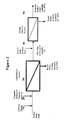
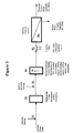
- the present invention comprises a resin component which is a highly macroporous resin that can be used for the pretreatment of water being fed to a membrane treatment system.
- the membrane treatment system may be a reverse osmosis membrane system or a nanofiltration membrane system.
- This resin component contains one or more ion exchange resin and/or adsorbent media layered or mixed together in an ion exchange vessel.
- the resin component can be described as a multi-contaminant control mixture since multiple contaminants are removed from the water stream by the resin. These contaminants include, but are not limited to, colloids, dissolved organic matter, dissolved silica, and divalent and trivalent cations.
- the resin component may also include adsorbents.
- the above contaminants are reduced or removed. Even more preferably, three or more of the above contaminants are reduced or removed. Even more preferably, four or more of the above contaminants are reduced or removed. Most preferably, five or more of the above contaminants are reduced or removed.
- the number of contaminants removed by the resin component will depend on the identity and concentrations of contaminants in the raw water, and the other elements in the water purification system being used, such as a pretreatment filter.
- a single porous resin that reduces or removes colloidal contaminants is used.
- the resin component comprises a porous resin to reduce or remove colloidal contaminants and a strong base resin that removes dissolved organic contaminants.
- the resin component comprises a porous resin to reduce or remove colloidal contaminants, a strong base resin that removes dissolved organic contaminants, and an adsorbent media that removes dissolved silica.
- a porous resin to reduce or remove colloidal contaminants a strong base resin that removes dissolved organic contaminants
- an adsorbent media that removes dissolved silica.
- Two or more of the resins may have been previously combined, such as a resin combining organic removal and removal of colloidal contaminants.
- the resin component may contain two or more strong base resins.
- the resin component contains a strong acid component as a softener resin.
- the phrase "reduces contaminant” means that at least 25% of the measurable contaminant (or contaminants) is removed from the water stream. More preferably, at least 40% of the contaminant is removed. More preferably, at least 60% of the contaminant is removed. Even more preferably, at least 70% of the contaminant is removed, and even more preferably, at least 80% of the contaminant is removed. Most preferably, at least 90% or more of the contaminant concentration is removed when comparing the contaminant concentration in the inlet of the vessel or device compared to the outlet of the vessel or device.
- the phrase "removes contaminant” means that at least 95% of the measurable contaminant (or contaminants) is removed from the water stream. More preferably, at least 98% of the contaminant is removed. Even more preferably, at least 99% of the contaminant is removed, and even more preferably, at least 99,5% of the contaminant is removed. Most preferably, at least 99.9% or more of the contaminant concentration is removed when comparing the contaminant concentration in the inlet of the vessel or device compared to the outlet of the vessel or device.
- diameter and “size,” when referring to colloids, are both defined as the average diameter of the colloidal particles.
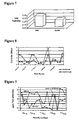
- the resin component is also effective for reducing the Silt Density Index (SDI) value of the water or process stream in preparation for treatment of the water by a reverse osmosis, nanofiltration, or similar membrane system.
- SDI value is a numeral value derived from a standard industry test in which the flowing sample of feed water to be tested is kept at a constant pressure of 30 psig and is passed through a 0.45-micron filter element. The time taken to fill a standard 500 ml container is recorded for an initial reading taken immediately at the beginning of the test and another reading taken 15 minutes after.
- a mathematical formula is used to compare and compute a numerical value referred to as the Silt Density Index (SDI) value.
- Numerical values range from 1 to 7, with 1 being excellent and representing minimum fouling, while increasing values represent rapidly deteriorating fouling conditions.
- the typical percentage of reduction of the SDI value of a water stream passing over the resin component ranges from 25% to 100%.
- the SDI is reduced by at least 40%. Even more preferably, the SDI is reduced by at least 50%, and even more preferably, the SDI is reduced by at least 60%. Even more preferably, the SDI is reduced by at least 70%, and even more preferably, the SDI is reduced by at least 80%. Even more preferably, the SDI is reduced by at least 90%, and most preferably, the SDI is reduced by at least 95%.
- the resin component uses a combination of two or more of:
- the resin component comprises a combination of a macroporous resin with high porosity and high crush strength and one or more of ii, iii, and iv.
- Macroporous resin of high porosity and high crush strength Macroporous resin of high porosity and high crush strength
- the macroporous resin used as part of the resin component is a colloidal scavenger resin with high porosity and high crush strength such as described in U.S. Pat. No. 6,323,249 to Dale, et al. , herein incorporated by reference.
- the diameter of the large macropores in this resin typically range from 5,000 to 100,000 Angstroms, or more preferably 10,000 to 200,000 Angstroms and are ideal for removal of colloidal particulates by a combination of adsorption and ion exchange phenomena.
- the mesh size of this resin is 16 to 50 U.S. mesh.
- Either cation or anion type resins can be utilized as the base resin. When using an anion resin as the base, the capacity for removal of dissolved organic matter is increased significantly.
- the synthesis of the macroporous resin of the present invention is described herein below.
- the macroporous resin also has a pore volume of at least 0.36 ml/g (dry).
- the pore volume may be greater than about 0.6 ml/g dry, or the pore volume may be between 0.36 and 1.5 ml/g dry.
- the macroporous resin has a high crush strength, which is defined as a Chatillon value of at least 24 g/bead (710 ⁇ m bead diameter). More preferably, the Chatillon value is at least 50 g/bead, and even more preferably at least 100 g/bead. More preferably, the Chatillon value is a least 200 g/bead.
- the high crush strength is an important aspect of the present invention since resins having lower crush strength have the disadvantage that, due to the need to contain and operate the resins in pressurized vessels and the need to subject the beads to repeated exhaustion and regeneration cycles, the beads tend to fracture. Potentially the fractured bead then can be eluted from the vessel and foul the membrane filter; the efficacy of the remaining resin is also reduced for resins having lower crush strength.
- the macroporous resin used as part of the resin component is an orthoporous resin with high porosity and high crush strength such as described in U.S. Provisional Patent Appl. No. 60/908,172 , herein incorporated by reference.
- the orthoporous resins used in the present invention have particularly large pores compared with typical macroporous resins. The pore size affects the diffusion and flow kinetics through the resin material.
- the orthoporous resins can be formed by generating an interpenetrating polymeric network (IPN). This is done by (a) preparing an initial macroporous copolymer, (b) re-swelling, and (c) polymerizing. When an orthoporous resin is used, the average pore diameter is between about 10,000 - 500,000 Angstroms.
- a first step involves the synthesis of a copolymer by (a) suspending droplets of a homogeneous mixture of monomers with a free radical initiator and porogen(s), such as an aliphatic alcohol -- i.e ., methyl isobutyl carbinol, isobutyl alcohol, etc.-(b) in an aqueous solution, and then (c) thermally polymerizing.
- a second step involves combining (reswelling) the 0 th order IPN, as made in the first step, with another monomer mixture and polymerizing in aqueous suspension, to create a 1 st order IPN.
- a third step combines the 1 st order IPN with additional monomer, to create a 2 nd order IPN.
- a 3 rd order IPN is formed by using the 2 nd order IPN as a seed.
- the mixture of polymerisable monomers used to form the copolymer and to form the IPN comprises a monoethylenically unsaturated monomer, or monomers, and a polyvinylidene monomer.
- Initiators, suspension agents, stabilizers, etc. may be added to the monomer mixture or aqueous phase as appropriate.
- One preferred macroporous resin is formed when styrene, divinylbenzene and a porogen are mixed together with a polymerization initiator to form the monomer solution.
- Free radical initiators are most desirable.
- Free radical generating compounds which may be used to effect polymerization of the monomers include peroxides such as benzoyl peroxide, lauoryl peroxide, tertiarybutyl peroxide, peroxy-compounds such as potassium persulfate, sodium perborate and ammonium persulfate and azo compounds such as azo-bisisobutyronitrile, 2,2-azobis-(2-methylbutyronitrile), 2-t-butylazo-2-cyano propane.
- Suitable concentrations are from 0.01 to 5.0%, more preferably 0.02 to 3.0%.
- the monomer phase is added to an aqueous phase for suspension polymerization of the monomers.
- Salt may be added to the aqueous phase to decrease the water solubility of the monomers.
- suspension agents and stabilizers such as polyvinylalcohol, methyl cellulose, carboxymethyl cellulose, hydroxyethyl cellulose, poly(vinyl pyrrolidine), polyacrylate salts, polymethyacrylate salts, dimethyldialkylammonium polymers, nitrite and dichromatic salts, calcium phosphate salts, carbonate salts, sulfate salts, bentonite clays, gum arabic, lignosulfonates, gelatine and xanthan gums in amounts ranging from 0.01 to 1.0% by weight of the monomers may be added to the aqueous dispersion to aid in maintaining the monomers dispersed as droplets while polymerizing the same as beads.
- polyvinylalcohol methyl cellulose, carboxymethyl cellulose, hydroxyethyl cellulose, poly(vinyl pyrrolidine)
- polyacrylate salts polymethyacrylate salts
- dimethyldialkylammonium polymers nitrite and di
- Orthoporous copolymers can be sulfonated with sulfuric acid, oleum, sulfur trioxide, or chlorosulfonic acid to form a cation exchanger or, alternatively, it may be chloroalkylated and subsequently aminated to form an anion exchanger.
- amines including primary, secondary, and tertiaryalkylamines, or arylamines can be employed in the amination reaction.
- Polyalkylenepolyamines such as ethylenediamine, diethylenetriamine, triethylenetetramine, tetraethylenepentamine, propylenediamine, and iminobispropylamine can also be used.
- Aminoalcohols and dimethylaminoethanol are also useful, as well as hexamethylenetetraamine.
- a preferred embodiment employs a trialkylamine as the aminating agent, producing a quaternary anion exchanger.
- the alkyl radical does not contain more than 4 carbon atoms.
- a strong base anion exchange using a trimethylamine resin is preferred.
- Weak base anion exchange resins may also be prepared; these resins are prepared in the same manner as the strong base resins with the exception that the tertiary-amine is replaced with non-tertiary amines, such as dimethylamine, diethylamine, monomethylamine, ethanol amines, etc.
- the macroporous resin described in this embodiment of the invention has a particularly high crush strength.
- the Chatillon value is at least 200 g/bead average (710 ⁇ m bead diameter). More preferably, the Chatillon value is at least 300 g/bead. More preferably, the Chatillon value is a least 400 g/bead.
- the crush strength is 475 g/bead.
- the high crush strength is an important aspect of the present invention since resins having lower crush strength have the disadvantage that, due to the need to contain and operate the resins in pressurized vessels and the need to subject the beads to repeated exhaustion and regeneration cycles, the beads tend to fracture. Potentially the fractured bead then can be eluted from the vessel and foul the membrane filter; the efficacy of the remaining resin is also reduced for resins having lower crush strength.
- an iron-impregnated or iron-containing media may be incorporated in the resin component.
- Granular iron oxide or iron hydroxide based adsorbents have been marketed for a number of years for arsenic removal and show a good capacity for dissolved silica adsorption, and may be used in the resin component of the present invention.
- preferred iron-impregnated or iron-containing media useful in the present invention includes iron-impregnated cation and anion resins such as ArsenX np (manufactured by The Purolite Co., Philadelphia) as described in U.S. Pat.
- the silica-containing water is simply passed through a bed of the iron-containing impregnated media, allowing the silica to diffuse into the matrix of the iron-impregnated resin to become complexed by adsorption onto the nanoparticles of iron oxide.
- ArsenX np resin was primarily developed for removal of arsenic and other oxyanions by adsorption, it shows good capacity for silica removal, like other iron-based adsorbents, but without the physical breakdown issues of granular products. Indeed, water treatment practitioners initially recognized the adsorption of silica by such iron-containing products during the removal of arsenic from drinking water systems. But to practitioners its ability to remove silica was viewed as merely providing undesirable competition to the adsorption of arsenic from the water since, depending on the water chemistry, ArsenX np resin typically shows adsorption capacities for silica of only about 1000 to 2000 bed volumes of water treated versus typical arsenic capacity of as much as 40,000 to 100,000 bed volumes.
- ArsenX np resin for silica has previously been viewed as more of a nuisance contaminant since the silica competed with arsenic, the contaminant of interest, for the same adsorption sites on the media.
- a proprietary method of regeneration of ArsenX np resin is available for stripping or eluting silica, phosphate, and arsenic from the media, utilizing simple brine and caustic solution consisting usually of 2% caustic and 1% brine. Heating the solution, preferably to temperatures up to 50°C, and passing 2 - 20 bed volumes, preferably approximately 6 bed volumes, slowly through the resin bed at a flowrate of about 2 bed volumes per hour increases the removal efficiency of silica and the other contaminants.
- ArsenX np can be used and disposed of after a single use, in a preferred embodiment, it is regenerated repeatedly after exhaustion and reused multiple of times before final disposal. This embodiment is desirable due to the lower overall cost. Therefore, ArsenX np resin is a preferred component in the resin component for processes where the raw water stream contains dissolved silica, especially at elevated concentrations. Iron-impregnated or iron-containing media having an iron oxide attached to an ion exchange resin where the ion exchange resin has a crush strength of at least 24 g/bead (and preferably higher) can be used for removal of dissolved silica in various systems that, because of the pressure requirements, do not allow for use of crushable medias. These systems include reverse osmosis systems, nanofiltration systems, demineralization units, cooling towers, boilers, etc.
- the resin component may contain, for example, a macroporous resin of high porosity and high crush strength, a strong base anion exchange resin, and ArsenX np resin.
- the resin component may contain two or more components from a single category. For example, it may contain two strong acid cation exchange resins for the removal of different metal cations. These components may be homogeneously mixed or formed into layers within the vessel containing the resin component. Other configurations of the components are also envisioned.
- the resin component must be able to withstand the pressure applied to the vessel without crushing.
- the crush strength of the macroporous resin within the resin component must be at least 24 g per bead average. More preferably, the crush strength is at least 50 g per bead. More preferably, the Chatillon value for the macroporous resin is a least 100 g per bead. Even more preferably, the Chatillon value for the macroporous resin is a least 200 g per bead average.
- the resin component which contains a macroporous resin and optionally other resins or absorbent components, has high crush strength, defined as a Chatillon value of at least 24 g per bead. More preferably, the Chatillon value for the resin component is at least 50g per bead. More preferably, the Chatillon value for the resin component is a least 100 g per bead. Even more preferably, the Chatillon value for the resin component is a least 200 g per bead.
- Commonly-used ion exchange resins such as strong-acid cation exchange resins and basic anion-exchange resins have crush strengths significantly greater than what is defined herein as a "high” crush strength.
- the adjective "high” is used, herein, to mean in comparison to other large-pore macroporous resins capable of adsorbing colloidal materials, and not all available or common resins without regard to their porosity.
- the resin component allows for the use of a smaller size RO membrane system for treating the same flow-rate of water compared to conventional systems; reduction in SDI by the methods and system of the present invention to values lower than 2 units, allows for design at a flux rate of 14 to 18 gallons per square foot of membrane surface per day (GFD) compared to the allowable flux of 8 to 14 GFD when SDI values exceed 2 units (see Hydranautics Design Limits, www.hydranautics.com/docs/trc/Dsgn_Lmt.pdf).
- GFD membrane surface per day
- the wastage is typically less than 1%, such as water used for periodic regeneration of the resin component compared to on-going backwash and flushing water needs of UF systems ranging from 5 to 15%.
- the use of the resin component in the methods and systems of the present invention also allows for the reduction in the number of unit operations or treatment steps needed compared to conventional treatment systems and in associated labor and operating costs.
- Additional benefits include a lower capital cost when compared to conventional and UF pretreatment systems, a reduced footprint requirement compared to conventional treatment systems, and the removal or reduction of contaminants that are not addressed by the conventional or UF pretreatment systems such as removal or reduction of dissolved sulfate, arsenate, phosphate, and similar oxyanions.
- An advantage of the method and system described in the present invention is the compact size available for the vessel containing the resin component.
- the resin component can use regenerable ion exchange/adsorbent resins layered or mixed together in a compact ion exchange vessel.
- the ability to use a vessel having a small footprint allows for lower cost vessels and smaller space requirements for the purification system without reducing the flow rate of the water in the system.
- Another advantage of the method and system described in the present invention is the lower cost associated with operating the purification process.
- an operator was generally required to oversee the process.
- a conventional hot lime softener/clarifier used to reduce silica contamination requires heating the water, a large space, and skilled operators to continuously monitor and adjust chemical feed.
- the purification technology described in US Patent Application 2002/0153319 requires a number of costly pretreatment steps including use of two weak acid cation vessels in series, one operating in the hydrogen form and the other in the sodium form, along with a decarbonator vessel to release CO 2 generated by the hydrogen form weak acid cation vessel.
- These units require on-going skilled operator attention on a daily basis for acid and caustic chemical handling and control, water sampling and testing.
- the resin component does not require significant operator oversight.
- Surface waters typically have elevated levels of suspended solids with turbidity values greater than 1 nephelometric turbidity units (NTU) and dissolved organic matter consisting largely of humic and fulvic acid compounds at concentrations of several parts per million.
- NTU nephelometric turbidity units
- colloidal particulates comprised of silt, clay, silica, iron, aluminum and organic matter.
- Silt Density Index values greater than 5.
- Typical concentrations of colloidal silica range from 0.2 to 3 ppm.
- the resin component of the present invention is particularly useful in removing these contaminants such that the fouling, chemical deposits, and chemical precipitation on the RO membrane are reduced.
- the resin component of the present invention is particularly useful in removing silica. Removal or reduction of dissolved silica in the feed water has always been of major interest in RO purification. Silica has a solubility of approximately 150 mg/l at ambient temperatures and can form difficult to remove deposits on the membrane surfaces if its solubility limit is exceeded in the reject/concentrate wastewater stream from RO system. Thus the higher the influent silica, the more reject water must be wasted. In fact, the need to prevent silica deposits and biological fouling are, in part, the major reasons for the large percentage of reject water from the typical RO system, ranging generally from 20 to 30%.
- Silica can be partially removed from surface waters in conventional hot lime softeners/clarifiers in which the silica is co-precipitated with magnesium hydroxide to form sludge.
- Such systems have not enjoyed widespread use however, since they are generally limited to large plants due to the requirements including heated water, a large space, and the need to continuously monitor and adjust the chemical feed.
- the exiting pH of the treated water, usually over 10 must be adjusted downward by acid addition to avoid post-precipitation of solids and to avoid damage to the RO membranes.
- the potential for fouling by colloidal particulates is increased as such systems have a tendency to retain colloidal and suspended solids in the carryover from the hot lime softener.
- the typical downstream multimedia can do a good job of removing suspended solids but has only minor capability to remove colloidal particulates, leaving the possibility of intolerable fouling of the membranes.
- Silica removal on iron oxide is a long established technology that has been used in purification of hot thermal brines, where an iron salt such as ferric chloride is used to form a sludge of iron oxide/hydroxide on which silica present in the brine is allowed to precipitate and is then filtered out.
- an iron salt such as ferric chloride
- the formation of an iron/silica sludge creates a similar problem to that formed with the hot lime softener, i.e ., the difficulty of efficiently filtering out suspended and colloidal solids before the water reaches the reverse osmosis membranes.
- the resin component of the present invention can be used to reduce dissolved silica in the feedwater to the membrane system, allowing a potential for recovery of a higher percentage of the water as permeate (approaching 85 to 95 percent), and thus requiring much less water to be wasted as reject.
- Silica in the reject stream must be controlled at no more than 150 ppm to avoid precipitation on the membrane surfaces. So for example, if the influent water had a silica content of 50 ppm, silica in the reject water can only be concentrated 3 times ( i.e. 150/50) so as not to exceed the 150 ppm limit; this equates to a rejection volume of 1/3 or approximately 33% of the water (if the small amount of silica leakage in the permeate is ignored).
- the pore structure of macroporous resins is formed by voids or channels between the polymer lattice work.
- the pore structure has been found to have a characteristic pore distribution and range. Numerous methods of pore measurement have been applied to macroporous resins; none are truly absolute. Characterization by the mercury-intrusion technique, particularly within a series, has been found to be direct, reproducible, and consistent. The mercury-intrusion method has long been used to find the distribution of sizes of capillary pores in a porous solid by forcing in mercury, the radius being found from the pressure and the percentage from the volume of mercury absorbed at each pressure.
- the method is based on the relationship that the pressure required to force pure mercury into a capillary of diameter d is (-4 ⁇ cos ⁇ )/d, where ⁇ is the surface tension of mercury and 0 is the contact angle of mercury with the porous solid ( Proc. Nat. Acad. Sci. U.S.A. (1921) 7:115 ). Since, for a particular solid the surface tension and the contact angle are constants, penetration of mercury into the pores, at a known pressure, indicates the corresponding pore diameter while the amount of mercury intruded, indicates the porosity or volume of pores of a given diameter.
- crush strength refers to the mechanical load required to break individual resin beads, and is used interchangeably with the term “friability.” Crush strength is the statistical average of the individual crush strengths of a sample comprising at least 10 but generally 25 beads, each bead having a particle diameter of 710 ⁇ m ⁇ 35 ⁇ m, wherein crush strength is the applied force at which the bead snaps or crushes.
- the crush strength of the macroporous resin of the present invention, when the resin has been aminated to form a strong base anion exchange resins is at least about 24 g/bead preferably at least 30 g/bead, more preferably at least 40 g/bead, and even more preferably at least 50 g/bead.
- the crush strength of the macroporous resin which has been formed into a strong acid-type cation exchange resins i.e ., sulfonic acid groups, e.g .
- sodium polystyrene sulfonate or poly AMPS sodium polystyrene sulfonate or poly AMPS
- other strong base resins i.e ., trimethylammonium groups (i.e ., polyAPTAC)
- weak acid resins i.e., carboxylic acid groups
- weak base resins i.e., amino groups, such as polyethylene amine
- Crush strength can be measured using the Chatillon test.
- the Chatillon test is named for an apparatus manufactured by John Chatillon and Sons, New York, N.Y. and designed to measure resin friability. This instrument measures the force (grams) required to crack or fracture a resin bead when it is placed between two parallel plates. The plates are gradually brought together at a uniform rate until the resin "breakpoint" is reached. The purpose of this test is to simulate the frictional and pressure forces exerted on individual resin beads under actual use conditions.
- Specifications for testing include converting the resin into the proper form (hydrogen or sodium for cation resins and chloride form for anion resins) by well known standard procedures.
- the converted resin is screened to a -20+30 U.S. mesh cut size and then allowed to fully hydrate in deionized water for at least 15 minutes prior to testing.
- Actual testing is done on a single resin bead (covered by a small drop of water) in the Chatillon instrument using the lowest practical speed of descent of the crushing plate.
- the individual fragmentation forces are recorded from the instrument in grams per bead and the results are presented as an average (20 beads minimum, typically 30 beads), a standard deviation, a 95% confidence interval, and the percentage of beads which meet a minimum friability standard.
- the propensity of a membrane to become fouled by particulates in the feed water can be determined using a standard test called the Silt Density Index (SDI).
- SDI Silt Density Index
- a sample of the feed water is passed through a 0.45-micron filter and a measurement is taken of how fast the filter becomes fouled. From this, an SDI value is calculated. Typical values range from 1 to 6. A high value means the water presents a high fouling risk.
- Membrane suppliers generally require an SDI value of no more than 4 if a performance guarantee is to be given, and generally prefer that the SDI value be no greater than 3.
- Properly designed conventional pretreatment systems generally achieve values below 5 and may sometimes achieve values or 3 or lower.
- NTU Nephelometric Turbidity Units
- the SDI of water exiting the vessel containing the resin component is less than 4. More preferably, it is less than 3.5, even more preferably, it is less than 3, and even more preferably, it is less than 2.5. In a preferred embodiment, the SDI is less than 2.0, and in an even more preferred embodiment, the SDI is less than 1.5, and in an even more preferred embodiment, the SDI is less than 1.0. Another method of analyzing the SDI is provided in a ratio of the SDI values for influent and effluent water of the vessel.
- An advantage of the resin component of the present invention is the simplicity of regeneration. This is found through the time saving, reduced operator costs, and in many cases, reduced cost of regenerant(s).
- chemical regenerant such as a mixture of sodium chloride and caustic soda
- all ion exchange resins and/or adsorbent media within the resin component are simultaneously regenerated or rejuvenated.
- the single regenerant is applied either at ambient or elevated temperatures up to 100°C.
- the chemical regenerant comprises a mixture of chloride salts, such as potassium, calcium or ammonium chloride, and an alkali or base, such as caustic potash, ammonium hydroxide, sodium carbonate, potassium carbonate, ammonium carbonate, and sesquicarbonates of sodium or potassium.
- chloride salts such as potassium, calcium or ammonium chloride
- alkali or base such as caustic potash, ammonium hydroxide, sodium carbonate, potassium carbonate, ammonium carbonate, and sesquicarbonates of sodium or potassium.
- the regenerant chemical comprises a chloride brine solution.
- the regenerant chemical comprises an alkali base.
- the resin component may be cleaned on a once- through basis.
- the regenerant mixture is passed once through the vessel containing the resin component and is then disposed of.
- Preferable flow rates range from 2 to 8 bed volumes per hour, a bed volume being defined as the equivalent liquid volume occupied by the combined volume resins and adsorbents in the vessel; even more preferred are flowrates ranging from 2 to 4 bed volumes per hour.
- regenerant mixture to regenerate all resins and adsorption medias results in savings on costs for regenerant, labor, associated dilution and rinse water, and waste water disposal costs including any chemical cost for neutralization of the alkali nature of the waste to comply with discharge regulations.
- the regenerant mixture may be re-used to regenerate the resin component in subsequent regenerations.
- a single regenerant mixture is used 2, 3, 4, 5, 6, 7, 8, 9, 10 or more times to clean the resin component when chemical cleaning is advised. Additional fresh chemicals may be added to the regenerant mixture for the subsequent regenerations to make up for any unavoidable losses to maintain the original concentration of the regenerant. While it is understood that re-using the regenerant mixture a certain number of times is not required each time it is advised to regenerate the resin component, it is noted that a greater ability to reuse the regenerant mixture allows for substantial cost saving.
- the ability to repeatedly reuse the regenerant mixture very significantly reduces the cost associated with operating the resin component system, including cost savings in chemical regenerant, associated labor, waste water disposal fees, and any chemicals needed to neutralize the alkali waste to comply with discharge regulations.
- the chemical regenerant is repeatedly recirculated through vessel containing the resin component, collecting the eluent from the vessel and using a pump to return the solution to the inlet of the vessel to again pass through the bed or volume of resin, and then repeating this procedure multiple of times.
- Preferred rates of recirculating the chemical regenerant are from 2 to 40 bed volumes per hour, with a more preferred rate ranging from 8 to 40 bed volumes per hour. Recirculation at higher rates than normally used in the single pass method of the recirculation allows for considerable savings in time, as well as savings in associated labor cost, and the operating flexibility to minimize the time during which the resin component vessel is unavailable for processing of the feed water to the membranes.
- the fraction of the contaminants left on the resin attains chemical equilibrium with the fraction extracted by the regenerant; a similar chemical equilibrium exists for the chemical regenerant, with the regenerant essentially displacing the contaminant from the resin in proportion to the selectivity of the resin for the contaminant and the regenerant.
- Demineralization of water is a reference base for the ion exchange process in which 95 to 99 percent of the dissolved solids present in the raw water must be removed.
- softening of water by ion exchange for use as boiler feedwater or for supply to RO systems requires removal of hardness to very low levels of about 1 part per million, typically representing about 99 percent removal from the raw water.
- it is intolerable to reuse or recirculate the regenerant if such quality is to be consistently achieved. Therefore, the embodiments comprising reuse and/or recirculation of the regenerant are not applicable to aspects of the invention in which strong acid cation resins in the sodium form are utilized for removal of divalent and trivalent cations, such as calcium and magnesium when softening for RO is required.
- the reuse and/or recirculation of the regenerant is appropriate for cases in which the resin component includes resins and/or adsorbents for the removal of dissolved silica, colloidal silica, and organic matter.
- the concentrations and quantities of alkali and brine used for regeneration represent a very large excess over stoichiometric requirements (a few hundred percent), and in such cases the percentage of contaminants removal achieved by the present invention (typically 25 to 75%) do not require the highest purity of regenerant to be used to achieve the targeted level of quality.
- extraction of silica from the resin component is greatly facilitated by the very high solubility of silica in a caustic soda solution (greater than 25 percent).
- Reuse of the regenerant is preferred embodiment of the invention as the operating cost of the resin component system can be reduced to a small fraction of the cost compared to using the regenerant just once, thus providing even more cost savings benefits over conventional pretreatment systems.
- Figure 1 shows the conventional pretreatment approach, utilizing a clarifier, multimedia filter, and carbon filter while Figure 2 shows the use of a UF membrane system as pretreatment.
- the conventional system such as the one described in Figure 1
- the UF pretreatment unit such as the one described in Figure 2
- the UF pretreatment unit is capital intensive and itself wastes significant amounts of water in addition to the waste from the RO itself.
- chlorine or sodium hypochlorite solution (refer to item 1 a) is usually dosed into the feed water at about 1 to 2 ppm free chlorine in order to control microbial growth.
- a coagulant such as aluminum sulfate (2a) and a polyelectrolyte polymer chemical (3a) are dosed in ppm concentrations ahead of the clarifier (4a) to create and to concentrate a gelatinous sludge of aluminum hydroxide. The large surface areas of the sludge can then trap any suspended and colloidal particulates present in the incoming surface water.
- the sludge is then routed to a quiescent zone of the clarifier where it is largely removed by settling to the bottom of the clarifier where it is periodically removed, then dried and disposed.
- Organic matters of the humic and fulvic acid varieties which are typically present in surface water are also partially removed by becoming trapped in the sludge produced by addition of the coagulant.
- any residual floating sludge that is carried over from the overflow of the clarifier is subsequently removed on the downstream multimedia filter (5a).
- Typical composition of the filter media are sand, anthracite and garnet, which generally provide more efficient filtration than a single media filter such as a sand filter.
- the water is then routed to an activated carbon filter (6a) for removal of any residual chlorine.
- activated carbon filter Most membranes have very limited tolerance for oxidizing agents such as chlorine and continuous exposure to even small concentrations can shorten their useful life significantly.
- the activated carbon also removes organic matter that is still present in the water at that step in the treatment process.
- the water is then finally routed through a 5 micron rated filter (8a) for removal of any last traces of suspended solids before it is fed to Reverse Osmosis System (9a).
- a 5 micron rated filter (8a) for removal of any last traces of suspended solids before it is fed to Reverse Osmosis System (9a).
- the goal at this point is to have water with maximum limits for turbidity and SDI values of 1 and 4 or better respectively.
- Routine tasks by operators would include refilling of chemical solutions for chlorine, coagulant, polymer, and acid or scale inhibitor; adjustment of chemical dosage for changes in the source water quality, calibration and repair of all chemical dosing systems, removal of sludge from the clarifier, backwash of the multimedia filters; periodic change out of micron filters and activated carbon media, observing, adjusting and recording of plant flow rates and periodic chemical cleaning of the membranes when they become fouled.
- FIG 2 shows the newer UF pretreatment system that is in use on especially larger RO systems.
- This system eliminates the use of the clarifier, multimedia, and activated carbon units as described in Figure 1 above.
- a coagulant (2b) is still dosed ahead of the UF system (3b) to more efficiently trap incoming organic matter.
- using a UF system transfers much of the problem of fouling by suspended solids, colloidal particulates, organic compounds, and biological matter from the RO unit to the UF unit. This means that the UF unit must be periodically backwashed and also chemically cleaned when the buildup of foulants causes too much of a decrease in operating efficiency.
- a significant problem is the waste of a portion of the incoming water used for periodic flushing of foulants from the surfaces of the membranes, with typical percentages ranging from 5 to 15% of the influent total being fed to the UF. This is in addition to the 20 to 30 percent of the water that is additionally wasted as reject from the downstream RO unit, amounting to total water losses ranging from 25 to 45%. While this is generally not a problem for desalination of seawater or municipal wastewater, it is a major concern to operators of RO plants in arid regions of the world where water supply is quite limited. Some membrane system suppliers offer a third smaller membrane system to further treat the reject stream from the first UF in an effort to reduce water losses. However, this adds further to the already larger extra capital costs needed for the main UF, making such systems affordable to only a limited number of users.
- the invention uses a compact small footprint multimedia vessel for simultaneous reduction of a variety of contaminants as described hereinabove, including colloidal particulates, the Silt Density Index value of the water, dissolved organic matter, metals, dissolved anions such as sulfate, arsenic, phosphate, and dissolved silica. It requires minimum operator attention, generates comparatively much smaller volume of waste water and the capital cost is significantly lower than that for either a UF or conventional pretreatment system.
- the embodiment described by Figure 3 when compared to the conventional system as described in Figure 1 , does not include the clarifier and activated carbon units, similar to the UF pretreatment system in Figure 2 above.
- Chlorine or sodium hypochlorite solution (refer to item 1c) is optionally dosed into the feed water at about 1 to 2 ppm free chlorine in order to control microbial growth. Any residual sludge or other suspended solids are removed on the downstream multimedia filter (2c).
- Typical, but non-limiting composition of the filter media include sand, anthracite and garnet, which generally provide more efficient filtration than a single media filter such as a sand filter.
- a resin component (4c) of one or more specialized ion exchange resins and/or adsorbent medias is installed downstream of the sodium bisulfite dosing point.
- the resin component contains a macroporous resin as described herein. Either cation or anion type resins can be used as the base resin. When an anion resin is used as the base, its capacity for removal of dissolved organic matter is increased significantly.
- the resin component (4c) is housed in a vessel.
- the vessel may be any container known in the art that can contain the resin component at the pressure required in the system.
- the water is then finally routed through a 5 micron rated filter (5c) or similar for removal of any last traces of suspended solids before it is fed to the Reverse Osmosis System (6c).
- the water fed to the RO system has a maximum limits for turbidity and SDI values of 1 and 4 or better respectively.
- a preferred embodiment of the present invention comprises the incorporation of an iron-impregnated or iron-containing media such as cation or anion resin, natural zeolite or alumina in the resin component (4c).
- a strong acid cation resin can be incorporated for removal of divalent and trivalent cations. After exhaustion, all resins can be regenerated with the same regenerant mixture of brine and caustic, either at ambient or elevated temperatures.
- Conventional gel resins formed by copolymerization of monovinylidene and polyvinylidene monomers contain micropores, where the pore structure is defined by the distance between the crosslinked polymeric chains.
- Macroporous resins contain significant non-gel porosity in addition to normal gel porosity, within the polymer lattice. This non-gel porosity arises from channels present between the gel lattices. These microscopic channels are separate and distinct from the micropores, which are present in all crosslinked copolymers, as is well known to those skilled in the art. While the channels are themselves relatively small, they are large when compared with the micropores of the gel type resins.
- the macroporous resins can be formed by the process described in U.S. Pat. 6,323,249 , herein incorporated by reference.
- the macroporous resins produced by the process described in U.S. Pat. 6,323,249 have extremely large-sized pores, but their narrower distribution of pore sizes gives them sufficiently high crush strength for most purposes.
- the narrower pore distribution, in the useful size range for the removal of colloidal matter, means that there are few uselessly small pores and needlessly large pores present.
- the macroporous resins are formed by copolymerizing monoethylenically unsaturated monomers with polyvinylidene monomers in the presence of mixture of relatively moderate amounts of a water-soluble polymeric porogen with a low molecular-weight, good swelling porogen.
- Useful monoethylenically unsaturated monomers include styrene, vinyltoluene, methyl-styrene, tertiary butyl styrene, vinyl pyridine, 2-methyl-5-vinyl pyridine, vinylidine chloride, tetrafluoroethylene, vinyl acetate, vinyl stearate, vinyl bromide, vinyl anisole, vinyl naphthalene, acrylic and methacrylic esters and other derivatives. Styrene is preferred.
- Useful polyvinylidene monomers for use as a crosslinking agent include divinylbenzene, diisopropenylbenzene, ethyleneglyocol dimethacrylate, hexanediol diacrylate, allyl methacrylate, divinyl ketone, divinyl sulfone, trimethylolpropane, trimethacrylate, and trivinylbenzene.
- Divinylbenzene is preferred, and is preferably present in an amount of from 2 to 100%, more preferably 2 to 16%.
- One preferred macroporous resin is formed when styrene, divinyl benzene and the porogen are mixed together with a polymerization initiator to form the monomer solution.
- Free radical initiators are most desirable.
- Free radical generating compounds which may be used to effect polymerization of the monomers include peroxides such as benzoyl peroxide, lauoryl peroxide, tertiary-butyl peroxide, hydrogen peroxide, per-compounds such as potassium persulfate, sodium perborate and ammonium persulfate and azocompounds such as azo-bisisobutyronitrile, 2,2-azobis-(2-methylbutyronitrile), 2-t-butylazo-2-cyano propane.
- Suitable concentrations are from 0.01 to 5.0%, more preferably 0.02 to 3.0%.
- the monomer phase is added to an aqueous phase for suspension polymerization of the monomers.
- Salt may be added to the aqueous phase to decrease the water solubility of the monomers.
- suspension agents and stabilizers such as polyvinylalcohol, methyl cellulose, carboxymethyl cellulose, hydroxyethyl cellulose, poly(vinyl pyrrolidine), polyacrylate salts, polymethyacrylate salts, dimethyldialkylammonium polymers, nitrite and dichromatic salts, calcium phosphate salts, carbonate salts, sulfate salts, bentonite clays, gum arabic, lignosulfonates, gelatine and xanthan gums in amounts ranging from 0.01 to 0.5% by weight of the monomers may be added to the aqueous dispersion to aid in maintaining the monomers dispersed as droplets while polymerizing the same as beads.
- polyvinylalcohol methyl cellulose, carboxymethyl cellulose, hydroxyethyl cellulose, poly(vinyl pyrrolidine)
- polyacrylate salts polymethyacrylate salts
- dimethyldialkylammonium polymers nitrite and di
- the crosslinked copolymer resin can be sulfonated with sulfuric acid, oleum, sulfur trioxide, or chlorosulfonic acid as the sulfonating agent to form a cation exchanger or, alternatively, it may be chloroalkylated and subsequently aminated to form-an anion exchanger.
- amines including primary, secondary, and tertiary alkylamines or arylamines can be employed in the amination reaction.
- Polyalkylenepolyamines such as ethylenediamine, diethylenetriamine, triethylenetetramine, tetraethylenepentamine and propylenediamine can also be used.
- Aminoalcohols and dimethylaminoethanol are also useful.
- a preferred embodiment employs a trialkylamine as the aminating agent, producing a quaternary anion exchanger.
- the alkyl radical does not contain more than 4 carbon atoms.
- a strong base anion exchange prepared with trimethylamine resin is preferred.
- resins with a strong base functionality are preferred for the removal of colloidal silica and other such colloidal particulate matter
- weak base anion exchange resins having the same macroporous structure will also perform.
- Such weak base anion exchange resins are prepared in the same manner as the strong base resins with the exception that the trimethylamine is replaced with dimethyl amine, diethyl amine, monomethyl amine, ethanol amines etc.
- These weak base anion exchange resins, aside from the differences in ion exchange functional groups, are essentially identical in morphological structure as the strong base anion exchange resins, particularly about their large pore sizes.
- the macroporous resin removes colloidal particulate matter, such as silica, from the water stream by providing novel macroporous resins characterized by pore diameter ranging in size from 4,000 to 500,000 Angstroms, or more preferably 4,000 to 200,000 Angstroms, or even more preferably from 10,000 to 200,000 Angstroms and having particularly high crush strength and high pore volume.
- the anion exchange resins can be used to remove colloids or particulate matter, such as colloidal silica or hydrous oxides, or can be used in conjunction with cation exchange resins to simultaneously achieve deionization and colloidal removal.
- the anion exchange resins of the invention are capable of effectively removing acids of relatively high molecular weight such as, for example, humic acid, and are capable of removing viruses from aqueous solutions.
- single chemical regenerant means both a single chemical regenerant and a mixture of chemicals using a single regenerant.
- highly macroporous resins means resins with pores with large diameters.
- the average pore diameter of a highly macroporous resin ranges at least about 1,000 Angstrom and typically has an average pore diameters (D50) of at least about 20,000 Angstroms.
- Orthoporous resins are highly macroporous resins having a substantial number of pore diameters ranging from 10,000 to 500,000 Angstroms.
- the term “simultaneous,” means at the same time or within a few minutes.
- “simultaneous regeneration or rejuvenation” means that the regeneration or rejuvenation occurs in a single process step by the addition of a single regenerant. It is understood that one chemical regeneration process may proceed at a different rate than another chemical regeneration process.
- the term 'about' or 'approximately' means within an acceptable error range for the particular value as determined by one of ordinary skill in the art, which will depend in part on how the value is measured or determined, i.e ., the limitations of the measurement system, i.e ., the degree of precision required for a particular purpose, such as a pharmaceutical formulation.
- “about” can mean within 1 or more than 1 standard deviations, per the practice in the art.
- “about” can mean a range of up to 20%, preferably up to 10%, more preferably up to 5%, and more preferably still up to 1% of a given value.
- the term can mean within an order of magnitude, preferably within 5-fold, and more preferably within 2-fold, of a value.
- the term "about” meaning within an acceptable error range for the particular value should be assumed.
- the invention was demonstrated using a continuously flowing surface water supply from a river with naturally varying composition with respect to colloidal silica, organics matter, turbidity and silt density index (SDI) values.
- the river water supply pretreatment system contained softening and clarification using chlorine, aluminum sulfate and calcium hydroxide, followed by sand filtration and activated carbon. Prior to use, the water was filtered through a 1-liter cartridge filter of spiral wound cotton fiber to remove suspended solids matter.
- the filtered water was then passed at a flowrate of 12 BV/H alternately through two 1 liter cartridges, each containing 1 liter of the resin component and comprised of a 50:50 mixture of Purolite A501P, a macroporous anion resin of high porosity and high crush strength as described in U.S. Patent No. 6,323,249 to Dale, et al. , and Purolite A-860, a macroporous acrylic strong base anion resin, both resins manufactured by Purolite Intl. Ltd.
- the influent water composition varied naturally; colloidal silica ranged from 0.5 to 4.5 ppm, dissolved organic matter ranged from 0.6 to 2.5 ppm, turbidity ranged from 0.2 to 0.65 NTU, and silt density index (SDI) ranged from 0.25 to 4.75 SDI units.
- Colloidal silica concentration, silt density index, concentration of organic matter, and turbidity were each measured at both the inlet and outlet of the ion exchange vessel.
- Figure 4 shows the average reduction in colloidal silica over the test period of approximately 50%, with colloidal silica being reduced from an average influent value of 1.5 ppm to an average effluent value of 0.75.
- Figure 5 shows the average reduction in the SDI from an average influent value of 3.0 to an average effluent value of approximately 1.5.
- Figure 6 shows the average reduction in dissolved organic matter from an average influent value of 0.92 ppm to an average effluent value of 0.25 ppm.
- Figure 7 shows the average reduction in turbidity from an influent value of 0.22 NTU to an average effluent value of approximately 0.15 NTU.
- Figures 8, 9 , 10 and 11 show the change in influent values and the corresponding changes in effluent values for colloidal silica, silt density index, organic matter, and turbidity respectively.
- the invention was demonstrated by treating Philadelphia city water supply containing approximately 2 ppm silica, a pH of 8.2, total dissolved solids of approximately 210 ppm, and a total organic matter content raging from 1.5 to 2.5 ppm measured as total organic carbon (TOC).
- the water was artificially spiked with additional silica to achieve 16.8 ppm of silica in keeping with typical levels experienced in many part of the United States where ROs are used with attendant silica deposition problems.
- the resin component comprising a 16 to 50 US mesh size sample of 1 liter of ArsenX np (with experimental code of D9908) was installed in a cartridge and the water was passed through the resin component at a flowrate of 12 bed volumes per hour.
- the influent and effluent dissolved silica concentration was measured periodically until the breakthrough of silica in the effluent reached 50 percent of the influent value as displayed in Figure 12 .
- a mass balance was done to determine the fraction of silica that was loaded on the resin.
- the total silica loaded on the resin was determined to be approximately 8 grams of silica per liter of resin.
- Water from the blowdown water stream of a 2400 psig steam generator boiler was recovered and treated for reuse by passing through a 1 liter cartridge filled with 1 liter of the resin component comprising ArsenX np (with experimental code D-9908) at a relatively flow rate of 57 bed volumes per hour.
- the blowdown water contained a very high concentration of silica at average of 77 parts per million and a relatively high pH of 9.5.
- the influent and effluent silica concentrations were measured periodically until the silica concentration in the effluent was approximately equal to that in the influent water.
- a mass balance was done to determine the fraction of silica that was loaded on the resin and this was determined to be approximately 6,000 milligrams of silica per liter of resin with a total of 161 liters of water treated as displayed in Figure 13 .
- the loading was 8.7 g SiO 2 per liter of media and a silica breakthrough of approximately 60% at the end of the test.
- Challenge solution was passed through the resin at a flow rate of 20 BV/H at ambient temperature.
- the challenge solution contained 51 ppm Ca, 17.8 ppm Mg, 114 ppm Na, 67 ppm SO 4 , 1.64 ppm PO 4 , 97.6 ppm HCO 3 , 140 ppm Cl, 22 ppm SiO 2 and had a pH of 7.7.
- Effluent samples were taken every 4 hours for a total time of 96 hours and the samples were analyzed for silica concentration and pH. The results are shown in Figure 14 , indicating a loading of approximately 17 grams of silica per liter of resin after 96 hours and a silica breakthrough of approximately 60% at the end of the test.
- Challenge solution was passed through the resin at a flow rate of 20 BV/H at ambient temperature.
- the challenge solution contained 46.8ppm Ca, 13.8 ppm Mg, 117 ppm Na, 60 ppm SO 4 , 0.01 ppm PO 4 , 125 ppm HCO 3 , 140 ppm Cl, 29 ppm SiO 2 and had a pH of 8.0.
- Effluent samples were taken every 4 hours for a total time of 96 hours and the samples analyzed for silica concentration and pH.
- This aspect of the invention was demonstrated using a continuously flowing surface water supply from a river with naturally varying composition with respect to colloidal silica, organics matter, turbidity and silt density index (SDI) values.
- the river water supply pretreatment system consisted of softening and clarification using chlorine, aluminum sulfate and calcium hydroxide, followed by sand filtration and activated carbon. Prior to use, the water was filtered through a 1-liter cartridge filter of spiral wound cotton fiber to remove suspended solids matter. The filtered water was then passed at a flowrate of 12 BV/H through the two cartridges for a total of 72 hours.
- the influent water composition varied naturally; colloidal silica ranged from 0.5 to 4.5 ppm, dissolved organic matter ranged from 0.6 to 2.5 ppm, turbidity ranged from 0.2 to 0.65 NTU, and silt density index (SDI) ranged from 0.25 to 4.75 SDI units. Colloidal silica concentration, silt density index, concentration of organic matter, and turbidity were each measured at both the inlet and outlet of the ion exchange vessel.
- regenerant solution comprised of a two step approach, with the first step comprised of 10% NaCl/2% NaOH at dosages of 160 grams/liter and 32 grams/liter respectively and heated to 40°C.
- the second step comprised a solution of just 10% NaCl at a dosage of 64 grams/liter at ambient temperature. Average reduction in colloidal silica, SDI and organic matter were 62%, 44% and 75% respectively ( i.e ., 40C Alk. Brine, Brine (4 reg)).
- the reduction of organic matter after multiple loading and regeneration cycles is similar for each of the tested regenerants.
- regeneration using 40C brine is the best, and alkali brine also good.
- regeneration using alkali brine and brine is the most preferred. While temperature control is not needed, extra brine step is helpful.
Landscapes
- Life Sciences & Earth Sciences (AREA)
- Hydrology & Water Resources (AREA)
- Engineering & Computer Science (AREA)
- Environmental & Geological Engineering (AREA)
- Water Supply & Treatment (AREA)
- Chemical & Material Sciences (AREA)
- Organic Chemistry (AREA)
- Separation Using Semi-Permeable Membranes (AREA)
- Treatment Of Water By Ion Exchange (AREA)
- Water Treatment By Sorption (AREA)
- Addition Polymer Or Copolymer, Post-Treatments, Or Chemical Modifications (AREA)
Claims (12)
- Verfahren zur Reinigung von Wasser, kolloidale, partikuläre Stoffe enthaltend, Folgendes umfassend:a) Vorbehandeln des Wassers, indem das Wasser durch ein eine Harzkomponente enthaltendes Behältnis geleitet wird, wobei die Harzkomponente ein hoch makroporöses Anionenaustauschharz umfasst, welches eine beträchtliche Menge an Poren mit einem Porendurchmesser im Bereich von 4.000 bis 500.000 Ängström und eine Druckfestigkeit bzw. einen Chatillon-Wert von mindestens 24 g/Korn (710 µm Kornndurchmesser) umfasst;b) Zuführen des Wassers, das aus der Harzkomponente austritt, zu einer Umkehrosmosemembran bzw. Nanofiltrationsmembran, um Permeatwasser zu erzeugen; undc) Regenerieren der Harzkomponente in periodischen Abständen, indem Verunreinigungen von dem Harz entfernt werden, indem eine Natriumchloridlösung durch das Behältnis geleitet wird, wobei das Wasser, das in das Behältnis fließt, einem Druck von 5 bis 200 Pfund pro Quadratzoll (0,345 bis 13,789 bar) ausgesetzt wird, die Harzkomponente den Gehalt an kolloidalen, partikulären Stoffen sowie den Silt-Density-Index- (SDI-) Gehalt des Wassers um mindestens 20 Prozent der Zuflusswerte reduziert, und der Wasserfluss von der Harzkomponente zur Umkehrosmose- bzw. Nanofiltrationsmembran stetig ist.
- Verfahren nach Anspruch 1, wobei das makroporöse Harz ein Porenvolumen von mindestens 0,36 ml/g (trocken) aufweist.
- Verfahren nach Anspruch 1, wobei das makroporöse Harz aus der Polymerisation einer Lösung aus (a) einem monoethylenischen Monomer, (b) einem polyethylenischen Monomer, (c) einem Radikalinitiator und (d) einem porenbildenden Reagens aus 20-40-pph-Poly(alkylenoxid) oder einer Mischung aus dem porenbildenden Reagens aus 20-40-pph-Poly(alkylenoxid) mit Toluen gebildet wird.
- Verfahren nach Anspruch 1, wobei das makroporöse Harz eine Druckfestigkeit bzw. einen Chatillon-Wert von 175 g/Korn bis 475 g/Korn aufweist.
- Verfahren nach Anspruch 2, wobei das makroporöse Harz einen durchschnittlichen Porendurchmesser im Bereich von 10.000 bis 500.000 Ängström, ein Porenvolumen von mindestens 0,60 ml/g (trocken) und eine Druckfestigkeit bzw. einen Chatillon-Wert von mindestens 24 g/Korn aufweist; und
vorzugsweise einen Porendurchmesser im Bereich von 10.000 bis 200.000 Ångström, ein Porenvolumen von mindestens 0,60 ml/g (trocken) und eine Druckfestigkeit bzw. einen Chatillon-Wert von mindestens 24 g/Korn aufweist. - Verfahren nach Anspruch 1, wobei das makroporöse Harz einen Porendurchmesser im Bereich von 5.000 bis 100.000 Ångström; ein Porenvolumen von mindestens 0,60 ml/g (trocken) und eine Druckfestigkeit bzw. einen Chatillon-Wert von mindestens 24 g/Korn bis 175 g/Korn aufweist.
- Verfahren nach Anspruch 1, wobei das makroporöse Harz einer Chloromethylierung unterzogen und anschließend belebt wird.
- Verfahren nach Anspruch 1, wobei das Regenerieren ein erneutes Zirkulieren des Natriumchlorids umfasst, indem der Abfluss von dem die Harzkomponente enthaltenden Behältnis aufgefangen und erneut in das Behältnis hinein geleitet wird, damit wiederholte Durchgänge durch die Harzkomponente erfolgen.
- Verfahren nach Anspruch 1, wobei die Harzkomponente ferner ein auf einer Polystyrolmatrix oder einer Acrylpolymermatrix basierendes Anionenaustauschharz, jedoch mindestens eines davon, umfasst.
- Verfahren nach Anspruch 1, wobei die Harzkomponente ferner ein oder mehrere stark basische Harze umfasst.
- Verfahren nach Anspruch 1, wobei die Harzkomponente den Gehalt an TOC (Gesamtmenge an organisch gebundenem Kohlenstoff), den das aufbereitete Wasser aufweist, um mindestens 20 % verringert.
- Verfahren nach Anspruch 1, wobei die Natriumchloridlösung der Harzkomponente bei einer Geschwindigkeit von 2 bis 20 Bettvolumen pro Stunde hinzugefügt wird, wobei das Bettvolumen das entsprechende Flüssigkeitsvolumen darstellt, das von dem Harz in dem Behältnis umfasst wird.
Applications Claiming Priority (3)
| Application Number | Priority Date | Filing Date | Title |
|---|---|---|---|
| US88585507P | 2007-01-19 | 2007-01-19 | |
| US90817207P | 2007-03-26 | 2007-03-26 | |
| PCT/US2008/051222 WO2008089279A1 (en) | 2007-01-19 | 2008-01-16 | Reduced fouling of reverse osmosis membranes |
Publications (2)
| Publication Number | Publication Date |
|---|---|
| EP2111380A1 EP2111380A1 (de) | 2009-10-28 |
| EP2111380B1 true EP2111380B1 (de) | 2015-10-28 |
Family
ID=39467264
Family Applications (1)
| Application Number | Title | Priority Date | Filing Date |
|---|---|---|---|
| EP08727779.4A Not-in-force EP2111380B1 (de) | 2007-01-19 | 2008-01-16 | Verminderter bewuchs von umkehrosmosemembranen |
Country Status (6)
| Country | Link |
|---|---|
| US (1) | US8883012B2 (de) |
| EP (1) | EP2111380B1 (de) |
| JP (1) | JP5172859B2 (de) |
| CN (1) | CN101646628B (de) |
| BR (1) | BRPI0806375A2 (de) |
| WO (1) | WO2008089279A1 (de) |
Families Citing this family (44)
| Publication number | Priority date | Publication date | Assignee | Title |
|---|---|---|---|---|
| ZA200708565B (en) * | 2005-04-08 | 2009-04-29 | Dow Global Technologies Inc | Alkaline regeneration of N-Methyl-D-glucamine functional resins |
| US20090039018A1 (en) * | 2007-08-08 | 2009-02-12 | Jordi Howard C | Suspension homopolymerization of an isocyanurates |
| EP2075070A1 (de) * | 2007-12-13 | 2009-07-01 | BP Chemicals Limited | Verfahren zur Katalysatorrückgewinnung |
| JP5608988B2 (ja) * | 2009-02-27 | 2014-10-22 | 栗田工業株式会社 | 活性炭用スライムコントロール剤、活性炭装置への通水方法、有機物含有水の処理方法及び処理装置 |
| FR2958929B1 (fr) * | 2010-04-19 | 2013-07-05 | Otv Sa | Procede de traitement d'eau en vue de son dessalement incluant une filtration a grande vitesse, et installation correspondante. |
| WO2011147019A1 (en) | 2010-05-26 | 2011-12-01 | Al-Samadi Riad A | Multi-use high water recovery process |
| US9216385B2 (en) | 2010-10-04 | 2015-12-22 | Saudi Arabian Oil Company | Application of rejection enhancing agents (REAs) that do not have cloud point limitations on desalination membranes |
| JP5798908B2 (ja) * | 2011-12-19 | 2015-10-21 | 株式会社日立製作所 | 逆浸透処理装置および逆浸透処理装置の洗浄方法 |
| JP2013180234A (ja) * | 2012-03-01 | 2013-09-12 | Hitachi Ltd | 淡水化システムおよび淡水化処理方法 |
| US20130313199A1 (en) * | 2012-05-23 | 2013-11-28 | High Sierra Energy, LP | System and method for treatment of produced waters |
| AU2013204708B2 (en) * | 2012-05-25 | 2016-11-03 | Ixom Operations Pty Ltd | Water Treatment Process |
| US9475717B2 (en) | 2012-08-23 | 2016-10-25 | Total Water Treatment Systems, Inc. | Water purification system engineered for legionella control in industrial and commercial water systems |
| US20140110316A1 (en) * | 2012-10-22 | 2014-04-24 | Eco Watertech, Inc. | Flow Through Adsorber for TDS Ablation |
| CN103011458A (zh) * | 2012-12-19 | 2013-04-03 | 无锡恩奈迪环保设备有限公司 | 一种高浓度富马酸废水资源化处理系统 |
| US10906001B2 (en) * | 2013-01-18 | 2021-02-02 | Chevron U.S.A. Inc. | Methods and systems for treating high temperature produced water |
| KR20160039602A (ko) * | 2013-06-04 | 2016-04-11 | 바스프 에스이 | 폐수 중의 총 유기 탄소의 감소 방법 |
| JP5700080B2 (ja) * | 2013-07-02 | 2015-04-15 | 栗田工業株式会社 | カチオン界面活性剤含有排水の処理方法及び処理装置 |
| WO2015041866A1 (en) * | 2013-09-18 | 2015-03-26 | Purolite Corporation | Resin regeneration method for reducing organic contaminants |
| CN103739127B (zh) * | 2013-12-12 | 2016-07-06 | 中冶海水淡化投资有限公司 | 控制反渗透膜生物污染的海水预处理方法及系统 |
| FR3015969A1 (fr) * | 2013-12-26 | 2015-07-03 | Veolia Water Solutions & Tech | Procede et installation de traitement d'eau sur membranes de nanofiltration ou d'osmose inverse permettant de reduire l'encrassement biologique de celles-ci. |
| CN103663798B (zh) * | 2013-12-30 | 2015-04-22 | 南京大学 | 印染废水二级处理出水的梯级处理与回用方法 |
| JP6497843B2 (ja) * | 2014-01-30 | 2019-04-10 | 三菱重工エンジニアリング株式会社 | 逆浸透膜へのケミカルファウリング防止システム及び方法 |
| US10882773B1 (en) | 2014-02-25 | 2021-01-05 | Waterfleet, LLC | Water purification system |
| JP5867532B2 (ja) * | 2014-03-18 | 2016-02-24 | 栗田工業株式会社 | 水処理用分散剤及び水処理方法 |
| JP6532471B2 (ja) * | 2014-09-11 | 2019-06-19 | 三菱重工エンジニアリング株式会社 | 水処理装置及び水処理方法 |
| US20180036686A1 (en) * | 2015-02-23 | 2018-02-08 | Mitsubishi Heavy Industries, Ltd. | Water quality monitoring device, water treatment device, water treatment system, water quality monitoring method, and program |
| CN104801195A (zh) * | 2015-04-30 | 2015-07-29 | 浙江农林大学 | 清洗反渗透膜及纳滤膜有机物污染的新方法 |
| DE102015111413B4 (de) * | 2015-07-14 | 2022-03-31 | Grünbeck Wasseraufbereitung GmbH | Vorrichtung zur Wasserbehandlung sowie Verfahren zur Regenerierung einer Wasserbehandlungsvorrichtung |
| KR101745146B1 (ko) | 2015-10-05 | 2017-06-08 | 대림산업 주식회사 | 산화철 다이나믹 막여과를 이용한 해수 담수화 장치 및 방법 |
| US10155203B2 (en) * | 2016-03-03 | 2018-12-18 | Lg Nanoh2O, Inc. | Methods of enhancing water flux of a TFC membrane using oxidizing and reducing agents |
| CN106323689B (zh) * | 2016-08-22 | 2020-02-21 | 中国食品发酵工业研究院有限公司 | 一种以水质监测为导向的痕量极性有机污染物捕集器 |
| EP3512813B1 (de) * | 2016-09-15 | 2024-11-06 | Fluence Water Israel Ltd | Containerisiertes entsalzungssystem |
| CN106519288B (zh) * | 2016-11-09 | 2019-01-01 | 绍兴文理学院 | 一种大比表面积,磺酸根功能化的大孔树脂的制备方法 |
| US11377379B2 (en) | 2018-05-01 | 2022-07-05 | DDP Specialty Electronic Materials US, Inc. | Water treatment |
| MX2021001682A (es) * | 2018-08-14 | 2021-05-31 | 1441413 Alberta Inc Dba Ept | Medios sumamente porosos para el acondicionamiento y rehabilitacion de lubricantes. |
| CN113164842A (zh) * | 2018-11-20 | 2021-07-23 | 维克多创新产品公司 | 供水装置及相关方法 |
| FR3098511B1 (fr) * | 2019-07-12 | 2021-12-03 | Veolia Water Solutions & Tech | Procédé de traitement d’eaux destiné à abattre leur teneur en silice dissoute |
| WO2021231114A1 (en) * | 2020-05-11 | 2021-11-18 | Ddp Specialty Electronic Materials Us, Llc | Sulfonated polystyrene nonwoven |
| CN112142168B (zh) * | 2020-09-18 | 2022-06-03 | 中国南方电网有限责任公司超高压输电公司天生桥局 | 改善换流阀外冷水系统膜污染的阳极材料和电化学方法 |
| CN116929897B (zh) * | 2022-04-11 | 2025-03-28 | 山东省食品药品检验研究院 | 一种肉中寄生虫检测装置及肉片渗透压差预处理设备 |
| US20240254016A1 (en) * | 2023-01-27 | 2024-08-01 | ACWA POWER Company | System configuration for seawater reverse osmosis (swro) for higher recovery operations and lower fouling propensity |
| CN116002933B (zh) * | 2023-03-24 | 2023-06-09 | 成都之和环保科技有限公司 | 一种纯水的制备方法 |
| WO2025075943A1 (en) * | 2023-10-02 | 2025-04-10 | Chemtreat, Inc. | Antiscalant treatments for water that is processed to remove organic contaminants |
| GB2639526A (en) * | 2023-12-20 | 2025-10-01 | Biofuel Solutions Ltd | Filtration process following thermochemical treatment of biomass |
Family Cites Families (22)
| Publication number | Priority date | Publication date | Assignee | Title |
|---|---|---|---|---|
| US3454493A (en) * | 1966-08-01 | 1969-07-08 | Rohm & Haas | Process and product for removing colloidal materials from aqueous media |
| JPS5188473A (en) * | 1975-01-31 | 1976-08-03 | Suichuno keisanjokyohoho | |
| JPS5262183A (en) * | 1975-11-18 | 1977-05-23 | Ebara Infilco Co Ltd | Method of desalting brine |
| US4076622A (en) * | 1976-06-22 | 1978-02-28 | Rohm And Haas Company | Microbiocidal macroreticular ion exchange resins, their method of preparation and use |
| US4895659A (en) * | 1987-04-30 | 1990-01-23 | Regents Of The University Of Minnesota | Method for metal and cyanide recovery from plating baths and rinse waters |
| US6323249B1 (en) * | 1988-09-26 | 2001-11-27 | Purolite International, Ltd. | Macroporous resins having large pores but with high crush strength |
| US4969991A (en) * | 1989-08-30 | 1990-11-13 | Valadez Gerardo M | Water purifying and dispensing system |
| JPH0790219B2 (ja) * | 1990-08-01 | 1995-10-04 | 日本錬水株式会社 | 純水製造装置及び製造方法 |
| JPH0771669B2 (ja) * | 1990-08-29 | 1995-08-02 | 日本錬水株式会社 | 超純水の製造法 |
| JP2950621B2 (ja) * | 1990-12-06 | 1999-09-20 | オルガノ株式会社 | 超純水の製造方法 |
| JP2677468B2 (ja) * | 1991-10-04 | 1997-11-17 | オルガノ株式会社 | 純水の製造方法及び装置 |
| US5512604A (en) * | 1992-08-28 | 1996-04-30 | The Dow Chemical Company | Porous copolymers having a cellular polymeric structure suitable for preparing ion-exchange resins and adsorbents |
| US5374357A (en) * | 1993-03-19 | 1994-12-20 | D. W. Walker & Associates | Filter media treatment of a fluid flow to remove colloidal matter |
| US20020153319A1 (en) | 1997-08-12 | 2002-10-24 | Debasish Mukhopadhyay | Method and apparatus for high efficiency reverse osmosis operation |
| US6258278B1 (en) * | 1997-03-03 | 2001-07-10 | Zenon Environmental, Inc. | High purity water production |
| US20020152219A1 (en) * | 2001-04-16 | 2002-10-17 | Singh Monmohan L. | Data interexchange protocol |
| JP4139333B2 (ja) * | 2001-11-09 | 2008-08-27 | キネティック バイオシステムズ インコーポレイテッド | クロマトグラフィー用の方法及び組成物 |
| JP4011440B2 (ja) * | 2002-08-28 | 2007-11-21 | オルガノ株式会社 | イオン吸着モジュール及び水処理方法 |
| TW200426117A (en) * | 2002-12-18 | 2004-12-01 | Rohm & Haas | Water treatment system with low waste volume |
| DE10327111A1 (de) * | 2003-06-13 | 2004-12-30 | Bayer Chemicals Ag | Vorrichtung zum Aufarbeiten von Wasser mittels Eisendotierter Ionenaustauscher |
| US20040262206A1 (en) * | 2003-06-27 | 2004-12-30 | Doug Gettman | Mobile field electrical supply, freshwater and saltwater purification system, powder wash, wash station, and water collection and reclamation apparatus |
| US7291578B2 (en) * | 2004-01-21 | 2007-11-06 | Arup K. Sengupta | Hybrid anion exchanger for selective removal of contaminating ligands from fluids and method of manufacture thereof |
-
2008
- 2008-01-16 WO PCT/US2008/051222 patent/WO2008089279A1/en not_active Ceased
- 2008-01-16 EP EP08727779.4A patent/EP2111380B1/de not_active Not-in-force
- 2008-01-16 JP JP2009546498A patent/JP5172859B2/ja active Active
- 2008-01-16 CN CN2008800021890A patent/CN101646628B/zh active Active
- 2008-01-16 BR BRPI0806375-3A patent/BRPI0806375A2/pt not_active IP Right Cessation
- 2008-01-16 US US12/015,429 patent/US8883012B2/en active Active
Also Published As
| Publication number | Publication date |
|---|---|
| CN101646628A (zh) | 2010-02-10 |
| CN101646628B (zh) | 2013-01-16 |
| EP2111380A1 (de) | 2009-10-28 |
| BRPI0806375A2 (pt) | 2011-09-13 |
| WO2008089279A1 (en) | 2008-07-24 |
| JP2010516450A (ja) | 2010-05-20 |
| US20080173583A1 (en) | 2008-07-24 |
| JP5172859B2 (ja) | 2013-03-27 |
| US8883012B2 (en) | 2014-11-11 |
Similar Documents
| Publication | Publication Date | Title |
|---|---|---|
| EP2111380B1 (de) | Verminderter bewuchs von umkehrosmosemembranen | |
| US20160229711A1 (en) | Resin regeneration method for reducing organic contaminants | |
| Al Abdulgader et al. | Hybrid ion exchange–Pressure driven membrane processes in water treatment: A review | |
| Comstock et al. | Combined magnetic ion exchange and cation exchange for removal of DOC and hardness | |
| CA2199497C (en) | Water treatment process | |
| US8496121B2 (en) | Macroporous copolymers with large pores | |
| JP7132932B2 (ja) | 超純水を製造するための方法 | |
| AU2013204708B2 (en) | Water Treatment Process | |
| CA2857053C (en) | Process for treating water by removing ions and filtering agglomerates through a sorbent bed | |
| JP2020507462A (ja) | 超純水を製造するための方法 | |
| Bornak | Desalination by ion exchange | |
| Meyers | Behavior of silica in ion exchange and other systems | |
| US20060283803A1 (en) | Water treatment process | |
| US7935260B2 (en) | Filtering systems and methods characterized by reduced color throw | |
| Hilal et al. | Enhanced membrane pre‐treatment processes using macromolecular adsorption and coagulation in desalination plants: a review | |
| JP2008062223A (ja) | 膜ろ過方法及び膜ろ過処理システム | |
| DK2850034T3 (en) | Ion exchange method with piston flow conditions and short residence times | |
| Wang et al. | Ion exchange engineering fundamentals | |
| CN117083249A (zh) | 用树脂处理工业废水中的有机化合物的方法 | |
| Gibert et al. | Composition and reversibility of fouling on low-pressure membranes in the filtration of coagulated water: insights into organic fractions behaviour | |
| JP3674368B2 (ja) | 純水製造方法 | |
| JP3941006B2 (ja) | シリカ除去装置及びシリカ含有水の処理方法 | |
| JP2007117997A (ja) | 膜ろ過システム、膜ろ過方法 | |
| Jamaly | Ultrafiltration Membrane Fouling and the Effect of Ion Exchange Resins |
Legal Events
| Date | Code | Title | Description |
|---|---|---|---|
| PUAI | Public reference made under article 153(3) epc to a published international application that has entered the european phase |
Free format text: ORIGINAL CODE: 0009012 |
|
| 17P | Request for examination filed |
Effective date: 20090819 |
|
| AK | Designated contracting states |
Kind code of ref document: A1 Designated state(s): AT BE BG CH CY CZ DE DK EE ES FI FR GB GR HR HU IE IS IT LI LT LU LV MC MT NL NO PL PT RO SE SI SK TR |
|
| RIN1 | Information on inventor provided before grant (corrected) |
Inventor name: DE SOUSA, FABIO, CHAVES Inventor name: IESAN, CARMEN, MIHAELA Inventor name: DALE, JAMES, A. Inventor name: BOODOO, FRANCIS |
|
| 17Q | First examination report despatched |
Effective date: 20100205 |
|
| DAX | Request for extension of the european patent (deleted) | ||
| GRAP | Despatch of communication of intention to grant a patent |
Free format text: ORIGINAL CODE: EPIDOSNIGR1 |
|
| RIN1 | Information on inventor provided before grant (corrected) |
Inventor name: DALE, JAMES, A. Inventor name: BOODOO, FRANCIS Inventor name: DE SOUSA, FABIO, CHAVES Inventor name: IESAN, CARMEN, MIHAELA |
|
| INTG | Intention to grant announced |
Effective date: 20150507 |
|
| GRAS | Grant fee paid |
Free format text: ORIGINAL CODE: EPIDOSNIGR3 |
|
| GRAA | (expected) grant |
Free format text: ORIGINAL CODE: 0009210 |
|
| AK | Designated contracting states |
Kind code of ref document: B1 Designated state(s): AT BE BG CH CY CZ DE DK EE ES FI FR GB GR HR HU IE IS IT LI LT LU LV MC MT NL NO PL PT RO SE SI SK TR |
|
| REG | Reference to a national code |
Ref country code: GB Ref legal event code: FG4D |
|
| REG | Reference to a national code |
Ref country code: CH Ref legal event code: EP |
|
| REG | Reference to a national code |
Ref country code: AT Ref legal event code: REF Ref document number: 757834 Country of ref document: AT Kind code of ref document: T Effective date: 20151115 |
|
| REG | Reference to a national code |
Ref country code: IE Ref legal event code: FG4D |
|
| REG | Reference to a national code |
Ref country code: DE Ref legal event code: R096 Ref document number: 602008040880 Country of ref document: DE |
|
| REG | Reference to a national code |
Ref country code: LT Ref legal event code: MG4D |
|
| REG | Reference to a national code |
Ref country code: NL Ref legal event code: MP Effective date: 20151028 |
|
| REG | Reference to a national code |
Ref country code: AT Ref legal event code: MK05 Ref document number: 757834 Country of ref document: AT Kind code of ref document: T Effective date: 20151028 |
|
| PG25 | Lapsed in a contracting state [announced via postgrant information from national office to epo] |
Ref country code: LT Free format text: LAPSE BECAUSE OF FAILURE TO SUBMIT A TRANSLATION OF THE DESCRIPTION OR TO PAY THE FEE WITHIN THE PRESCRIBED TIME-LIMIT Effective date: 20151028 Ref country code: IT Free format text: LAPSE BECAUSE OF FAILURE TO SUBMIT A TRANSLATION OF THE DESCRIPTION OR TO PAY THE FEE WITHIN THE PRESCRIBED TIME-LIMIT Effective date: 20151028 Ref country code: ES Free format text: LAPSE BECAUSE OF FAILURE TO SUBMIT A TRANSLATION OF THE DESCRIPTION OR TO PAY THE FEE WITHIN THE PRESCRIBED TIME-LIMIT Effective date: 20151028 Ref country code: NL Free format text: LAPSE BECAUSE OF FAILURE TO SUBMIT A TRANSLATION OF THE DESCRIPTION OR TO PAY THE FEE WITHIN THE PRESCRIBED TIME-LIMIT Effective date: 20151028 Ref country code: IS Free format text: LAPSE BECAUSE OF FAILURE TO SUBMIT A TRANSLATION OF THE DESCRIPTION OR TO PAY THE FEE WITHIN THE PRESCRIBED TIME-LIMIT Effective date: 20160228 Ref country code: HR Free format text: LAPSE BECAUSE OF FAILURE TO SUBMIT A TRANSLATION OF THE DESCRIPTION OR TO PAY THE FEE WITHIN THE PRESCRIBED TIME-LIMIT Effective date: 20151028 Ref country code: NO Free format text: LAPSE BECAUSE OF FAILURE TO SUBMIT A TRANSLATION OF THE DESCRIPTION OR TO PAY THE FEE WITHIN THE PRESCRIBED TIME-LIMIT Effective date: 20160128 |
|
| PG25 | Lapsed in a contracting state [announced via postgrant information from national office to epo] |
Ref country code: GR Free format text: LAPSE BECAUSE OF FAILURE TO SUBMIT A TRANSLATION OF THE DESCRIPTION OR TO PAY THE FEE WITHIN THE PRESCRIBED TIME-LIMIT Effective date: 20160129 Ref country code: PL Free format text: LAPSE BECAUSE OF FAILURE TO SUBMIT A TRANSLATION OF THE DESCRIPTION OR TO PAY THE FEE WITHIN THE PRESCRIBED TIME-LIMIT Effective date: 20151028 Ref country code: BE Free format text: LAPSE BECAUSE OF NON-PAYMENT OF DUE FEES Effective date: 20160131 Ref country code: FI Free format text: LAPSE BECAUSE OF FAILURE TO SUBMIT A TRANSLATION OF THE DESCRIPTION OR TO PAY THE FEE WITHIN THE PRESCRIBED TIME-LIMIT Effective date: 20151028 Ref country code: AT Free format text: LAPSE BECAUSE OF FAILURE TO SUBMIT A TRANSLATION OF THE DESCRIPTION OR TO PAY THE FEE WITHIN THE PRESCRIBED TIME-LIMIT Effective date: 20151028 Ref country code: LV Free format text: LAPSE BECAUSE OF FAILURE TO SUBMIT A TRANSLATION OF THE DESCRIPTION OR TO PAY THE FEE WITHIN THE PRESCRIBED TIME-LIMIT Effective date: 20151028 Ref country code: SE Free format text: LAPSE BECAUSE OF FAILURE TO SUBMIT A TRANSLATION OF THE DESCRIPTION OR TO PAY THE FEE WITHIN THE PRESCRIBED TIME-LIMIT Effective date: 20151028 Ref country code: PT Free format text: LAPSE BECAUSE OF FAILURE TO SUBMIT A TRANSLATION OF THE DESCRIPTION OR TO PAY THE FEE WITHIN THE PRESCRIBED TIME-LIMIT Effective date: 20160229 |
|
| PG25 | Lapsed in a contracting state [announced via postgrant information from national office to epo] |
Ref country code: CZ Free format text: LAPSE BECAUSE OF FAILURE TO SUBMIT A TRANSLATION OF THE DESCRIPTION OR TO PAY THE FEE WITHIN THE PRESCRIBED TIME-LIMIT Effective date: 20151028 |
|
| REG | Reference to a national code |
Ref country code: DE Ref legal event code: R097 Ref document number: 602008040880 Country of ref document: DE |
|
| REG | Reference to a national code |
Ref country code: DE Ref legal event code: R119 Ref document number: 602008040880 Country of ref document: DE |
|
| PG25 | Lapsed in a contracting state [announced via postgrant information from national office to epo] |
Ref country code: SK Free format text: LAPSE BECAUSE OF FAILURE TO SUBMIT A TRANSLATION OF THE DESCRIPTION OR TO PAY THE FEE WITHIN THE PRESCRIBED TIME-LIMIT Effective date: 20151028 Ref country code: EE Free format text: LAPSE BECAUSE OF FAILURE TO SUBMIT A TRANSLATION OF THE DESCRIPTION OR TO PAY THE FEE WITHIN THE PRESCRIBED TIME-LIMIT Effective date: 20151028 Ref country code: LU Free format text: LAPSE BECAUSE OF FAILURE TO SUBMIT A TRANSLATION OF THE DESCRIPTION OR TO PAY THE FEE WITHIN THE PRESCRIBED TIME-LIMIT Effective date: 20160116 Ref country code: RO Free format text: LAPSE BECAUSE OF FAILURE TO SUBMIT A TRANSLATION OF THE DESCRIPTION OR TO PAY THE FEE WITHIN THE PRESCRIBED TIME-LIMIT Effective date: 20151028 Ref country code: DK Free format text: LAPSE BECAUSE OF FAILURE TO SUBMIT A TRANSLATION OF THE DESCRIPTION OR TO PAY THE FEE WITHIN THE PRESCRIBED TIME-LIMIT Effective date: 20151028 |
|
| REG | Reference to a national code |
Ref country code: CH Ref legal event code: PL |
|
| PLBE | No opposition filed within time limit |
Free format text: ORIGINAL CODE: 0009261 |
|
| STAA | Information on the status of an ep patent application or granted ep patent |
Free format text: STATUS: NO OPPOSITION FILED WITHIN TIME LIMIT |
|
| GBPC | Gb: european patent ceased through non-payment of renewal fee |
Effective date: 20160128 |
|
| PG25 | Lapsed in a contracting state [announced via postgrant information from national office to epo] |
Ref country code: MC Free format text: LAPSE BECAUSE OF FAILURE TO SUBMIT A TRANSLATION OF THE DESCRIPTION OR TO PAY THE FEE WITHIN THE PRESCRIBED TIME-LIMIT Effective date: 20151028 |
|
| 26N | No opposition filed |
Effective date: 20160729 |
|
| REG | Reference to a national code |
Ref country code: FR Ref legal event code: ST Effective date: 20160930 |
|
| PG25 | Lapsed in a contracting state [announced via postgrant information from national office to epo] |
Ref country code: LI Free format text: LAPSE BECAUSE OF NON-PAYMENT OF DUE FEES Effective date: 20160131 Ref country code: DE Free format text: LAPSE BECAUSE OF NON-PAYMENT OF DUE FEES Effective date: 20160802 Ref country code: GB Free format text: LAPSE BECAUSE OF NON-PAYMENT OF DUE FEES Effective date: 20160128 Ref country code: CH Free format text: LAPSE BECAUSE OF NON-PAYMENT OF DUE FEES Effective date: 20160131 |
|
| REG | Reference to a national code |
Ref country code: IE Ref legal event code: MM4A |
|
| PG25 | Lapsed in a contracting state [announced via postgrant information from national office to epo] |
Ref country code: FR Free format text: LAPSE BECAUSE OF NON-PAYMENT OF DUE FEES Effective date: 20160201 Ref country code: SI Free format text: LAPSE BECAUSE OF FAILURE TO SUBMIT A TRANSLATION OF THE DESCRIPTION OR TO PAY THE FEE WITHIN THE PRESCRIBED TIME-LIMIT Effective date: 20151028 |
|
| PG25 | Lapsed in a contracting state [announced via postgrant information from national office to epo] |
Ref country code: BE Free format text: LAPSE BECAUSE OF FAILURE TO SUBMIT A TRANSLATION OF THE DESCRIPTION OR TO PAY THE FEE WITHIN THE PRESCRIBED TIME-LIMIT Effective date: 20151028 |
|
| PG25 | Lapsed in a contracting state [announced via postgrant information from national office to epo] |
Ref country code: IE Free format text: LAPSE BECAUSE OF NON-PAYMENT OF DUE FEES Effective date: 20160116 |
|
| PG25 | Lapsed in a contracting state [announced via postgrant information from national office to epo] |
Ref country code: MT Free format text: LAPSE BECAUSE OF FAILURE TO SUBMIT A TRANSLATION OF THE DESCRIPTION OR TO PAY THE FEE WITHIN THE PRESCRIBED TIME-LIMIT Effective date: 20151028 |
|
| PG25 | Lapsed in a contracting state [announced via postgrant information from national office to epo] |
Ref country code: CY Free format text: LAPSE BECAUSE OF FAILURE TO SUBMIT A TRANSLATION OF THE DESCRIPTION OR TO PAY THE FEE WITHIN THE PRESCRIBED TIME-LIMIT Effective date: 20151028 Ref country code: HU Free format text: LAPSE BECAUSE OF FAILURE TO SUBMIT A TRANSLATION OF THE DESCRIPTION OR TO PAY THE FEE WITHIN THE PRESCRIBED TIME-LIMIT; INVALID AB INITIO Effective date: 20080116 |
|
| PG25 | Lapsed in a contracting state [announced via postgrant information from national office to epo] |
Ref country code: TR Free format text: LAPSE BECAUSE OF FAILURE TO SUBMIT A TRANSLATION OF THE DESCRIPTION OR TO PAY THE FEE WITHIN THE PRESCRIBED TIME-LIMIT Effective date: 20151028 Ref country code: MT Free format text: LAPSE BECAUSE OF FAILURE TO SUBMIT A TRANSLATION OF THE DESCRIPTION OR TO PAY THE FEE WITHIN THE PRESCRIBED TIME-LIMIT Effective date: 20160131 |
|
| PG25 | Lapsed in a contracting state [announced via postgrant information from national office to epo] |
Ref country code: BG Free format text: LAPSE BECAUSE OF FAILURE TO SUBMIT A TRANSLATION OF THE DESCRIPTION OR TO PAY THE FEE WITHIN THE PRESCRIBED TIME-LIMIT Effective date: 20151028 |