EP2111823A1 - Zwischenwirbelfusionsvorrichtung - Google Patents
Zwischenwirbelfusionsvorrichtung Download PDFInfo
- Publication number
- EP2111823A1 EP2111823A1 EP09165016A EP09165016A EP2111823A1 EP 2111823 A1 EP2111823 A1 EP 2111823A1 EP 09165016 A EP09165016 A EP 09165016A EP 09165016 A EP09165016 A EP 09165016A EP 2111823 A1 EP2111823 A1 EP 2111823A1
- Authority
- EP
- European Patent Office
- Prior art keywords
- longitudinal axis
- spacer
- implant
- further embodiment
- center point
- Prior art date
- Legal status (The legal status is an assumption and is not a legal conclusion. Google has not performed a legal analysis and makes no representation as to the accuracy of the status listed.)
- Granted
Links
- 230000004927 fusion Effects 0.000 title description 4
- 125000006850 spacer group Chemical group 0.000 claims abstract description 51
- 239000007943 implant Substances 0.000 description 95
- 239000000463 material Substances 0.000 description 22
- 238000003780 insertion Methods 0.000 description 12
- 230000037431 insertion Effects 0.000 description 12
- 210000000988 bone and bone Anatomy 0.000 description 11
- 230000015572 biosynthetic process Effects 0.000 description 4
- 239000003550 marker Substances 0.000 description 4
- 238000000034 method Methods 0.000 description 4
- 230000013011 mating Effects 0.000 description 3
- 239000004696 Poly ether ether ketone Substances 0.000 description 2
- 210000003484 anatomy Anatomy 0.000 description 2
- JUPQTSLXMOCDHR-UHFFFAOYSA-N benzene-1,4-diol;bis(4-fluorophenyl)methanone Chemical compound OC1=CC=C(O)C=C1.C1=CC(F)=CC=C1C(=O)C1=CC=C(F)C=C1 JUPQTSLXMOCDHR-UHFFFAOYSA-N 0.000 description 2
- 230000008468 bone growth Effects 0.000 description 2
- 238000002513 implantation Methods 0.000 description 2
- 238000004519 manufacturing process Methods 0.000 description 2
- 229920002530 polyetherether ketone Polymers 0.000 description 2
- 229920000642 polymer Polymers 0.000 description 2
- 230000001737 promoting effect Effects 0.000 description 2
- 238000007493 shaping process Methods 0.000 description 2
- 210000004872 soft tissue Anatomy 0.000 description 2
- 208000007623 Lordosis Diseases 0.000 description 1
- RTAQQCXQSZGOHL-UHFFFAOYSA-N Titanium Chemical compound [Ti] RTAQQCXQSZGOHL-UHFFFAOYSA-N 0.000 description 1
- 230000004075 alteration Effects 0.000 description 1
- 230000003466 anti-cipated effect Effects 0.000 description 1
- -1 bone Substances 0.000 description 1
- 239000000919 ceramic Substances 0.000 description 1
- 230000008859 change Effects 0.000 description 1
- 230000006835 compression Effects 0.000 description 1
- 238000007906 compression Methods 0.000 description 1
- 230000006870 function Effects 0.000 description 1
- 230000035876 healing Effects 0.000 description 1
- 238000003384 imaging method Methods 0.000 description 1
- 230000001939 inductive effect Effects 0.000 description 1
- 230000001045 lordotic effect Effects 0.000 description 1
- 210000004705 lumbosacral region Anatomy 0.000 description 1
- 229910052751 metal Inorganic materials 0.000 description 1
- 239000002184 metal Substances 0.000 description 1
- 150000002739 metals Chemical class 0.000 description 1
- 238000012986 modification Methods 0.000 description 1
- 230000004048 modification Effects 0.000 description 1
- 230000000926 neurological effect Effects 0.000 description 1
- 239000011148 porous material Substances 0.000 description 1
- 239000007787 solid Substances 0.000 description 1
- 230000006641 stabilisation Effects 0.000 description 1
- 238000011105 stabilization Methods 0.000 description 1
- 229910001220 stainless steel Inorganic materials 0.000 description 1
- 239000010935 stainless steel Substances 0.000 description 1
- 239000000126 substance Substances 0.000 description 1
- 229910052715 tantalum Inorganic materials 0.000 description 1
- GUVRBAGPIYLISA-UHFFFAOYSA-N tantalum atom Chemical compound [Ta] GUVRBAGPIYLISA-UHFFFAOYSA-N 0.000 description 1
- 210000003813 thumb Anatomy 0.000 description 1
- 239000010936 titanium Substances 0.000 description 1
- 229910052719 titanium Inorganic materials 0.000 description 1
- 230000007704 transition Effects 0.000 description 1
- 238000012800 visualization Methods 0.000 description 1
Images



Classifications
-
- A—HUMAN NECESSITIES
- A61—MEDICAL OR VETERINARY SCIENCE; HYGIENE
- A61F—FILTERS IMPLANTABLE INTO BLOOD VESSELS; PROSTHESES; DEVICES PROVIDING PATENCY TO, OR PREVENTING COLLAPSING OF, TUBULAR STRUCTURES OF THE BODY, e.g. STENTS; ORTHOPAEDIC, NURSING OR CONTRACEPTIVE DEVICES; FOMENTATION; TREATMENT OR PROTECTION OF EYES OR EARS; BANDAGES, DRESSINGS OR ABSORBENT PADS; FIRST-AID KITS
- A61F2/00—Filters implantable into blood vessels; Prostheses, i.e. artificial substitutes or replacements for parts of the body; Appliances for connecting them with the body; Devices providing patency to, or preventing collapsing of, tubular structures of the body, e.g. stents
- A61F2/02—Prostheses implantable into the body
- A61F2/30—Joints
- A61F2/44—Joints for the spine, e.g. vertebrae, spinal discs
- A61F2/4455—Joints for the spine, e.g. vertebrae, spinal discs for the fusion of spinal bodies, e.g. intervertebral fusion of adjacent spinal bodies, e.g. fusion cages
- A61F2/447—Joints for the spine, e.g. vertebrae, spinal discs for the fusion of spinal bodies, e.g. intervertebral fusion of adjacent spinal bodies, e.g. fusion cages substantially parallelepipedal, e.g. having a rectangular or trapezoidal cross-section
-
- A—HUMAN NECESSITIES
- A61—MEDICAL OR VETERINARY SCIENCE; HYGIENE
- A61F—FILTERS IMPLANTABLE INTO BLOOD VESSELS; PROSTHESES; DEVICES PROVIDING PATENCY TO, OR PREVENTING COLLAPSING OF, TUBULAR STRUCTURES OF THE BODY, e.g. STENTS; ORTHOPAEDIC, NURSING OR CONTRACEPTIVE DEVICES; FOMENTATION; TREATMENT OR PROTECTION OF EYES OR EARS; BANDAGES, DRESSINGS OR ABSORBENT PADS; FIRST-AID KITS
- A61F2/00—Filters implantable into blood vessels; Prostheses, i.e. artificial substitutes or replacements for parts of the body; Appliances for connecting them with the body; Devices providing patency to, or preventing collapsing of, tubular structures of the body, e.g. stents
- A61F2/02—Prostheses implantable into the body
- A61F2/30—Joints
- A61F2/44—Joints for the spine, e.g. vertebrae, spinal discs
- A61F2/4455—Joints for the spine, e.g. vertebrae, spinal discs for the fusion of spinal bodies, e.g. intervertebral fusion of adjacent spinal bodies, e.g. fusion cages
-
- A—HUMAN NECESSITIES
- A61—MEDICAL OR VETERINARY SCIENCE; HYGIENE
- A61F—FILTERS IMPLANTABLE INTO BLOOD VESSELS; PROSTHESES; DEVICES PROVIDING PATENCY TO, OR PREVENTING COLLAPSING OF, TUBULAR STRUCTURES OF THE BODY, e.g. STENTS; ORTHOPAEDIC, NURSING OR CONTRACEPTIVE DEVICES; FOMENTATION; TREATMENT OR PROTECTION OF EYES OR EARS; BANDAGES, DRESSINGS OR ABSORBENT PADS; FIRST-AID KITS
- A61F2/00—Filters implantable into blood vessels; Prostheses, i.e. artificial substitutes or replacements for parts of the body; Appliances for connecting them with the body; Devices providing patency to, or preventing collapsing of, tubular structures of the body, e.g. stents
- A61F2/02—Prostheses implantable into the body
- A61F2/30—Joints
- A61F2/46—Special tools for implanting artificial joints
- A61F2/4603—Special tools for implanting artificial joints for insertion or extraction of endoprosthetic joints or of accessories thereof
- A61F2/4611—Special tools for implanting artificial joints for insertion or extraction of endoprosthetic joints or of accessories thereof of spinal prostheses
-
- A—HUMAN NECESSITIES
- A61—MEDICAL OR VETERINARY SCIENCE; HYGIENE
- A61B—DIAGNOSIS; SURGERY; IDENTIFICATION
- A61B17/00—Surgical instruments, devices or methods
- A61B17/56—Surgical instruments or methods for treatment of bones or joints; Devices specially adapted therefor
- A61B17/58—Surgical instruments or methods for treatment of bones or joints; Devices specially adapted therefor for osteosynthesis, e.g. bone plates, screws or setting implements
- A61B17/68—Internal fixation devices, including fasteners and spinal fixators, even if a part thereof projects from the skin
- A61B17/70—Spinal positioners or stabilisers, e.g. stabilisers comprising fluid filler in an implant
- A61B17/7001—Screws or hooks combined with longitudinal elements which do not contact vertebrae
- A61B17/7035—Screws or hooks, wherein a rod-clamping part and a bone-anchoring part can pivot relative to each other
- A61B17/7037—Screws or hooks, wherein a rod-clamping part and a bone-anchoring part can pivot relative to each other wherein pivoting is blocked when the rod is clamped
-
- A—HUMAN NECESSITIES
- A61—MEDICAL OR VETERINARY SCIENCE; HYGIENE
- A61B—DIAGNOSIS; SURGERY; IDENTIFICATION
- A61B17/00—Surgical instruments, devices or methods
- A61B17/02—Surgical instruments, devices or methods for holding wounds open, e.g. retractors; Tractors
- A61B17/025—Joint distractors
- A61B2017/0256—Joint distractors for the spine
-
- A—HUMAN NECESSITIES
- A61—MEDICAL OR VETERINARY SCIENCE; HYGIENE
- A61F—FILTERS IMPLANTABLE INTO BLOOD VESSELS; PROSTHESES; DEVICES PROVIDING PATENCY TO, OR PREVENTING COLLAPSING OF, TUBULAR STRUCTURES OF THE BODY, e.g. STENTS; ORTHOPAEDIC, NURSING OR CONTRACEPTIVE DEVICES; FOMENTATION; TREATMENT OR PROTECTION OF EYES OR EARS; BANDAGES, DRESSINGS OR ABSORBENT PADS; FIRST-AID KITS
- A61F2/00—Filters implantable into blood vessels; Prostheses, i.e. artificial substitutes or replacements for parts of the body; Appliances for connecting them with the body; Devices providing patency to, or preventing collapsing of, tubular structures of the body, e.g. stents
- A61F2/02—Prostheses implantable into the body
- A61F2/28—Bones
-
- A—HUMAN NECESSITIES
- A61—MEDICAL OR VETERINARY SCIENCE; HYGIENE
- A61F—FILTERS IMPLANTABLE INTO BLOOD VESSELS; PROSTHESES; DEVICES PROVIDING PATENCY TO, OR PREVENTING COLLAPSING OF, TUBULAR STRUCTURES OF THE BODY, e.g. STENTS; ORTHOPAEDIC, NURSING OR CONTRACEPTIVE DEVICES; FOMENTATION; TREATMENT OR PROTECTION OF EYES OR EARS; BANDAGES, DRESSINGS OR ABSORBENT PADS; FIRST-AID KITS
- A61F2/00—Filters implantable into blood vessels; Prostheses, i.e. artificial substitutes or replacements for parts of the body; Appliances for connecting them with the body; Devices providing patency to, or preventing collapsing of, tubular structures of the body, e.g. stents
- A61F2/02—Prostheses implantable into the body
- A61F2/30—Joints
- A61F2/3094—Designing or manufacturing processes
-
- A—HUMAN NECESSITIES
- A61—MEDICAL OR VETERINARY SCIENCE; HYGIENE
- A61F—FILTERS IMPLANTABLE INTO BLOOD VESSELS; PROSTHESES; DEVICES PROVIDING PATENCY TO, OR PREVENTING COLLAPSING OF, TUBULAR STRUCTURES OF THE BODY, e.g. STENTS; ORTHOPAEDIC, NURSING OR CONTRACEPTIVE DEVICES; FOMENTATION; TREATMENT OR PROTECTION OF EYES OR EARS; BANDAGES, DRESSINGS OR ABSORBENT PADS; FIRST-AID KITS
- A61F2/00—Filters implantable into blood vessels; Prostheses, i.e. artificial substitutes or replacements for parts of the body; Appliances for connecting them with the body; Devices providing patency to, or preventing collapsing of, tubular structures of the body, e.g. stents
- A61F2/02—Prostheses implantable into the body
- A61F2/30—Joints
- A61F2/46—Special tools for implanting artificial joints
- A61F2/4603—Special tools for implanting artificial joints for insertion or extraction of endoprosthetic joints or of accessories thereof
-
- A—HUMAN NECESSITIES
- A61—MEDICAL OR VETERINARY SCIENCE; HYGIENE
- A61F—FILTERS IMPLANTABLE INTO BLOOD VESSELS; PROSTHESES; DEVICES PROVIDING PATENCY TO, OR PREVENTING COLLAPSING OF, TUBULAR STRUCTURES OF THE BODY, e.g. STENTS; ORTHOPAEDIC, NURSING OR CONTRACEPTIVE DEVICES; FOMENTATION; TREATMENT OR PROTECTION OF EYES OR EARS; BANDAGES, DRESSINGS OR ABSORBENT PADS; FIRST-AID KITS
- A61F2/00—Filters implantable into blood vessels; Prostheses, i.e. artificial substitutes or replacements for parts of the body; Appliances for connecting them with the body; Devices providing patency to, or preventing collapsing of, tubular structures of the body, e.g. stents
- A61F2/02—Prostheses implantable into the body
- A61F2/28—Bones
- A61F2002/2817—Bone stimulation by chemical reactions or by osteogenic or biological products for enhancing ossification, e.g. by bone morphogenetic or morphogenic proteins [BMP] or by transforming growth factors [TGF]
-
- A—HUMAN NECESSITIES
- A61—MEDICAL OR VETERINARY SCIENCE; HYGIENE
- A61F—FILTERS IMPLANTABLE INTO BLOOD VESSELS; PROSTHESES; DEVICES PROVIDING PATENCY TO, OR PREVENTING COLLAPSING OF, TUBULAR STRUCTURES OF THE BODY, e.g. STENTS; ORTHOPAEDIC, NURSING OR CONTRACEPTIVE DEVICES; FOMENTATION; TREATMENT OR PROTECTION OF EYES OR EARS; BANDAGES, DRESSINGS OR ABSORBENT PADS; FIRST-AID KITS
- A61F2/00—Filters implantable into blood vessels; Prostheses, i.e. artificial substitutes or replacements for parts of the body; Appliances for connecting them with the body; Devices providing patency to, or preventing collapsing of, tubular structures of the body, e.g. stents
- A61F2/02—Prostheses implantable into the body
- A61F2/30—Joints
- A61F2002/30001—Additional features of subject-matter classified in A61F2/28, A61F2/30 and subgroups thereof
- A61F2002/30003—Material related properties of the prosthesis or of a coating on the prosthesis
- A61F2002/3006—Properties of materials and coating materials
- A61F2002/30062—(bio)absorbable, biodegradable, bioerodable, (bio)resorbable, resorptive
-
- A—HUMAN NECESSITIES
- A61—MEDICAL OR VETERINARY SCIENCE; HYGIENE
- A61F—FILTERS IMPLANTABLE INTO BLOOD VESSELS; PROSTHESES; DEVICES PROVIDING PATENCY TO, OR PREVENTING COLLAPSING OF, TUBULAR STRUCTURES OF THE BODY, e.g. STENTS; ORTHOPAEDIC, NURSING OR CONTRACEPTIVE DEVICES; FOMENTATION; TREATMENT OR PROTECTION OF EYES OR EARS; BANDAGES, DRESSINGS OR ABSORBENT PADS; FIRST-AID KITS
- A61F2/00—Filters implantable into blood vessels; Prostheses, i.e. artificial substitutes or replacements for parts of the body; Appliances for connecting them with the body; Devices providing patency to, or preventing collapsing of, tubular structures of the body, e.g. stents
- A61F2/02—Prostheses implantable into the body
- A61F2/30—Joints
- A61F2002/30001—Additional features of subject-matter classified in A61F2/28, A61F2/30 and subgroups thereof
- A61F2002/30003—Material related properties of the prosthesis or of a coating on the prosthesis
- A61F2002/3006—Properties of materials and coating materials
- A61F2002/3008—Properties of materials and coating materials radio-opaque, e.g. radio-opaque markers
-
- A—HUMAN NECESSITIES
- A61—MEDICAL OR VETERINARY SCIENCE; HYGIENE
- A61F—FILTERS IMPLANTABLE INTO BLOOD VESSELS; PROSTHESES; DEVICES PROVIDING PATENCY TO, OR PREVENTING COLLAPSING OF, TUBULAR STRUCTURES OF THE BODY, e.g. STENTS; ORTHOPAEDIC, NURSING OR CONTRACEPTIVE DEVICES; FOMENTATION; TREATMENT OR PROTECTION OF EYES OR EARS; BANDAGES, DRESSINGS OR ABSORBENT PADS; FIRST-AID KITS
- A61F2/00—Filters implantable into blood vessels; Prostheses, i.e. artificial substitutes or replacements for parts of the body; Appliances for connecting them with the body; Devices providing patency to, or preventing collapsing of, tubular structures of the body, e.g. stents
- A61F2/02—Prostheses implantable into the body
- A61F2/30—Joints
- A61F2002/30001—Additional features of subject-matter classified in A61F2/28, A61F2/30 and subgroups thereof
- A61F2002/30667—Features concerning an interaction with the environment or a particular use of the prosthesis
- A61F2002/3071—Identification means; Administration of patients
-
- A—HUMAN NECESSITIES
- A61—MEDICAL OR VETERINARY SCIENCE; HYGIENE
- A61F—FILTERS IMPLANTABLE INTO BLOOD VESSELS; PROSTHESES; DEVICES PROVIDING PATENCY TO, OR PREVENTING COLLAPSING OF, TUBULAR STRUCTURES OF THE BODY, e.g. STENTS; ORTHOPAEDIC, NURSING OR CONTRACEPTIVE DEVICES; FOMENTATION; TREATMENT OR PROTECTION OF EYES OR EARS; BANDAGES, DRESSINGS OR ABSORBENT PADS; FIRST-AID KITS
- A61F2/00—Filters implantable into blood vessels; Prostheses, i.e. artificial substitutes or replacements for parts of the body; Appliances for connecting them with the body; Devices providing patency to, or preventing collapsing of, tubular structures of the body, e.g. stents
- A61F2/02—Prostheses implantable into the body
- A61F2/30—Joints
- A61F2/30767—Special external or bone-contacting surface, e.g. coating for improving bone ingrowth
- A61F2/30771—Special external or bone-contacting surface, e.g. coating for improving bone ingrowth applied in original prostheses, e.g. holes or grooves
- A61F2002/30878—Special external or bone-contacting surface, e.g. coating for improving bone ingrowth applied in original prostheses, e.g. holes or grooves with non-sharp protrusions, for instance contacting the bone for anchoring, e.g. keels, pegs, pins, posts, shanks, stems, struts
- A61F2002/30879—Ribs
-
- A—HUMAN NECESSITIES
- A61—MEDICAL OR VETERINARY SCIENCE; HYGIENE
- A61F—FILTERS IMPLANTABLE INTO BLOOD VESSELS; PROSTHESES; DEVICES PROVIDING PATENCY TO, OR PREVENTING COLLAPSING OF, TUBULAR STRUCTURES OF THE BODY, e.g. STENTS; ORTHOPAEDIC, NURSING OR CONTRACEPTIVE DEVICES; FOMENTATION; TREATMENT OR PROTECTION OF EYES OR EARS; BANDAGES, DRESSINGS OR ABSORBENT PADS; FIRST-AID KITS
- A61F2/00—Filters implantable into blood vessels; Prostheses, i.e. artificial substitutes or replacements for parts of the body; Appliances for connecting them with the body; Devices providing patency to, or preventing collapsing of, tubular structures of the body, e.g. stents
- A61F2/02—Prostheses implantable into the body
- A61F2/30—Joints
- A61F2/3094—Designing or manufacturing processes
- A61F2002/30971—Laminates, i.e. layered products
-
- A—HUMAN NECESSITIES
- A61—MEDICAL OR VETERINARY SCIENCE; HYGIENE
- A61F—FILTERS IMPLANTABLE INTO BLOOD VESSELS; PROSTHESES; DEVICES PROVIDING PATENCY TO, OR PREVENTING COLLAPSING OF, TUBULAR STRUCTURES OF THE BODY, e.g. STENTS; ORTHOPAEDIC, NURSING OR CONTRACEPTIVE DEVICES; FOMENTATION; TREATMENT OR PROTECTION OF EYES OR EARS; BANDAGES, DRESSINGS OR ABSORBENT PADS; FIRST-AID KITS
- A61F2/00—Filters implantable into blood vessels; Prostheses, i.e. artificial substitutes or replacements for parts of the body; Appliances for connecting them with the body; Devices providing patency to, or preventing collapsing of, tubular structures of the body, e.g. stents
- A61F2/02—Prostheses implantable into the body
- A61F2/30—Joints
- A61F2/46—Special tools for implanting artificial joints
- A61F2/4603—Special tools for implanting artificial joints for insertion or extraction of endoprosthetic joints or of accessories thereof
- A61F2002/4622—Special tools for implanting artificial joints for insertion or extraction of endoprosthetic joints or of accessories thereof having the shape of a forceps or a clamp
-
- A—HUMAN NECESSITIES
- A61—MEDICAL OR VETERINARY SCIENCE; HYGIENE
- A61F—FILTERS IMPLANTABLE INTO BLOOD VESSELS; PROSTHESES; DEVICES PROVIDING PATENCY TO, OR PREVENTING COLLAPSING OF, TUBULAR STRUCTURES OF THE BODY, e.g. STENTS; ORTHOPAEDIC, NURSING OR CONTRACEPTIVE DEVICES; FOMENTATION; TREATMENT OR PROTECTION OF EYES OR EARS; BANDAGES, DRESSINGS OR ABSORBENT PADS; FIRST-AID KITS
- A61F2/00—Filters implantable into blood vessels; Prostheses, i.e. artificial substitutes or replacements for parts of the body; Appliances for connecting them with the body; Devices providing patency to, or preventing collapsing of, tubular structures of the body, e.g. stents
- A61F2/02—Prostheses implantable into the body
- A61F2/30—Joints
- A61F2/46—Special tools for implanting artificial joints
- A61F2/4603—Special tools for implanting artificial joints for insertion or extraction of endoprosthetic joints or of accessories thereof
- A61F2002/4625—Special tools for implanting artificial joints for insertion or extraction of endoprosthetic joints or of accessories thereof with relative movement between parts of the instrument during use
- A61F2002/4627—Special tools for implanting artificial joints for insertion or extraction of endoprosthetic joints or of accessories thereof with relative movement between parts of the instrument during use with linear motion along or rotating motion about the instrument axis or the implantation direction, e.g. telescopic, along a guiding rod, screwing inside the instrument
-
- A—HUMAN NECESSITIES
- A61—MEDICAL OR VETERINARY SCIENCE; HYGIENE
- A61F—FILTERS IMPLANTABLE INTO BLOOD VESSELS; PROSTHESES; DEVICES PROVIDING PATENCY TO, OR PREVENTING COLLAPSING OF, TUBULAR STRUCTURES OF THE BODY, e.g. STENTS; ORTHOPAEDIC, NURSING OR CONTRACEPTIVE DEVICES; FOMENTATION; TREATMENT OR PROTECTION OF EYES OR EARS; BANDAGES, DRESSINGS OR ABSORBENT PADS; FIRST-AID KITS
- A61F2210/00—Particular material properties of prostheses classified in groups A61F2/00 - A61F2/26 or A61F2/82 or A61F9/00 or A61F11/00 or subgroups thereof
- A61F2210/0004—Particular material properties of prostheses classified in groups A61F2/00 - A61F2/26 or A61F2/82 or A61F9/00 or A61F11/00 or subgroups thereof bioabsorbable
-
- A—HUMAN NECESSITIES
- A61—MEDICAL OR VETERINARY SCIENCE; HYGIENE
- A61F—FILTERS IMPLANTABLE INTO BLOOD VESSELS; PROSTHESES; DEVICES PROVIDING PATENCY TO, OR PREVENTING COLLAPSING OF, TUBULAR STRUCTURES OF THE BODY, e.g. STENTS; ORTHOPAEDIC, NURSING OR CONTRACEPTIVE DEVICES; FOMENTATION; TREATMENT OR PROTECTION OF EYES OR EARS; BANDAGES, DRESSINGS OR ABSORBENT PADS; FIRST-AID KITS
- A61F2250/00—Special features of prostheses classified in groups A61F2/00 - A61F2/26 or A61F2/82 or A61F9/00 or A61F11/00 or subgroups thereof
- A61F2250/0058—Additional features; Implant or prostheses properties not otherwise provided for
- A61F2250/0085—Identification means; Administration of patients
- A61F2250/0089—Identification means; Administration of patients coded with symbols, e.g. dots, numbers, letters, words
-
- A—HUMAN NECESSITIES
- A61—MEDICAL OR VETERINARY SCIENCE; HYGIENE
- A61F—FILTERS IMPLANTABLE INTO BLOOD VESSELS; PROSTHESES; DEVICES PROVIDING PATENCY TO, OR PREVENTING COLLAPSING OF, TUBULAR STRUCTURES OF THE BODY, e.g. STENTS; ORTHOPAEDIC, NURSING OR CONTRACEPTIVE DEVICES; FOMENTATION; TREATMENT OR PROTECTION OF EYES OR EARS; BANDAGES, DRESSINGS OR ABSORBENT PADS; FIRST-AID KITS
- A61F2250/00—Special features of prostheses classified in groups A61F2/00 - A61F2/26 or A61F2/82 or A61F9/00 or A61F11/00 or subgroups thereof
- A61F2250/0058—Additional features; Implant or prostheses properties not otherwise provided for
- A61F2250/0096—Markers and sensors for detecting a position or changes of a position of an implant, e.g. RF sensors, ultrasound markers
- A61F2250/0098—Markers and sensors for detecting a position or changes of a position of an implant, e.g. RF sensors, ultrasound markers radio-opaque, e.g. radio-opaque markers
-
- A—HUMAN NECESSITIES
- A61—MEDICAL OR VETERINARY SCIENCE; HYGIENE
- A61F—FILTERS IMPLANTABLE INTO BLOOD VESSELS; PROSTHESES; DEVICES PROVIDING PATENCY TO, OR PREVENTING COLLAPSING OF, TUBULAR STRUCTURES OF THE BODY, e.g. STENTS; ORTHOPAEDIC, NURSING OR CONTRACEPTIVE DEVICES; FOMENTATION; TREATMENT OR PROTECTION OF EYES OR EARS; BANDAGES, DRESSINGS OR ABSORBENT PADS; FIRST-AID KITS
- A61F2310/00—Prostheses classified in A61F2/28 or A61F2/30 - A61F2/44 being constructed from or coated with a particular material
- A61F2310/00005—The prosthesis being constructed from a particular material
- A61F2310/00011—Metals or alloys
- A61F2310/00017—Iron- or Fe-based alloys, e.g. stainless steel
-
- A—HUMAN NECESSITIES
- A61—MEDICAL OR VETERINARY SCIENCE; HYGIENE
- A61F—FILTERS IMPLANTABLE INTO BLOOD VESSELS; PROSTHESES; DEVICES PROVIDING PATENCY TO, OR PREVENTING COLLAPSING OF, TUBULAR STRUCTURES OF THE BODY, e.g. STENTS; ORTHOPAEDIC, NURSING OR CONTRACEPTIVE DEVICES; FOMENTATION; TREATMENT OR PROTECTION OF EYES OR EARS; BANDAGES, DRESSINGS OR ABSORBENT PADS; FIRST-AID KITS
- A61F2310/00—Prostheses classified in A61F2/28 or A61F2/30 - A61F2/44 being constructed from or coated with a particular material
- A61F2310/00005—The prosthesis being constructed from a particular material
- A61F2310/00011—Metals or alloys
- A61F2310/00023—Titanium or titanium-based alloys, e.g. Ti-Ni alloys
-
- A—HUMAN NECESSITIES
- A61—MEDICAL OR VETERINARY SCIENCE; HYGIENE
- A61F—FILTERS IMPLANTABLE INTO BLOOD VESSELS; PROSTHESES; DEVICES PROVIDING PATENCY TO, OR PREVENTING COLLAPSING OF, TUBULAR STRUCTURES OF THE BODY, e.g. STENTS; ORTHOPAEDIC, NURSING OR CONTRACEPTIVE DEVICES; FOMENTATION; TREATMENT OR PROTECTION OF EYES OR EARS; BANDAGES, DRESSINGS OR ABSORBENT PADS; FIRST-AID KITS
- A61F2310/00—Prostheses classified in A61F2/28 or A61F2/30 - A61F2/44 being constructed from or coated with a particular material
- A61F2310/00005—The prosthesis being constructed from a particular material
- A61F2310/00011—Metals or alloys
- A61F2310/00035—Other metals or alloys
- A61F2310/00131—Tantalum or Ta-based alloys
-
- A—HUMAN NECESSITIES
- A61—MEDICAL OR VETERINARY SCIENCE; HYGIENE
- A61F—FILTERS IMPLANTABLE INTO BLOOD VESSELS; PROSTHESES; DEVICES PROVIDING PATENCY TO, OR PREVENTING COLLAPSING OF, TUBULAR STRUCTURES OF THE BODY, e.g. STENTS; ORTHOPAEDIC, NURSING OR CONTRACEPTIVE DEVICES; FOMENTATION; TREATMENT OR PROTECTION OF EYES OR EARS; BANDAGES, DRESSINGS OR ABSORBENT PADS; FIRST-AID KITS
- A61F2310/00—Prostheses classified in A61F2/28 or A61F2/30 - A61F2/44 being constructed from or coated with a particular material
- A61F2310/00005—The prosthesis being constructed from a particular material
- A61F2310/00179—Ceramics or ceramic-like structures
-
- A—HUMAN NECESSITIES
- A61—MEDICAL OR VETERINARY SCIENCE; HYGIENE
- A61F—FILTERS IMPLANTABLE INTO BLOOD VESSELS; PROSTHESES; DEVICES PROVIDING PATENCY TO, OR PREVENTING COLLAPSING OF, TUBULAR STRUCTURES OF THE BODY, e.g. STENTS; ORTHOPAEDIC, NURSING OR CONTRACEPTIVE DEVICES; FOMENTATION; TREATMENT OR PROTECTION OF EYES OR EARS; BANDAGES, DRESSINGS OR ABSORBENT PADS; FIRST-AID KITS
- A61F2310/00—Prostheses classified in A61F2/28 or A61F2/30 - A61F2/44 being constructed from or coated with a particular material
- A61F2310/00005—The prosthesis being constructed from a particular material
- A61F2310/00359—Bone or bony tissue
Definitions
- the present invention relates to devices adapted for spacing between two adjacent vertebrae.
- an intervertebral disc is damaged, it can be removed and the space between the two adjacent vertebrae may be filled with bone growth inducing substance to promote a boney fusion.
- Fixation devices external to the disc space have been utilized to maintain the position of the adjacent vertebrae while the intervening material fuses with adjacent bone to form a bony bridge.
- load bearing spacers, artificial devices or bone grafts may be placed in the empty disc space. These spacers transmit the loading from one adjacent vertebra to the other adjacent vertebra during the healing process.
- Such spacers may be provided in a variety of forms.
- the spacer includes lateral surfaces that extend at an angle with respect to the longitudinal axis.
- the spacer includes upper and lower convex surfaces adapted for engagement with adjacent vertebrae.
- the convex surfaces are defined by an arc with a center point offset from the device midpoint, thereby establishing a spacer that may induce angulation when positioned in the disc space between adjacent vertebrae.
- the lateral edges of the upper and lower surfaces are convex. Still more preferably, the center point for the arc defining the lateral edges is offset from the midpoint of the device.
- the present invention provides a method for manufacturing an improved interbody spacer.
- one or more radiopaque markers is positioned in the spacer material and is shaped to conform to the exterior geometry of the implant.
- FIG. 1 and 2 there is shown an interbody spacer 20 configured for placement between two adjacent vertebral bodies.
- Spacer 20 includes a top surface 22 and a bottom surface 20 spaced from one another by lateral surface 30 and lateral surface 36.
- Top surface 22 and bottom surface 24 terminate in end wall 28 and front portion 26.
- Top surface 22 includes a series of projections 32 and bottom surface 24 includes a similar series of projections 34.
- implant 20 is formed of a radiolucent material and a radiopaque marker 40 is embedded within the material.
- Implant materials may include PEEK, other radiolucent polymers, biocompatible metals such as stainless steel, titanium, tantalum, bone, ceramic, or resorbable polymers.
- the implant 20 is illustrated as a solid body of substantially uniform material. It will be appreciated that teachings of the present invention may be applied to interbody fusion devices having internal chambers or pores for receiving bone growth promoting material. Still further, the implant may be formed of layers of non-uniform material, such as bone and other composited materials, to define an external geometry incorporating the teachings of the present invention.
- Top surface 22 has a convex shape with a radius of curvature R1 extending from front portion 26 to rear end 28.
- bottom surface 22 has a convex shape with a radius of curvature from front portion 26 to rear end 28 substantially identical to R1.
- the height of the device at the front end 26 is D1.
- the height of implant 20 at the rear end 28 is D2.
- D1 is substantially greater than D2.
- D1 and D2 The relationship between D1 and D2 is created by the location of center point C for the radius of curvature R1 for top surface 22 and the corresponding location of the center point for the radius when forming bottom surface 24 ( Fig. 5 ). More specifically, the center point C for R1 is located more anteriorly towards the front portion 26. Thus, the center point C for R1 longitudinal offset from midpoint M of the device which is equidistant from front end 26 and rear end 28. In the specific embodiment illustrated in Fig. 3A , D1 is approximately 13.6 millimeters and D2 is approximately 9 millimeters.
- the arc center point C of R1 is located approximately 18.4 millimeters along the longitudinal axis L1 from the posterior end 28 toward anterior end 26 and has a length of approximately 75 millimeters.
- the center point is located approximately 68.2 millimeters from longitudinal axis L1 extending away from surface 22 for the formation of that surface.
- the arc center point for the formation of surface 24 is approximately 68.2 millimeters from L1 extending away from surface 24 and 18.4 millimeters from posterior end 28 along the longitudinal axis.
- implant 20 has a distance D4 from front end 26 to rear end 28. In a preferred aspect of the present invention, D4 is approximately 27 millimeters.
- the arc center point for R1 positioned at substantially 18.4 millimeters from posterior end 28, the arc of rotation for R1 is approximately 5 millimeters more anteriorly towards front end 26 resulting in the shape of the implant shown in side view Fig. 3A .
- Fig. 5 illustrates implant 20 disposed between two vertebrae V1 and V2.
- Implant 20 establishes an angulation A2 of approximately 12 degrees (12°) between vertebrae V1 and V2.
- Each of the top surface 22 and bottom surface 24 include a series of projections 32 and 34, respectively.
- Each projection is rounded to eliminate an abrupt surface feature that may have a tendency to engage or tear soft tissue during insertion.
- each projection has a convex radius R3 and a trough radius R2 extending between projections.
- R3 is approximately 0.25 millimeters and R2 is approximately 0.8 millimeters.
- Implant 20 is provided with a series of radiopaque markers to provide for visualization of the implant during and after insertion into an intervertebral disc space when the implant is formed of substantially radiolucent material.
- Radiopaque markers 40 and 42 are positioned at the front or anterior portion of the device at the transition point between front end 26 and top surface 22 and bottom surface 24, respectively.
- Radiopaque markers 44 and 46 are positioned on the top surface 22 and the bottom surface 24, respectively, adjacent posterior end 28.
- radiopaque markers 40, 42, 44 and 46 are pins inserted into the implant material prior to formation of the exterior geometry.
- each of the radiopaque markers has an exterior surface substantially identical to and co-terminus with the geometry of the adjacent exterior surface of the implant.
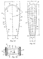
- Fig. 3B there is shown an end view from posterior end 28 of implant 20.
- Lateral surfaces 30 and 36 are substantially concave and they extend from top surface 22 to bottom surface 24.
- the radius of curvature for the concave surfaces is illustrated as R5.
- R5 is approximately 7.5 millimeters.
- Posterior end 28 has a width W3 at its midline 38.
- lateral concave surfaces 30 and 36 are formed at an angle A1 with respect to longitudinal axis L1. In a preferred aspect, angle A1 is approximately four and one-quarter degrees (4.25°). As illustrated in Fig.
- the width of the material forming the implant at midline 38 increases linearly from width W3 at posterior end 28 substantially greater width at anterior end 26.
- lateral surfaces 30 and 36 have a concave shape extending from top surface 22 to bottom surface 24 and project at an angle A1 with respect to longitudinal axis L1 as they extend from posterior end 28 to anterior end 26.
- This geometrical configuration provides the central portion of the implant with a tapering geometry of increasing thickness extending from posterior end 28 to anterior end 26.
- Fig. 3C illustrates a top view of implant 20 in accordance with another aspect of the present invention.
- the convex lateral edges 21 and 23 of top surface 22 are defined by radius R6 in a mirror image fashion about the longitudinal axis L1.
- the arc center point of radius R6 defining lateral edge 21 is not aligned with midpoint M of implant 20.
- arc center of radius R6 is located towards the anterior end 26 of the device and has radius length of approximately 150 millimeters.
- the arc center point of R6 is located 21.7 millimeters from posterior end 28 along the longitudinal axis L1 and 146.2 millimeters from longitudinal axis L1.
- the convex lateral edges 21 and 23 of top surface 22 defined by a center point offset from the device midpoint M define a device that increases from width W1 at posterior end 28 to width W2 at anterior end 26 in a non-linear fashion.
- W1 is approximately 4.5 millimeters and W2 is approximately 7.5 millimeters.
- the formation and shape of the convex lateral edges of bottom surface 24 are substantially identical to the convex lateral edges 21 and 23.
- anterior end 26 has a rounded insertion end set at an angle of approximately forty-five degrees (45°) from longitudinal axis L1 between top surface 22 and bottom surface 24. Additionally, the insertion end is rounded with the radius R4. In a preferred aspect, radius R4 is approximately 6.8 millimeters.
- FIG. 4A through 4C there is shown an alternative embodiment in accordance with another aspect of the present invention.
- Spacing implant 20' is shown with features substantially identical to implant 20 of Figs. 3A through 3C .
- the features of implant 20' are substantially identical to the features of implant 20.
- Implant 20' has a radius R1' of approximately 75 millimeters.
- the center point C' of radius R1' differs from the center point C of radius R1 (see Figs. 5 and 6 ). While still located towards the anterior portion of the device, direct center point C' is located closer to the midpoint M of implant 20'.
- the arc center point C' of R1' is located approximately 14.9 millimeters from posterior end 28 along longitudinal axis L1 and approximately 68 millimeters from longitudinal axis L1.
- the resulting height changes are that D1' is approximately 14 millimeters and D2' is approximately 11 millimeters.
- the resulting change in the center point for the radius R1' creates an implant that provides six degrees (6°) angulation between top surface 22 and bottom surface 24 as the device extends from anterior end 26 to posterior end 28.
- vertebrae V1 and V2 are space by implant 20' at an angle A3.
- angle A3 is approximately six degrees (6°).
- radius of curvature of concave lateral surfaces 36' is modified with a radius of curvature of R5'.
- R5' is approximately 5.2 millimeters with a center point extending with a substantial alignment with a longitudinal axis L1 of the device.
- concave lateral surfaces extend to an angle A1 with respect to longitudinal axis L1.
- a spacer may be configured with other dimensions suitable for interbody spacers at various levels of the spine for a variety of patient populations. For example, in an average patient population the anterior height of the device may range from 4 millimeters to 18 millimeters. Similarly, the posterior height of the device may range from 2 millimeters to 16 millimeters.
- the longitudinal offset of the center point defining the are of the top and bottom surfaces may be adjusted to create lordotic angulations ranging from 0° to 20°.
- a radius of 75 millimeters has been shown for the purpose of illustrating the convex arc of the top and bottom surfaces, alternative radii lengths ranging from 90 millimeters to 30 millimeters may be used. It is anticipated that such radii may approximate a wide range of spinal anatomies.
- Insertion tool 210 includes an inner shaft 212 slidably disposed within an outer tube 213.
- Inner shaft 212 includes a pair of opposing branches 218 and 220 spaced apart by gap 222.
- thumb wheel 214 may be rotated with respect to outer tube 213 to draw inner shaft 212 proximally thereby urging opposing branches 218 and 220 toward each other.
- Branch 218 has a substantially flat outer surface 224 that extends along much of the length of implant 250.
- Branch 218 terminates in a tapered tip 219.
- Branch 220 has a substantially flat outer surface 226 and terminates in a tapered tip 221.
- gripping branches 218 and 220 are substantially coterminous with the front end of implant 250.
- the gripping branches extend along lateral surfaces of the implant from the posterior end to immediately adjacent the anterior end 252 of the implant.
- gripping branch 218 has an inner gripping surface 230 having a convex surface substantially mating with the concave lateral surface of the implant.
- gripping branch 220 has a gripping surface 228 having a convex surface substantially mating with the concave lateral surface of the implant.
- each gripping branch 218 and 220 includes a shoulder 234 and 236, respectively, adapted to abut the posterior end of the implant to transmit impaction force during insertion.
- the maximum width of the gripping branches is substantially equal to or less than the maximum width of the implant 250.
- the surgical access necessary to implant the spacer 250 is solely a function of the size of the implant since the inserter is no larger in width or height than the implant itself.
- Figs. 11 through 13 illustrate a pair of implants 320 and 322 formed according to the present invention surgically implanted in a disc space between two adjacent vertebrae V1 and V2.
- Implants 320 and 322 may be impacted directly into the disc space with the upper and lower bone engaging surfaces positioned for immediate engagement with vertebrae V1 and V2.
- one or both implants may be inserted into the disc space with the bone engaging surfaces positioned laterally and rotated into the spacing position after insertion into the disc space.
- the smooth, rounded features of the implants according to the present invention may limit the potential to snag or abrade soft tissue, including neurological structures, during the insertion procedure.
- the blunt shape of the anterior end of the implant prevents damage to the anterior annulus A in the event that the implant is advanced too far anteriorly during implantation.
- graft material G may positioned around the lateral aspects of each implant 320 and 322 to completely fill the disc space annulus with graft material between and outside the spacers.
- the concave lateral surfaces of each implant maximize the amount of graft material G that may be place in the disc space. Additionally, while the narrow central portion of the implant maximizes graft material, the upper and lower bone engaging surfaces provide substantially greater surface area for engaging the endplates of vertebrae V1 and V2.
- a tool 340 may be used to advance bone graft into the disc space. Tool 340 may be guided off the concave lateral surfaces of the implants.
- Fixation implants 350 and 360 may be provided outside the disc space to provide further stabilization if slight adjustments to the angle of the lordosis between vertebrae V1 and V2 is desired, a distraction or compression tool may be applied to implants 350 and 360 move the vertebrae across the convex upper or lower surface of the implants 320 and 322 to modify the angulation between V 1 and V2.
- a spacer for positioning between adjacent vertebrae comprising: a central body portion having a front end, a rear end and a longitudinal axis extending between said front end and said rear end, a top surface extending along said longitudinal axis adapted for placement against a vertebra and an opposing bottom surface extending along said longitudinal axis configured for placement against a vertebra, and a first lateral surface having a concave shape between said top wall and said bottom wall, and an opposite second lateral surface having a concave shape between said top wall and said bottom wall, wherein said first lateral surface and said second lateral surface each extend longitudinally at a non-parallel angle with respect to said longitudinal axis.
- said lateral surface and said medial surface extend at an angle greater than three degrees with respect to each other.
- said front end has a first width transverse to said longitudinal axis and said rear end has a second width transverse to said longitudinal axis, said first width greater than said second width.
- said top surface further includes a first convex surface extending between said front end and said rear end
- said bottom surface further includes a second convex surface extending between said front end and said rear end.
- said body has a midpoint equidistant from said front and said rear end, said first convex surface defined by an arc extending from a center point, wherein said center point is offset from said midpoint.
- said center point is closer to said front end than said rear end.
- said top surface and said bottom surface each include a series of projections extending transverse to said longitudinal axis.
- said projections have a peak with a radius greater than 0.2 mm.
- said body is formed of radiolucent material.
- said body is formed of PEEK.
- the spacer according to the ninth further embodiment further includes at least one radiopaque marker having an exterior surface coplanar with at least a portion of said top surface.
- said body is formed at least in part of bone.
- a spacer for positioning between adjacent vertebrae comprising a body having an anterior portion and an opposite posterior portion disposed along a longitudinal axis, the body having a medial side and a lateral side and a width extending between said medial side and said lateral side; said anterior portion having a first width and the posterior portion having a second width, wherein the first width is greater than the second width.
- said medial side and said lateral side extend at a non-parallel angle with respect to said longitudinal axis.
- said non-parallel angle is greater than 1 degree with respect to said longitudinal axis.
- said medial side extends at an angle greater than 4 degrees with respect to said lateral side.
- said lateral side wall has a convex curvature and said medial side wall has a convex curvature.
- the body has a center point along said longitudinal axis and said convex curvature of said lateral side wall has an arc center point disposed anteriorly of said body center point.
- said convex curvature of said medial side wall has an arc center point disposed anteriorly of said body center point.
- an interbody implant for placement in the disc space between adjacent vertebrae, comprising a body having a front end and a back end, a longitudinal axis extending between said front end and said back end, and a midpoint disposed along said longitudinal axis equidistant from said front end and said back end; a top convex surface defined as a portion of a first arc having a first radius extending from a first center point, wherein said first center point is offset with respect to said midpoint; and a bottom convex surface defined as a portion of a second arc having a second radius extending from a second center point, wherein said center point is offset with respect to said midpoint.
- said first center point and said second center point are disposed closer to said front end than said back end.
- said implant has a height extending between said top convex surface and said bottom convex surface, said height greater adjacent said front end than said back end.
- said top convex surface and said bottom convex surface are disposed at an angular relationship between 0° and 20°.
- the angular relationship is between approximately 4° and 14°.
- the angular relationship is between approximately 6° and 12°.
- said first radius and said second radius have a length from approximately 30 millimeters to approximately 90 millimeters.
- said length is from approximately 50 millimeters to approximately 70 millimeters.
- said length is approximately 75 millimeters.
- said length is approximately 60 millimeters.
- a spacer for positioning between two adjacent vertebrae comprising a body having a front and a back end, a longitudinal axis extending between said front end and said back end, and a midpoint disposed along said longitudinal axis equidistant from said front end and said back end; and a top surface, a first side surface, and a first lateral edge disposed between said top surface and said side surface, said first lateral edge having a first convex shape defined as a first portion of an arc having a first radius extending from a first center point, wherein said center point is longitudinally offset with respect to said midpoint and is spaced from said longitudinal axis.
- said body in the spacer according to the thirtieth further embodiment, includes an opposite second side surface and a second lateral edge disposed between said top surface and said second side surface, and said second lateral edge having a convex shape defined as a portion of an arc having a radius extending from a center point, wherein said center point is longitudinally offset with respect to said midpoint and spaced from said longitudinal axis.
- said first center point and said second center point are disposed closer to said front end than said back end.
- said top surface includes a width extending between said first lateral edge and said second lateral edge, said width greater adjacent said front end than said back end.
- a combination comprising an implant having a body having a front end and a rear end with a longitudinal axis therebetween and an upper surface and an opposite lower surface adapted to engage vertebral body endplates spaced apart by a pair of opposing concave side surfaces, said implant having maximum width transverse to said longitudinal axis and a length from said front end to said rear end along said longitudinal axis; and an insertion tool having a gripping end with a tool width no greater than said maximum width, said gripping end having a first branch and an opposing second branch adapted to engage said pair of opposing concave surfaces.
- a method of making an interbody implant comprising providing an implant body formed at least in part from partially radiolucent material; embedding at least one substantially radiopaque marker in the implant body; shaping the implant body to a shape adapted for insertion between two vertebrae; and shaping the radiopaque marker to be substantially coterminous with a portion of the implant.
Landscapes
- Health & Medical Sciences (AREA)
- Engineering & Computer Science (AREA)
- Biomedical Technology (AREA)
- Orthopedic Medicine & Surgery (AREA)
- Neurology (AREA)
- Transplantation (AREA)
- Veterinary Medicine (AREA)
- General Health & Medical Sciences (AREA)
- Oral & Maxillofacial Surgery (AREA)
- Heart & Thoracic Surgery (AREA)
- Vascular Medicine (AREA)
- Life Sciences & Earth Sciences (AREA)
- Animal Behavior & Ethology (AREA)
- Cardiology (AREA)
- Public Health (AREA)
- Physical Education & Sports Medicine (AREA)
- Prostheses (AREA)
- Lining Or Joining Of Plastics Or The Like (AREA)
- Safety Valves (AREA)
- Massaging Devices (AREA)
Applications Claiming Priority (2)
| Application Number | Priority Date | Filing Date | Title |
|---|---|---|---|
| US10/404,262 US7326251B2 (en) | 2003-04-01 | 2003-04-01 | Interbody fusion device |
| EP04759680A EP1617793B1 (de) | 2003-04-01 | 2004-03-19 | Zwischenwirbel-fusionsvorrichtung |
Related Parent Applications (2)
| Application Number | Title | Priority Date | Filing Date |
|---|---|---|---|
| EP04759680.4 Division | 2004-03-19 | ||
| EP04759680A Division EP1617793B1 (de) | 2003-04-01 | 2004-03-19 | Zwischenwirbel-fusionsvorrichtung |
Publications (2)
| Publication Number | Publication Date |
|---|---|
| EP2111823A1 true EP2111823A1 (de) | 2009-10-28 |
| EP2111823B1 EP2111823B1 (de) | 2010-08-25 |
Family
ID=33096904
Family Applications (2)
| Application Number | Title | Priority Date | Filing Date |
|---|---|---|---|
| EP04759680A Expired - Lifetime EP1617793B1 (de) | 2003-04-01 | 2004-03-19 | Zwischenwirbel-fusionsvorrichtung |
| EP09165016A Expired - Lifetime EP2111823B1 (de) | 2003-04-01 | 2004-03-19 | Zwischenwirbelfusionsvorrichtung |
Family Applications Before (1)
| Application Number | Title | Priority Date | Filing Date |
|---|---|---|---|
| EP04759680A Expired - Lifetime EP1617793B1 (de) | 2003-04-01 | 2004-03-19 | Zwischenwirbel-fusionsvorrichtung |
Country Status (9)
| Country | Link |
|---|---|
| US (4) | US7326251B2 (de) |
| EP (2) | EP1617793B1 (de) |
| AT (2) | ATE478631T1 (de) |
| AU (2) | AU2004231525B2 (de) |
| CA (1) | CA2522951A1 (de) |
| DE (2) | DE602004028883D1 (de) |
| ES (1) | ES2330747T3 (de) |
| PL (1) | PL1617793T3 (de) |
| WO (1) | WO2004093752A2 (de) |
Families Citing this family (89)
| Publication number | Priority date | Publication date | Assignee | Title |
|---|---|---|---|---|
| US6206922B1 (en) * | 1995-03-27 | 2001-03-27 | Sdgi Holdings, Inc. | Methods and instruments for interbody fusion |
| US8535378B2 (en) * | 2004-05-10 | 2013-09-17 | Roger P. Jackson | Vertebral interbody spacer |
| JP4164315B2 (ja) * | 2002-08-20 | 2008-10-15 | 昭和医科工業株式会社 | 椎間スペーサー |
| AR036713A1 (es) * | 2002-10-02 | 2004-09-29 | Carrasco Mauricio Rodolfo | Implante para corregir una deformidad de la columna vertebral. |
| US7326251B2 (en) * | 2003-04-01 | 2008-02-05 | Sdgi Holdings, Inc. | Interbody fusion device |
| US7918891B1 (en) * | 2004-03-29 | 2011-04-05 | Nuvasive Inc. | Systems and methods for spinal fusion |
| US7794500B2 (en) * | 2004-10-27 | 2010-09-14 | Felix Brent A | Surgical implant |
| US8597360B2 (en) | 2004-11-03 | 2013-12-03 | Neuropro Technologies, Inc. | Bone fusion device |
| US20090210059A1 (en) | 2005-04-06 | 2009-08-20 | Mccombe Peter Francis | Vertebral Disc Prosthesis |
| US8623088B1 (en) | 2005-07-15 | 2014-01-07 | Nuvasive, Inc. | Spinal fusion implant and related methods |
| US8236058B2 (en) | 2005-09-27 | 2012-08-07 | Fabian Henry F | Spine surgery method and implant |
| US9271843B2 (en) | 2005-09-27 | 2016-03-01 | Henry F. Fabian | Spine surgery method and implant |
| AU2006308801B2 (en) * | 2005-11-04 | 2012-03-22 | Nuvasive, Inc. | A method of reducing loading failure for a prosthetic component |
| CA2628236A1 (en) * | 2005-11-04 | 2007-05-10 | Peter Mccombe | A method of reducing loading failure for a prosthetic component |
| US8062372B2 (en) * | 2005-12-29 | 2011-11-22 | Industrial Technology Research Institute | Spinal fusion device |
| US7892239B2 (en) * | 2006-03-22 | 2011-02-22 | Beacon Biomedical, Llc | Pivotable interbody spacer system and method |
| US9345587B2 (en) | 2006-03-22 | 2016-05-24 | Beacon Biomedical, Llc | Pivotal lateral cage and method of insertion |
| EP1998720B1 (de) * | 2006-03-22 | 2021-05-12 | Alphaspine, Inc. | Drehbares zwischenwirbelabstandsstück |
| US7871441B2 (en) * | 2006-04-28 | 2011-01-18 | Concept Matrix, Llc | Cervical fixation device |
| US8002837B2 (en) | 2006-05-19 | 2011-08-23 | Pioneer Surgical Technology | Spinal stabilization device and methods |
| WO2008002992A1 (en) * | 2006-06-27 | 2008-01-03 | Smith & Nephew, Inc. | Radiolucent external fixation element with radio-opaque alignment structures |
| USD741488S1 (en) | 2006-07-17 | 2015-10-20 | Nuvasive, Inc. | Spinal fusion implant |
| US20080082172A1 (en) * | 2006-09-29 | 2008-04-03 | Jackson Roger P | Interspinous process spacer |
| US8097037B2 (en) * | 2006-12-20 | 2012-01-17 | Depuy Spine, Inc. | Methods and devices for correcting spinal deformities |
| USD566842S1 (en) | 2007-02-19 | 2008-04-15 | Zimmer Spine, Inc. | Spinal implant |
| US8673005B1 (en) | 2007-03-07 | 2014-03-18 | Nuvasive, Inc. | System and methods for spinal fusion |
| US7822465B2 (en) * | 2007-04-25 | 2010-10-26 | Warsaw Orthopedic, Inc. | Device and method for image-based device performance measurement |
| US9101491B2 (en) * | 2007-12-28 | 2015-08-11 | Nuvasive, Inc. | Spinal surgical implant and related methods |
| USD612500S1 (en) * | 2008-01-29 | 2010-03-23 | Karl Storz Gmbh & Co. Kg | Medical implant or medical prosthesis |
| US8267939B2 (en) | 2008-02-28 | 2012-09-18 | Stryker Spine | Tool for implanting expandable intervertebral implant |
| US20090222011A1 (en) * | 2008-02-28 | 2009-09-03 | Warsaw Orthopedic, Inc. | Targeting surgical instrument for use in spinal disc replacement and methods for use in spinal disc replacement |
| US8083796B1 (en) | 2008-02-29 | 2011-12-27 | Nuvasive, Inc. | Implants and methods for spinal fusion |
| US20090270873A1 (en) | 2008-04-24 | 2009-10-29 | Fabian Henry F | Spine surgery method and inserter |
| USD619255S1 (en) * | 2008-07-26 | 2010-07-06 | Ulrich Gmbh & Co. Kg | Spinal implant |
| US9408649B2 (en) * | 2008-09-11 | 2016-08-09 | Innovasis, Inc. | Radiolucent screw with radiopaque marker |
| US8147554B2 (en) * | 2008-10-13 | 2012-04-03 | Globus Medical, Inc. | Intervertebral spacer |
| USD621509S1 (en) | 2008-10-15 | 2010-08-10 | Nuvasive, Inc. | Intervertebral implant |
| USD620112S1 (en) * | 2008-12-02 | 2010-07-20 | Eminent Spine Llc | Interbody fusion device implant |
| US8080062B2 (en) * | 2008-12-02 | 2011-12-20 | Warsaw Orthopedic, Inc. | Intervertebral implant with fixation mechanism |
| USD754346S1 (en) | 2009-03-02 | 2016-04-19 | Nuvasive, Inc. | Spinal fusion implant |
| USD627467S1 (en) * | 2009-06-26 | 2010-11-16 | Pannu Yashdip S | Spinal insert |
| USD620116S1 (en) * | 2009-06-26 | 2010-07-20 | Pannu Yashdip S | Spinal insert |
| USD619719S1 (en) * | 2009-06-26 | 2010-07-13 | Pannu Yashdip S | Spinal insert |
| USD620114S1 (en) * | 2009-06-26 | 2010-07-20 | Pannu Yashdip S | Spinal insert |
| USD620115S1 (en) * | 2009-06-26 | 2010-07-20 | Pannu Yashdip S | Spinal insert |
| US9433439B2 (en) * | 2009-09-10 | 2016-09-06 | Innovasis, Inc. | Radiolucent stabilizing rod with radiopaque marker |
| USD731063S1 (en) | 2009-10-13 | 2015-06-02 | Nuvasive, Inc. | Spinal fusion implant |
| US8801712B2 (en) * | 2010-03-08 | 2014-08-12 | Innovasis, Inc. | Radiolucent bone plate with radiopaque marker |
| CN102892387B (zh) | 2010-03-16 | 2016-03-16 | 品尼高脊柱集团有限责任公司 | 椎间植入物以及移植物输送系统和方法 |
| US12472069B2 (en) * | 2010-07-27 | 2025-11-18 | Tenon Medical, Inc. | Methods for sacroiliac joint stabilization |
| US12465491B2 (en) * | 2010-07-27 | 2025-11-11 | Tenon Medical, Inc. | Methods for sacroiliac joint stabilization |
| US12409039B2 (en) * | 2010-07-27 | 2025-09-09 | Tenon Medical, Inc. | Systems for sacroiliac joint stabilization |
| US20120191193A1 (en) * | 2011-01-26 | 2012-07-26 | Warsaw Orthopedic | Interbody implant system and methods of use |
| US9095445B2 (en) | 2011-07-14 | 2015-08-04 | Warsaw Orthopedic, Inc. | Vertebral interbody spacer |
| US9358123B2 (en) | 2011-08-09 | 2016-06-07 | Neuropro Spinal Jaxx, Inc. | Bone fusion device, apparatus and method |
| WO2013023096A1 (en) | 2011-08-09 | 2013-02-14 | Neuropro Technologies, Inc. | Bone fusion device, system and method |
| JP6047571B2 (ja) | 2011-08-16 | 2016-12-21 | ストライカー・スピン | 拡張可能な移植片 |
| US9132021B2 (en) | 2011-10-07 | 2015-09-15 | Pioneer Surgical Technology, Inc. | Intervertebral implant |
| US9198765B1 (en) | 2011-10-31 | 2015-12-01 | Nuvasive, Inc. | Expandable spinal fusion implants and related methods |
| US9380932B1 (en) | 2011-11-02 | 2016-07-05 | Pinnacle Spine Group, Llc | Retractor devices for minimally invasive access to the spine |
| USD675320S1 (en) | 2011-11-03 | 2013-01-29 | Nuvasive, Inc. | Intervertebral implant |
| US9532883B2 (en) | 2012-04-13 | 2017-01-03 | Neuropro Technologies, Inc. | Bone fusion device |
| US8814912B2 (en) | 2012-07-27 | 2014-08-26 | Zimmer Spine, Inc. | Bone stabilization member with bone screw retention mechanism |
| US10342675B2 (en) | 2013-03-11 | 2019-07-09 | Stryker European Holdings I, Llc | Expandable implant |
| WO2014159739A1 (en) | 2013-03-14 | 2014-10-02 | Pinnacle Spine Group, Llc | Interbody implants and graft delivery systems |
| US10098757B2 (en) | 2013-03-15 | 2018-10-16 | Neuropro Technologies Inc. | Bodiless bone fusion device, apparatus and method |
| FR3006170B1 (fr) * | 2013-05-31 | 2015-06-26 | Osd Orthopaedic & Spine Dev | Prothese intersomatique produisant un reglage de lordose individualise |
| USD745159S1 (en) | 2013-10-10 | 2015-12-08 | Nuvasive, Inc. | Intervertebral implant |
| US10016281B2 (en) | 2014-08-08 | 2018-07-10 | Howard Yeon | Spinal intervertebral implant |
| USD858769S1 (en) | 2014-11-20 | 2019-09-03 | Nuvasive, Inc. | Intervertebral implant |
| US10555818B2 (en) | 2015-04-23 | 2020-02-11 | Institute for Musculoskeletal Science and Education, Ltd. | Spinal fusion implant for oblique insertion |
| US10292834B2 (en) | 2016-06-27 | 2019-05-21 | Globus Medical, Inc. | Intervertebral spacer with chamfered edges |
| US10292825B2 (en) | 2016-06-27 | 2019-05-21 | Globus Medical, Inc. | Intervertebral spacer with chamfered edges |
| JP6813968B2 (ja) * | 2016-07-01 | 2021-01-13 | 日本特殊陶業株式会社 | 椎体スペーサ |
| US11058551B2 (en) | 2016-12-16 | 2021-07-13 | Advance Research System, Llc | Interbody implant with concave profiled nose |
| US10111760B2 (en) | 2017-01-18 | 2018-10-30 | Neuropro Technologies, Inc. | Bone fusion system, device and method including a measuring mechanism |
| US10973657B2 (en) | 2017-01-18 | 2021-04-13 | Neuropro Technologies, Inc. | Bone fusion surgical system and method |
| US10729560B2 (en) | 2017-01-18 | 2020-08-04 | Neuropro Technologies, Inc. | Bone fusion system, device and method including an insertion instrument |
| US10213321B2 (en) | 2017-01-18 | 2019-02-26 | Neuropro Technologies, Inc. | Bone fusion system, device and method including delivery apparatus |
| USD879295S1 (en) | 2017-02-13 | 2020-03-24 | Advance Research System, Llc | Spinal fusion cage |
| EP3678602A4 (de) | 2017-09-08 | 2021-10-06 | Pioneer Surgical Technology, Inc. | Bandscheibenimplantate, instrumente und verfahren |
| DE102017008592A1 (de) * | 2017-09-13 | 2019-03-14 | Joimax Gmbh | Zwischenwirbel-lmplantat |
| USD907771S1 (en) | 2017-10-09 | 2021-01-12 | Pioneer Surgical Technology, Inc. | Intervertebral implant |
| US11737888B1 (en) | 2019-09-19 | 2023-08-29 | Advance Research System, Llc | Spinal fusion implant system and method |
| US11883303B2 (en) | 2019-12-30 | 2024-01-30 | Vertebration, Inc. | Spine surgery method and instrumentation |
| USD948050S1 (en) | 2020-02-12 | 2022-04-05 | Warsaw Orthopedic, Inc. | Spinal implant |
| US11357645B2 (en) | 2020-04-17 | 2022-06-14 | Warsaw Orthopedic, Inc. | Implant with graded radiopacity calibration feature |
| USD1021098S1 (en) * | 2021-08-31 | 2024-04-02 | Shukla Medical | Surgical implant extractor jaw |
| CN117017590B (zh) * | 2023-10-09 | 2024-01-23 | 北京爱康宜诚医疗器材有限公司 | 人工椎体假体组件 |
Citations (4)
| Publication number | Priority date | Publication date | Assignee | Title |
|---|---|---|---|---|
| DE20012236U1 (de) * | 2000-07-14 | 2000-10-12 | Corin Spinal Systems Ltd., Cirencester, Gloucestershire | Implantat zur operativen Wirbelsäulenversteifung |
| WO2000074608A1 (en) * | 1999-06-08 | 2000-12-14 | Osteotech, Inc. | Ramp-shaped intervertebral implant |
| US20020068973A1 (en) * | 2000-12-04 | 2002-06-06 | Jackson Roger P. | Threaded interbody device |
| US6500206B1 (en) * | 2000-09-15 | 2002-12-31 | Donald W. Bryan | Instruments for inserting spinal vertebral implant |
Family Cites Families (35)
| Publication number | Priority date | Publication date | Assignee | Title |
|---|---|---|---|---|
| US2677369A (en) * | 1952-03-26 | 1954-05-04 | Fred L Knowles | Apparatus for treatment of the spinal column |
| DE8912648U1 (de) * | 1989-10-23 | 1990-11-22 | Mecron Medizinische Produkte Gmbh, 1000 Berlin | Wirbelkörperimplantat |
| JP3007903B2 (ja) * | 1991-03-29 | 2000-02-14 | 京セラ株式会社 | 人工椎間板 |
| US5425772A (en) | 1993-09-20 | 1995-06-20 | Brantigan; John W. | Prosthetic implant for intervertebral spinal fusion |
| BE1007549A3 (nl) | 1993-09-21 | 1995-08-01 | Beckers Louis Francois Charles | Implantaat. |
| US5443514A (en) | 1993-10-01 | 1995-08-22 | Acromed Corporation | Method for using spinal implants |
| WO1995031947A1 (en) * | 1994-05-23 | 1995-11-30 | Spine-Tech, Inc. | Intervertebral fusion implant |
| US6206922B1 (en) * | 1995-03-27 | 2001-03-27 | Sdgi Holdings, Inc. | Methods and instruments for interbody fusion |
| FR2753368B1 (fr) * | 1996-09-13 | 1999-01-08 | Chauvin Jean Luc | Cage d'osteosynthese expansive |
| US5904719A (en) * | 1997-07-24 | 1999-05-18 | Techsys Medical, Llc | Interbody fusion device having partial circular section cross-sectional segments |
| US5888226A (en) * | 1997-11-12 | 1999-03-30 | Rogozinski; Chaim | Intervertebral prosthetic disc |
| FR2772594B1 (fr) * | 1997-12-19 | 2000-05-05 | Henry Graf | Prothese discale partielle posterieure |
| DE29901612U1 (de) * | 1998-01-23 | 1999-04-08 | Aesculap AG & Co. KG, 78532 Tuttlingen | Zwischenwirbelimplantat |
| US6224631B1 (en) * | 1998-03-20 | 2001-05-01 | Sulzer Spine-Tech Inc. | Intervertebral implant with reduced contact area and method |
| US6290724B1 (en) * | 1998-05-27 | 2001-09-18 | Nuvasive, Inc. | Methods for separating and stabilizing adjacent vertebrae |
| US6099531A (en) * | 1998-08-20 | 2000-08-08 | Bonutti; Peter M. | Changing relationship between bones |
| US6174311B1 (en) * | 1998-10-28 | 2001-01-16 | Sdgi Holdings, Inc. | Interbody fusion grafts and instrumentation |
| CA2361068A1 (en) * | 1999-02-04 | 2000-08-10 | Sdgi Holdings, Inc. | Improved interbody fusion device with anti-rotation features |
| US6245108B1 (en) * | 1999-02-25 | 2001-06-12 | Spineco | Spinal fusion implant |
| CA2363562C (en) * | 1999-05-05 | 2010-08-03 | Gary Karlin Michelson | Nested interbody spinal fusion implants |
| WO2000066045A1 (en) * | 1999-05-05 | 2000-11-09 | Michelson Gary K | Spinal fusion implants with opposed locking screws |
| WO2001013807A2 (en) * | 1999-08-26 | 2001-03-01 | Sdgi Holdings, Inc. | Devices and methods for implanting fusion cages |
| US6648915B2 (en) * | 1999-12-23 | 2003-11-18 | John A. Sazy | Intervertebral cage and method of use |
| US20010032017A1 (en) * | 1999-12-30 | 2001-10-18 | Alfaro Arthur A. | Intervertebral implants |
| US7195643B2 (en) * | 2003-08-29 | 2007-03-27 | Jackson Roger P | Convex spinal fusion interbody spacer |
| US20060167548A1 (en) * | 2000-08-23 | 2006-07-27 | Jackson Roger P | Non-linear spinal fusion interbody spacer |
| US20020029082A1 (en) * | 2000-08-29 | 2002-03-07 | Muhanna Nabil L. | Vertebral spacer and method of use |
| JP2004533272A (ja) * | 2000-10-24 | 2004-11-04 | ハウメディカ・オステオニクス・コーポレイション | 癒合用インプラント装置 |
| AU2002213340A1 (en) * | 2000-10-24 | 2002-05-06 | Howmedica Osteonics Corp. | Threaded, barrel-shaped apparatus for fusing adjacent bone structure |
| US6719794B2 (en) * | 2001-05-03 | 2004-04-13 | Synthes (U.S.A.) | Intervertebral implant for transforaminal posterior lumbar interbody fusion procedure |
| JP2005516669A (ja) * | 2002-02-07 | 2005-06-09 | イービーアイ,エル.ピー. | 前脊椎インプラント |
| JP4164315B2 (ja) * | 2002-08-20 | 2008-10-15 | 昭和医科工業株式会社 | 椎間スペーサー |
| US20040127922A1 (en) * | 2002-12-30 | 2004-07-01 | Cull Laurence J. | Microkeratome cutting blade assembly |
| US7326251B2 (en) * | 2003-04-01 | 2008-02-05 | Sdgi Holdings, Inc. | Interbody fusion device |
| USD503801S1 (en) * | 2004-04-05 | 2005-04-05 | Roger P. Jackson | Interbody spacer for spinal implantation |
-
2003
- 2003-04-01 US US10/404,262 patent/US7326251B2/en not_active Expired - Lifetime
-
2004
- 2004-03-19 WO PCT/US2004/008414 patent/WO2004093752A2/en not_active Ceased
- 2004-03-19 AT AT09165016T patent/ATE478631T1/de not_active IP Right Cessation
- 2004-03-19 AU AU2004231525A patent/AU2004231525B2/en not_active Expired
- 2004-03-19 CA CA002522951A patent/CA2522951A1/en not_active Abandoned
- 2004-03-19 PL PL04759680T patent/PL1617793T3/pl unknown
- 2004-03-19 DE DE602004028883T patent/DE602004028883D1/de not_active Expired - Lifetime
- 2004-03-19 AT AT04759680T patent/ATE442824T1/de not_active IP Right Cessation
- 2004-03-19 ES ES04759680T patent/ES2330747T3/es not_active Expired - Lifetime
- 2004-03-19 EP EP04759680A patent/EP1617793B1/de not_active Expired - Lifetime
- 2004-03-19 EP EP09165016A patent/EP2111823B1/de not_active Expired - Lifetime
- 2004-03-19 DE DE602004023187T patent/DE602004023187D1/de not_active Expired - Lifetime
-
2008
- 2008-01-28 US US12/021,107 patent/US7951203B2/en not_active Expired - Fee Related
-
2010
- 2010-03-09 AU AU2010200881A patent/AU2010200881B2/en not_active Ceased
-
2011
- 2011-04-08 US US13/083,296 patent/US8591589B2/en not_active Expired - Fee Related
-
2013
- 2013-09-26 US US14/037,730 patent/US20140031941A1/en not_active Abandoned
Patent Citations (4)
| Publication number | Priority date | Publication date | Assignee | Title |
|---|---|---|---|---|
| WO2000074608A1 (en) * | 1999-06-08 | 2000-12-14 | Osteotech, Inc. | Ramp-shaped intervertebral implant |
| DE20012236U1 (de) * | 2000-07-14 | 2000-10-12 | Corin Spinal Systems Ltd., Cirencester, Gloucestershire | Implantat zur operativen Wirbelsäulenversteifung |
| US6500206B1 (en) * | 2000-09-15 | 2002-12-31 | Donald W. Bryan | Instruments for inserting spinal vertebral implant |
| US20020068973A1 (en) * | 2000-12-04 | 2002-06-06 | Jackson Roger P. | Threaded interbody device |
Also Published As
| Publication number | Publication date |
|---|---|
| AU2004231525A1 (en) | 2004-11-04 |
| PL1617793T3 (pl) | 2010-02-26 |
| US20140031941A1 (en) | 2014-01-30 |
| US8591589B2 (en) | 2013-11-26 |
| US20040199251A1 (en) | 2004-10-07 |
| US7951203B2 (en) | 2011-05-31 |
| AU2004231525B2 (en) | 2009-12-10 |
| US20110196496A1 (en) | 2011-08-11 |
| WO2004093752A2 (en) | 2004-11-04 |
| DE602004023187D1 (de) | 2009-10-29 |
| AU2010200881A1 (en) | 2010-04-01 |
| EP1617793B1 (de) | 2009-09-16 |
| AU2010200881B2 (en) | 2012-09-13 |
| EP2111823B1 (de) | 2010-08-25 |
| CA2522951A1 (en) | 2004-11-04 |
| WO2004093752A3 (en) | 2004-12-23 |
| EP1617793A2 (de) | 2006-01-25 |
| US20080119937A1 (en) | 2008-05-22 |
| ES2330747T3 (es) | 2009-12-15 |
| DE602004028883D1 (de) | 2010-10-07 |
| ATE442824T1 (de) | 2009-10-15 |
| US7326251B2 (en) | 2008-02-05 |
| ATE478631T1 (de) | 2010-09-15 |
Similar Documents
| Publication | Publication Date | Title |
|---|---|---|
| EP2111823B1 (de) | Zwischenwirbelfusionsvorrichtung | |
| US12144741B2 (en) | Intervertebral implant | |
| US20220273459A1 (en) | Method and spacer device for spanning a space formed upon removal of an intervertebral disc | |
| CN103648421B (zh) | 椎体间间隔物 | |
| US20060241760A1 (en) | Spinal implant | |
| WO2011094699A2 (en) | Lordotic interbody device with different sized rails | |
| AU2004211984A1 (en) | Device for fusing two bone segments |
Legal Events
| Date | Code | Title | Description |
|---|---|---|---|
| PUAI | Public reference made under article 153(3) epc to a published international application that has entered the european phase |
Free format text: ORIGINAL CODE: 0009012 |
|
| AC | Divisional application: reference to earlier application |
Ref document number: 1617793 Country of ref document: EP Kind code of ref document: P |
|
| AK | Designated contracting states |
Kind code of ref document: A1 Designated state(s): AT BE BG CH CY CZ DE DK EE ES FI FR GB GR HU IE IT LI LU MC NL PL PT RO SE SI SK TR |
|
| RIN1 | Information on inventor provided before grant (corrected) |
Inventor name: BARKER, THOMAS B. Inventor name: SEARS, WILLIAM Inventor name: POWERS, RUSSELL Inventor name: WARMBOLD, DAVID A. Inventor name: MCCOMBE, PETER |
|
| 17P | Request for examination filed |
Effective date: 20091119 |
|
| GRAP | Despatch of communication of intention to grant a patent |
Free format text: ORIGINAL CODE: EPIDOSNIGR1 |
|
| GRAS | Grant fee paid |
Free format text: ORIGINAL CODE: EPIDOSNIGR3 |
|
| GRAA | (expected) grant |
Free format text: ORIGINAL CODE: 0009210 |
|
| AC | Divisional application: reference to earlier application |
Ref document number: 1617793 Country of ref document: EP Kind code of ref document: P |
|
| AK | Designated contracting states |
Kind code of ref document: B1 Designated state(s): AT BE BG CH CY CZ DE DK EE ES FI FR GB GR HU IE IT LI LU MC NL PL PT RO SE SI SK TR |
|
| REG | Reference to a national code |
Ref country code: GB Ref legal event code: FG4D |
|
| REG | Reference to a national code |
Ref country code: CH Ref legal event code: EP |
|
| REG | Reference to a national code |
Ref country code: IE Ref legal event code: FG4D |
|
| REF | Corresponds to: |
Ref document number: 602004028883 Country of ref document: DE Date of ref document: 20101007 Kind code of ref document: P |
|
| REG | Reference to a national code |
Ref country code: CH Ref legal event code: NV Representative=s name: PATENTANWAELTE SCHAAD, BALASS, MENZL & PARTNER AG |
|
| REG | Reference to a national code |
Ref country code: NL Ref legal event code: VDEP Effective date: 20100825 |
|
| PG25 | Lapsed in a contracting state [announced via postgrant information from national office to epo] |
Ref country code: AT Free format text: LAPSE BECAUSE OF FAILURE TO SUBMIT A TRANSLATION OF THE DESCRIPTION OR TO PAY THE FEE WITHIN THE PRESCRIBED TIME-LIMIT Effective date: 20100825 Ref country code: FI Free format text: LAPSE BECAUSE OF FAILURE TO SUBMIT A TRANSLATION OF THE DESCRIPTION OR TO PAY THE FEE WITHIN THE PRESCRIBED TIME-LIMIT Effective date: 20100825 |
|
| PG25 | Lapsed in a contracting state [announced via postgrant information from national office to epo] |
Ref country code: BG Free format text: LAPSE BECAUSE OF FAILURE TO SUBMIT A TRANSLATION OF THE DESCRIPTION OR TO PAY THE FEE WITHIN THE PRESCRIBED TIME-LIMIT Effective date: 20101125 Ref country code: SI Free format text: LAPSE BECAUSE OF FAILURE TO SUBMIT A TRANSLATION OF THE DESCRIPTION OR TO PAY THE FEE WITHIN THE PRESCRIBED TIME-LIMIT Effective date: 20100825 Ref country code: PT Free format text: LAPSE BECAUSE OF FAILURE TO SUBMIT A TRANSLATION OF THE DESCRIPTION OR TO PAY THE FEE WITHIN THE PRESCRIBED TIME-LIMIT Effective date: 20101227 Ref country code: PL Free format text: LAPSE BECAUSE OF FAILURE TO SUBMIT A TRANSLATION OF THE DESCRIPTION OR TO PAY THE FEE WITHIN THE PRESCRIBED TIME-LIMIT Effective date: 20100825 Ref country code: CY Free format text: LAPSE BECAUSE OF FAILURE TO SUBMIT A TRANSLATION OF THE DESCRIPTION OR TO PAY THE FEE WITHIN THE PRESCRIBED TIME-LIMIT Effective date: 20100825 |
|
| PG25 | Lapsed in a contracting state [announced via postgrant information from national office to epo] |
Ref country code: SE Free format text: LAPSE BECAUSE OF FAILURE TO SUBMIT A TRANSLATION OF THE DESCRIPTION OR TO PAY THE FEE WITHIN THE PRESCRIBED TIME-LIMIT Effective date: 20100825 Ref country code: GR Free format text: LAPSE BECAUSE OF FAILURE TO SUBMIT A TRANSLATION OF THE DESCRIPTION OR TO PAY THE FEE WITHIN THE PRESCRIBED TIME-LIMIT Effective date: 20101126 Ref country code: NL Free format text: LAPSE BECAUSE OF FAILURE TO SUBMIT A TRANSLATION OF THE DESCRIPTION OR TO PAY THE FEE WITHIN THE PRESCRIBED TIME-LIMIT Effective date: 20100825 Ref country code: BE Free format text: LAPSE BECAUSE OF FAILURE TO SUBMIT A TRANSLATION OF THE DESCRIPTION OR TO PAY THE FEE WITHIN THE PRESCRIBED TIME-LIMIT Effective date: 20100825 |
|
| PG25 | Lapsed in a contracting state [announced via postgrant information from national office to epo] |
Ref country code: DK Free format text: LAPSE BECAUSE OF FAILURE TO SUBMIT A TRANSLATION OF THE DESCRIPTION OR TO PAY THE FEE WITHIN THE PRESCRIBED TIME-LIMIT Effective date: 20100825 |
|
| PG25 | Lapsed in a contracting state [announced via postgrant information from national office to epo] |
Ref country code: CZ Free format text: LAPSE BECAUSE OF FAILURE TO SUBMIT A TRANSLATION OF THE DESCRIPTION OR TO PAY THE FEE WITHIN THE PRESCRIBED TIME-LIMIT Effective date: 20100825 Ref country code: EE Free format text: LAPSE BECAUSE OF FAILURE TO SUBMIT A TRANSLATION OF THE DESCRIPTION OR TO PAY THE FEE WITHIN THE PRESCRIBED TIME-LIMIT Effective date: 20100825 Ref country code: IT Free format text: LAPSE BECAUSE OF FAILURE TO SUBMIT A TRANSLATION OF THE DESCRIPTION OR TO PAY THE FEE WITHIN THE PRESCRIBED TIME-LIMIT Effective date: 20100825 Ref country code: SK Free format text: LAPSE BECAUSE OF FAILURE TO SUBMIT A TRANSLATION OF THE DESCRIPTION OR TO PAY THE FEE WITHIN THE PRESCRIBED TIME-LIMIT Effective date: 20100825 Ref country code: RO Free format text: LAPSE BECAUSE OF FAILURE TO SUBMIT A TRANSLATION OF THE DESCRIPTION OR TO PAY THE FEE WITHIN THE PRESCRIBED TIME-LIMIT Effective date: 20100825 |
|
| PG25 | Lapsed in a contracting state [announced via postgrant information from national office to epo] |
Ref country code: ES Free format text: LAPSE BECAUSE OF FAILURE TO SUBMIT A TRANSLATION OF THE DESCRIPTION OR TO PAY THE FEE WITHIN THE PRESCRIBED TIME-LIMIT Effective date: 20101206 |
|
| PLBE | No opposition filed within time limit |
Free format text: ORIGINAL CODE: 0009261 |
|
| STAA | Information on the status of an ep patent application or granted ep patent |
Free format text: STATUS: NO OPPOSITION FILED WITHIN TIME LIMIT |
|
| 26N | No opposition filed |
Effective date: 20110526 |
|
| REG | Reference to a national code |
Ref country code: DE Ref legal event code: R097 Ref document number: 602004028883 Country of ref document: DE Effective date: 20110526 |
|
| PG25 | Lapsed in a contracting state [announced via postgrant information from national office to epo] |
Ref country code: MC Free format text: LAPSE BECAUSE OF NON-PAYMENT OF DUE FEES Effective date: 20110331 |
|
| REG | Reference to a national code |
Ref country code: IE Ref legal event code: MM4A |
|
| PG25 | Lapsed in a contracting state [announced via postgrant information from national office to epo] |
Ref country code: IE Free format text: LAPSE BECAUSE OF NON-PAYMENT OF DUE FEES Effective date: 20110319 |
|
| PGFP | Annual fee paid to national office [announced via postgrant information from national office to epo] |
Ref country code: GB Payment date: 20130327 Year of fee payment: 10 |
|
| PG25 | Lapsed in a contracting state [announced via postgrant information from national office to epo] |
Ref country code: LU Free format text: LAPSE BECAUSE OF NON-PAYMENT OF DUE FEES Effective date: 20110319 |
|
| PG25 | Lapsed in a contracting state [announced via postgrant information from national office to epo] |
Ref country code: TR Free format text: LAPSE BECAUSE OF FAILURE TO SUBMIT A TRANSLATION OF THE DESCRIPTION OR TO PAY THE FEE WITHIN THE PRESCRIBED TIME-LIMIT Effective date: 20100825 |
|
| PG25 | Lapsed in a contracting state [announced via postgrant information from national office to epo] |
Ref country code: HU Free format text: LAPSE BECAUSE OF FAILURE TO SUBMIT A TRANSLATION OF THE DESCRIPTION OR TO PAY THE FEE WITHIN THE PRESCRIBED TIME-LIMIT Effective date: 20100825 |
|
| GBPC | Gb: european patent ceased through non-payment of renewal fee |
Effective date: 20140319 |
|
| PG25 | Lapsed in a contracting state [announced via postgrant information from national office to epo] |
Ref country code: GB Free format text: LAPSE BECAUSE OF NON-PAYMENT OF DUE FEES Effective date: 20140319 |
|
| REG | Reference to a national code |
Ref country code: FR Ref legal event code: PLFP Year of fee payment: 13 |
|
| PGFP | Annual fee paid to national office [announced via postgrant information from national office to epo] |
Ref country code: CH Payment date: 20160328 Year of fee payment: 13 |
|
| PGFP | Annual fee paid to national office [announced via postgrant information from national office to epo] |
Ref country code: FR Payment date: 20160328 Year of fee payment: 13 |
|
| PGFP | Annual fee paid to national office [announced via postgrant information from national office to epo] |
Ref country code: DE Payment date: 20160331 Year of fee payment: 13 |
|
| REG | Reference to a national code |
Ref country code: DE Ref legal event code: R119 Ref document number: 602004028883 Country of ref document: DE |
|
| REG | Reference to a national code |
Ref country code: CH Ref legal event code: PL |
|
| REG | Reference to a national code |
Ref country code: FR Ref legal event code: ST Effective date: 20171130 |
|
| PG25 | Lapsed in a contracting state [announced via postgrant information from national office to epo] |
Ref country code: DE Free format text: LAPSE BECAUSE OF NON-PAYMENT OF DUE FEES Effective date: 20171003 Ref country code: FR Free format text: LAPSE BECAUSE OF NON-PAYMENT OF DUE FEES Effective date: 20170331 |
|
| PG25 | Lapsed in a contracting state [announced via postgrant information from national office to epo] |
Ref country code: CH Free format text: LAPSE BECAUSE OF NON-PAYMENT OF DUE FEES Effective date: 20170331 Ref country code: LI Free format text: LAPSE BECAUSE OF NON-PAYMENT OF DUE FEES Effective date: 20170331 |