EP2112049A1 - Kutsche mit Wankstabilisator - Google Patents
Kutsche mit Wankstabilisator Download PDFInfo
- Publication number
- EP2112049A1 EP2112049A1 EP09158778A EP09158778A EP2112049A1 EP 2112049 A1 EP2112049 A1 EP 2112049A1 EP 09158778 A EP09158778 A EP 09158778A EP 09158778 A EP09158778 A EP 09158778A EP 2112049 A1 EP2112049 A1 EP 2112049A1
- Authority
- EP
- European Patent Office
- Prior art keywords
- carriage
- chassis
- torsion
- pivotably connected
- connecting rods
- Prior art date
- Legal status (The legal status is an assumption and is not a legal conclusion. Google has not performed a legal analysis and makes no representation as to the accuracy of the status listed.)
- Granted
Links
Images


Classifications
-
- B—PERFORMING OPERATIONS; TRANSPORTING
- B60—VEHICLES IN GENERAL
- B60G—VEHICLE SUSPENSION ARRANGEMENTS
- B60G21/00—Interconnection systems for two or more resiliently-suspended wheels, e.g. for stabilising a vehicle body with respect to acceleration, deceleration or centrifugal forces
- B60G21/02—Interconnection systems for two or more resiliently-suspended wheels, e.g. for stabilising a vehicle body with respect to acceleration, deceleration or centrifugal forces permanently interconnected
- B60G21/04—Interconnection systems for two or more resiliently-suspended wheels, e.g. for stabilising a vehicle body with respect to acceleration, deceleration or centrifugal forces permanently interconnected mechanically
- B60G21/05—Interconnection systems for two or more resiliently-suspended wheels, e.g. for stabilising a vehicle body with respect to acceleration, deceleration or centrifugal forces permanently interconnected mechanically between wheels on the same axle but on different sides of the vehicle, i.e. the left and right wheel suspensions being interconnected
- B60G21/055—Stabiliser bars
- B60G21/0551—Mounting means therefor
-
- B—PERFORMING OPERATIONS; TRANSPORTING
- B62—LAND VEHICLES FOR TRAVELLING OTHERWISE THAN ON RAILS
- B62D—MOTOR VEHICLES; TRAILERS
- B62D13/00—Steering specially adapted for trailers
- B62D13/02—Steering specially adapted for trailers for centrally-pivoted axles
-
- B—PERFORMING OPERATIONS; TRANSPORTING
- B60—VEHICLES IN GENERAL
- B60G—VEHICLE SUSPENSION ARRANGEMENTS
- B60G2200/00—Indexing codes relating to suspension types
- B60G2200/30—Rigid axle suspensions
-
- B—PERFORMING OPERATIONS; TRANSPORTING
- B60—VEHICLES IN GENERAL
- B60G—VEHICLE SUSPENSION ARRANGEMENTS
- B60G2204/00—Indexing codes related to suspensions per se or to auxiliary parts
- B60G2204/10—Mounting of suspension elements
- B60G2204/12—Mounting of springs or dampers
- B60G2204/122—Mounting of torsion springs
- B60G2204/1224—End mounts of stabiliser on wheel suspension
-
- B—PERFORMING OPERATIONS; TRANSPORTING
- B60—VEHICLES IN GENERAL
- B60G—VEHICLE SUSPENSION ARRANGEMENTS
- B60G2300/00—Indexing codes relating to the type of vehicle
- B60G2300/04—Trailers
Definitions
- the invention relates to a carriage comprising a chassis as well as two front and rear wheels which are supported on bearings in or on wheel carriers which by way of wheel suspensions are spring-suspended from the chassis.
- the wheel carriers may be suspended from the chassis in a direct spring-mounted way, as is often the case with rear wheels, or spring-suspended from a sub-frame, which sub-frame is connected to the chassis as is often the case with front wheels.
- a carriage of this type is generally known. With the known carriage the wheels are suspended from the chassis by means of leaf springs. In the case of a fast change of direction during the ride the inner rear wheel may leave the ground during this operation.
- the carriage according to the invention is characterised in that the carriage is provided with a torsion stabiliser which comprises a torsion bar which is formed by a U-shaped beam which has a middle section and two legs which are each connected with a first end to the ends of the middle section and with the other, second end are connected to the wheel carriers of the front or rear wheels while the middle section is pivotably connected to the chassis.
- This torsion stabiliser counteracts the propensity of the carriage to lean over in the case of a sudden and fast change of direction. The result will be that the carriage will lean over less than the known carriage.
- the middle section of the torsion bar can then have a direct connection to the chassis or to a sub-frame.
- An embodiment of the carriage according to the invention is characterised in that the carriage further includes two connecting rods which are each connected with a first end to the second ends of the legs of the torsion bar and with the second ends are connected to the wheel carriers of the front or rear wheels. Consequently, if there is a difference in height between the chassis to the middle section of which the torsion stabiliser is connected, and the wheel carriers, the torsion stabiliser can yet be present in a horizontal plane.
- a further embodiment of the carriage according to the invention is characterised in that the connecting rods extend at right angles or substantially at right angles to the legs and to the middle section.
- an imaginary axis running through the axles of the wheels when the carriage is leaning over, continues to be at right angles to the direction of movement and does not end up at an angle (be it slight) to the direction of movement, which is undesired.
- the connecting rods are preferably pivotably connected with the first ends to the second ends of the legs of the torsion bar. Furthermore, the connecting rods are preferably also pivotably connected with the second ends to the wheel carriers of the front or rear wheels.
- a still further embodiment of the carriage according to the invention is characterised in that the wheel carriers at the front and/or rear are connected to each other by means of a rigid shaft, while the second ends of the connecting rods are connected to the rigid shaft.
- Yet a further embodiment of the carriage according to the invention is characterised in that at least one of the wheel carriers is detachably connected to the torsion bar.
- This provides that the torsion bar can be disabled, so that the carriage leans over more when bends in the road are taken. In certain circumstances it is desired indeed for the carriage to lean over.
- the carriage can be optimally adjusted to any situation.
- the carriage further includes a sub-frame which is pivotably connected to the chassis by means of a turntable, as well as a steering apparatus which comprises a steering beam by means of which a horse or horses are coupled during use, as well as an oblong first element which is attached to the steering beam and is pivotably connected to the sub-frame, and a second element coupled to the first element and slidable relative to the first element in longitudinal direction of the first element, which second element is pivotably connected to the chassis in the place or vicinity of the turntable.
- a damper is pivotably connected with one end to the sub-frame, the other ends of the dampers being pivotably connected to the first element between the turning point and the turntable.
- a further embodiment of the carriage according to the invention is characterised in that the second element is detachably connected to the chassis and can be pivotably connected to the sub-frame. This provides that the steering delay can be disabled so that the carriage can be optimally set even for those purposes for which a steering delay is undesired.
- Figs. 1 and 2 show in a perspective view and side view respectively the torsion stabiliser 1 of the carriage according to the invention.
- the carriage has a chassis 3 of which not more than two minor component parts are depicted plus the front and rear wheels connected thereto.
- the rear wheels are supported in bearings in or on wheel carriers which are connected to each other by means of a rigid shaft 5.
- This rigid shaft is suspended from the chassis in a spring-mounted fashion (not shown).
- the torsion stabiliser 1 comprises a torsion bar in the form of a U-shaped beam 7 with a middle section 9 and two legs 11 which are attached to the ends of the middle section.
- the middle section 9 is pivotably connected to the chassis 3 by means of fastening blocks 13.
- the torsion stabiliser 1 further has two connecting rods 15 which are each with a first end 17 pivotably connected by means of a ball joint 19 to the free ends 21 of the legs of the torsion bar and with the other, second ends 23 are pivotably connected by means of hinges 25 to the rigid shaft 5.
- the joint halves of one of the ball joints can be disassembled as a result of which the torsion bar is disengaged with one end from the rigid shaft 5 and no longer has any effect.
- the fastening blocks 13 have rubber cylinders 27 which are attached to the middle section 9 of the beam 7 and are clamped down in block halves 29 of the fastening blocks 13.
- the hinges 25 have further rubber cylinders 31 which are fixed to shafts 33 which are connected to brackets 35 fixed to the rigid shaft 5. These rubber cylinders 31 are further connected to the connecting rods 15. The flexibility of these rubber cylinders 27 and 31 provides that the beam 7 and the connecting rods 15 are pivotable at a slight angle relative to the chassis 3 and the rigid shaft 5.
- Fig. 3 shows in plan view the front part of the carriage.
- the carriage 36 has a sub-frame 37 which is connected to the chassis 3 by means of a turntable 39 and is provided with a steering apparatus.
- This steering apparatus has a pole 41 by which horses are coupled during use, and a first element 43, in this case in the form of a cylinder, which is attached to the steering beam and is pivotably connected to the sub-frame 37.
- an end 51 of a damper 49 is pivotably connected to the sub-frame 37.
- the dampers are pivotably connected with their other ends 53 to the first element 43 between the turning point 47 and the turntable 39.
- the wheel carriers 55 are suspended from the sub-frame by means of shock absorbers with surrounding helical springs 57 and are connected to each other by means of a rigid shaft 58.
- shock absorbers with surrounding helical springs 57 and are connected to each other by means of a rigid shaft 58.
- leaf springs or air springs it is alternatively possible to use leaf springs or air springs.
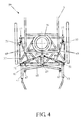
- Fig. 4 shows a plan view of the front part of a further embodiment of the carriage.
- This carriage 59 is to be used as a one-horse carriage and has a steering beam 61 in lieu of a pole.
- the steering beam 61 extends transversely to the first element 43 and the first element is connected to the middle of the steering beam.
- At the ends of the steering beam there are coupling elements 63 present to which the harness of a horse can be coupled.
- the carriage further includes a drawbar 65 which extends transversely to the direction of movement and is pivotably coupled in the middle to the steering beam 61.
- the drawbar has at its ends further coupling elements 67 for harnessing a horse.
Landscapes
- Engineering & Computer Science (AREA)
- Mechanical Engineering (AREA)
- Chemical & Material Sciences (AREA)
- Combustion & Propulsion (AREA)
- Transportation (AREA)
- Vehicle Body Suspensions (AREA)
- Springs (AREA)
- Control Of Motors That Do Not Use Commutators (AREA)
- Rotary Switch, Piano Key Switch, And Lever Switch (AREA)
Priority Applications (1)
| Application Number | Priority Date | Filing Date | Title |
|---|---|---|---|
| PL09158778T PL2112049T3 (pl) | 2008-04-25 | 2009-04-24 | Wóz wyposażony w stabilizator skrętny |
Applications Claiming Priority (2)
| Application Number | Priority Date | Filing Date | Title |
|---|---|---|---|
| NL2001530 | 2008-04-25 | ||
| NL2001531 | 2008-04-25 |
Publications (2)
| Publication Number | Publication Date |
|---|---|
| EP2112049A1 true EP2112049A1 (de) | 2009-10-28 |
| EP2112049B1 EP2112049B1 (de) | 2011-03-16 |
Family
ID=40790598
Family Applications (1)
| Application Number | Title | Priority Date | Filing Date |
|---|---|---|---|
| EP09158778A Active EP2112049B1 (de) | 2008-04-25 | 2009-04-24 | Kutsche mit Wankstabilisator |
Country Status (5)
| Country | Link |
|---|---|
| EP (1) | EP2112049B1 (de) |
| AT (1) | ATE501918T1 (de) |
| DE (1) | DE602009000876D1 (de) |
| NL (1) | NL2002805C2 (de) |
| PL (1) | PL2112049T3 (de) |
Citations (7)
| Publication number | Priority date | Publication date | Assignee | Title |
|---|---|---|---|---|
| DE762834C (de) * | 1939-03-12 | 1952-09-29 | Hans O Schroeter | Ausgleichvorrichtung fuer Kraft- und landwirtschaftliche Fahrzeuge, insbesondere Anhaenger |
| US3194336A (en) * | 1961-11-21 | 1965-07-13 | Ford Motor Co | Vehicle rear suspension |
| EP0225851A2 (de) * | 1985-12-03 | 1987-06-16 | Karl Iseli | Radaufhängevorrichtung für ein langsam fahrendes, geländegängiges Fahrzeug, insbesondere für einen Pferdewagen |
| EP0122527B1 (de) * | 1983-04-08 | 1988-11-30 | Maschinenfabrik Bernard Krone GmbH | Anhängefahrzeug |
| EP0468086A1 (de) * | 1990-07-24 | 1992-01-29 | Kuhnle Gmbh | Kutsche mit einer lenkbaren Achse |
| JPH0532115A (ja) * | 1991-07-29 | 1993-02-09 | Nhk Spring Co Ltd | 車両用スタビライザ装置 |
| JP2003112510A (ja) * | 2001-10-03 | 2003-04-15 | Nhk Spring Co Ltd | 車両用スタビライザ装置 |
-
2009
- 2009-04-24 AT AT09158778T patent/ATE501918T1/de not_active IP Right Cessation
- 2009-04-24 EP EP09158778A patent/EP2112049B1/de active Active
- 2009-04-24 DE DE602009000876T patent/DE602009000876D1/de active Active
- 2009-04-24 NL NL2002805A patent/NL2002805C2/nl not_active IP Right Cessation
- 2009-04-24 PL PL09158778T patent/PL2112049T3/pl unknown
Patent Citations (7)
| Publication number | Priority date | Publication date | Assignee | Title |
|---|---|---|---|---|
| DE762834C (de) * | 1939-03-12 | 1952-09-29 | Hans O Schroeter | Ausgleichvorrichtung fuer Kraft- und landwirtschaftliche Fahrzeuge, insbesondere Anhaenger |
| US3194336A (en) * | 1961-11-21 | 1965-07-13 | Ford Motor Co | Vehicle rear suspension |
| EP0122527B1 (de) * | 1983-04-08 | 1988-11-30 | Maschinenfabrik Bernard Krone GmbH | Anhängefahrzeug |
| EP0225851A2 (de) * | 1985-12-03 | 1987-06-16 | Karl Iseli | Radaufhängevorrichtung für ein langsam fahrendes, geländegängiges Fahrzeug, insbesondere für einen Pferdewagen |
| EP0468086A1 (de) * | 1990-07-24 | 1992-01-29 | Kuhnle Gmbh | Kutsche mit einer lenkbaren Achse |
| JPH0532115A (ja) * | 1991-07-29 | 1993-02-09 | Nhk Spring Co Ltd | 車両用スタビライザ装置 |
| JP2003112510A (ja) * | 2001-10-03 | 2003-04-15 | Nhk Spring Co Ltd | 車両用スタビライザ装置 |
Also Published As
| Publication number | Publication date |
|---|---|
| NL2002805C2 (nl) | 2009-10-27 |
| ATE501918T1 (de) | 2011-04-15 |
| DE602009000876D1 (de) | 2011-04-28 |
| PL2112049T3 (pl) | 2011-10-31 |
| EP2112049B1 (de) | 2011-03-16 |
Similar Documents
| Publication | Publication Date | Title |
|---|---|---|
| CN107848581B (zh) | 用于商用车的驾驶室支承组件 | |
| US9010782B2 (en) | Vehicle with a four bar link suspension system provided with improved roll characteristics | |
| US9242672B2 (en) | Utility vehicle | |
| US20220212527A1 (en) | Subframe and suspension assembly | |
| JP5514808B2 (ja) | サスペンション装置 | |
| US7384052B2 (en) | Suspension and steering system | |
| CN102892595B (zh) | 独立后悬挂 | |
| CN104520178B (zh) | 用于具有两个可侧向倾斜的前轮的车辆的转向轴 | |
| US7798507B2 (en) | Vehicle suspension apparatus | |
| CN102745032B (zh) | 用于机动车车桥的车轮悬架 | |
| WO2011133258A4 (en) | Vehicle suspension system | |
| US9216778B1 (en) | Cab suspension | |
| KR20150087406A (ko) | 차량의 휠 서스펜션을 위한 스태빌라이저 장치 | |
| US6886840B2 (en) | Heavy duty trailing arm suspension system | |
| US6805370B2 (en) | Independently-suspended rear corner module for motor vehicle chassis featuring shackled leaf spring | |
| US6962360B1 (en) | Air suspension anti-roll stabilization system | |
| EP2112049B1 (de) | Kutsche mit Wankstabilisator | |
| US20020109325A1 (en) | Tri-link suspension system | |
| US11772716B1 (en) | Suspension system for an operator station of a work vehicle | |
| WO2010136095A1 (de) | Schwingungsisolierte radachse für kraftfahrzeug | |
| CN105365513A (zh) | 四点连接件 | |
| US10639954B2 (en) | Multi-link suspension system | |
| CN107107692B (zh) | 用于机动车辆车桥的转向节 | |
| US20060170175A1 (en) | Pivoting shackle plate with angled connection to steering axle | |
| JPH07251615A (ja) | 車両用懸架装置 |
Legal Events
| Date | Code | Title | Description |
|---|---|---|---|
| PUAI | Public reference made under article 153(3) epc to a published international application that has entered the european phase |
Free format text: ORIGINAL CODE: 0009012 |
|
| AK | Designated contracting states |
Kind code of ref document: A1 Designated state(s): AT BE BG CH CY CZ DE DK EE ES FI FR GB GR HR HU IE IS IT LI LT LU LV MC MK MT NL NO PL PT RO SE SI SK TR |
|
| 17P | Request for examination filed |
Effective date: 20100428 |
|
| GRAP | Despatch of communication of intention to grant a patent |
Free format text: ORIGINAL CODE: EPIDOSNIGR1 |
|
| GRAS | Grant fee paid |
Free format text: ORIGINAL CODE: EPIDOSNIGR3 |
|
| GRAA | (expected) grant |
Free format text: ORIGINAL CODE: 0009210 |
|
| AK | Designated contracting states |
Kind code of ref document: B1 Designated state(s): AT BE BG CH CY CZ DE DK EE ES FI FR GB GR HR HU IE IS IT LI LT LU LV MC MK MT NL NO PL PT RO SE SI SK TR |
|
| REG | Reference to a national code |
Ref country code: GB Ref legal event code: FG4D |
|
| REG | Reference to a national code |
Ref country code: CH Ref legal event code: EP |
|
| REG | Reference to a national code |
Ref country code: IE Ref legal event code: FG4D |
|
| REF | Corresponds to: |
Ref document number: 602009000876 Country of ref document: DE Date of ref document: 20110428 Kind code of ref document: P |
|
| REG | Reference to a national code |
Ref country code: DE Ref legal event code: R096 Ref document number: 602009000876 Country of ref document: DE Effective date: 20110428 |
|
| REG | Reference to a national code |
Ref country code: NL Ref legal event code: T3 |
|
| PG25 | Lapsed in a contracting state [announced via postgrant information from national office to epo] |
Ref country code: SE Free format text: LAPSE BECAUSE OF FAILURE TO SUBMIT A TRANSLATION OF THE DESCRIPTION OR TO PAY THE FEE WITHIN THE PRESCRIBED TIME-LIMIT Effective date: 20110316 Ref country code: HR Free format text: LAPSE BECAUSE OF FAILURE TO SUBMIT A TRANSLATION OF THE DESCRIPTION OR TO PAY THE FEE WITHIN THE PRESCRIBED TIME-LIMIT Effective date: 20110316 Ref country code: NO Free format text: LAPSE BECAUSE OF FAILURE TO SUBMIT A TRANSLATION OF THE DESCRIPTION OR TO PAY THE FEE WITHIN THE PRESCRIBED TIME-LIMIT Effective date: 20110616 Ref country code: GR Free format text: LAPSE BECAUSE OF FAILURE TO SUBMIT A TRANSLATION OF THE DESCRIPTION OR TO PAY THE FEE WITHIN THE PRESCRIBED TIME-LIMIT Effective date: 20110617 Ref country code: LV Free format text: LAPSE BECAUSE OF FAILURE TO SUBMIT A TRANSLATION OF THE DESCRIPTION OR TO PAY THE FEE WITHIN THE PRESCRIBED TIME-LIMIT Effective date: 20110316 Ref country code: LT Free format text: LAPSE BECAUSE OF FAILURE TO SUBMIT A TRANSLATION OF THE DESCRIPTION OR TO PAY THE FEE WITHIN THE PRESCRIBED TIME-LIMIT Effective date: 20110316 |
|
| LTIE | Lt: invalidation of european patent or patent extension |
Effective date: 20110316 |
|
| REG | Reference to a national code |
Ref country code: ES Ref legal event code: FG2A Ref document number: 2364225 Country of ref document: ES Kind code of ref document: T3 Effective date: 20110829 |
|
| PG25 | Lapsed in a contracting state [announced via postgrant information from national office to epo] |
Ref country code: AT Free format text: LAPSE BECAUSE OF FAILURE TO SUBMIT A TRANSLATION OF THE DESCRIPTION OR TO PAY THE FEE WITHIN THE PRESCRIBED TIME-LIMIT Effective date: 20110316 Ref country code: SI Free format text: LAPSE BECAUSE OF FAILURE TO SUBMIT A TRANSLATION OF THE DESCRIPTION OR TO PAY THE FEE WITHIN THE PRESCRIBED TIME-LIMIT Effective date: 20110316 Ref country code: FI Free format text: LAPSE BECAUSE OF FAILURE TO SUBMIT A TRANSLATION OF THE DESCRIPTION OR TO PAY THE FEE WITHIN THE PRESCRIBED TIME-LIMIT Effective date: 20110316 Ref country code: BG Free format text: LAPSE BECAUSE OF FAILURE TO SUBMIT A TRANSLATION OF THE DESCRIPTION OR TO PAY THE FEE WITHIN THE PRESCRIBED TIME-LIMIT Effective date: 20110616 Ref country code: CY Free format text: LAPSE BECAUSE OF FAILURE TO SUBMIT A TRANSLATION OF THE DESCRIPTION OR TO PAY THE FEE WITHIN THE PRESCRIBED TIME-LIMIT Effective date: 20110316 |
|
| PG25 | Lapsed in a contracting state [announced via postgrant information from national office to epo] |
Ref country code: PT Free format text: LAPSE BECAUSE OF FAILURE TO SUBMIT A TRANSLATION OF THE DESCRIPTION OR TO PAY THE FEE WITHIN THE PRESCRIBED TIME-LIMIT Effective date: 20110718 Ref country code: EE Free format text: LAPSE BECAUSE OF FAILURE TO SUBMIT A TRANSLATION OF THE DESCRIPTION OR TO PAY THE FEE WITHIN THE PRESCRIBED TIME-LIMIT Effective date: 20110316 |
|
| REG | Reference to a national code |
Ref country code: PL Ref legal event code: T3 |
|
| REG | Reference to a national code |
Ref country code: HU Ref legal event code: AG4A Ref document number: E011555 Country of ref document: HU |
|
| PG25 | Lapsed in a contracting state [announced via postgrant information from national office to epo] |
Ref country code: MC Free format text: LAPSE BECAUSE OF NON-PAYMENT OF DUE FEES Effective date: 20110430 Ref country code: CZ Free format text: LAPSE BECAUSE OF FAILURE TO SUBMIT A TRANSLATION OF THE DESCRIPTION OR TO PAY THE FEE WITHIN THE PRESCRIBED TIME-LIMIT Effective date: 20110316 Ref country code: RO Free format text: LAPSE BECAUSE OF FAILURE TO SUBMIT A TRANSLATION OF THE DESCRIPTION OR TO PAY THE FEE WITHIN THE PRESCRIBED TIME-LIMIT Effective date: 20110316 Ref country code: IS Free format text: LAPSE BECAUSE OF FAILURE TO SUBMIT A TRANSLATION OF THE DESCRIPTION OR TO PAY THE FEE WITHIN THE PRESCRIBED TIME-LIMIT Effective date: 20110716 Ref country code: SK Free format text: LAPSE BECAUSE OF FAILURE TO SUBMIT A TRANSLATION OF THE DESCRIPTION OR TO PAY THE FEE WITHIN THE PRESCRIBED TIME-LIMIT Effective date: 20110316 |
|
| PG25 | Lapsed in a contracting state [announced via postgrant information from national office to epo] |
Ref country code: MT Free format text: LAPSE BECAUSE OF FAILURE TO SUBMIT A TRANSLATION OF THE DESCRIPTION OR TO PAY THE FEE WITHIN THE PRESCRIBED TIME-LIMIT Effective date: 20110316 |
|
| PLBE | No opposition filed within time limit |
Free format text: ORIGINAL CODE: 0009261 |
|
| STAA | Information on the status of an ep patent application or granted ep patent |
Free format text: STATUS: NO OPPOSITION FILED WITHIN TIME LIMIT |
|
| REG | Reference to a national code |
Ref country code: IE Ref legal event code: MM4A |
|
| 26N | No opposition filed |
Effective date: 20111219 |
|
| REG | Reference to a national code |
Ref country code: FR Ref legal event code: ST Effective date: 20120210 |
|
| REG | Reference to a national code |
Ref country code: DE Ref legal event code: R097 Ref document number: 602009000876 Country of ref document: DE Effective date: 20111219 |
|
| PG25 | Lapsed in a contracting state [announced via postgrant information from national office to epo] |
Ref country code: FR Free format text: LAPSE BECAUSE OF NON-PAYMENT OF DUE FEES Effective date: 20110516 Ref country code: IE Free format text: LAPSE BECAUSE OF NON-PAYMENT OF DUE FEES Effective date: 20110424 |
|
| PG25 | Lapsed in a contracting state [announced via postgrant information from national office to epo] |
Ref country code: IT Free format text: LAPSE BECAUSE OF FAILURE TO SUBMIT A TRANSLATION OF THE DESCRIPTION OR TO PAY THE FEE WITHIN THE PRESCRIBED TIME-LIMIT Effective date: 20110316 |
|
| PG25 | Lapsed in a contracting state [announced via postgrant information from national office to epo] |
Ref country code: MK Free format text: LAPSE BECAUSE OF FAILURE TO SUBMIT A TRANSLATION OF THE DESCRIPTION OR TO PAY THE FEE WITHIN THE PRESCRIBED TIME-LIMIT Effective date: 20110316 |
|
| PG25 | Lapsed in a contracting state [announced via postgrant information from national office to epo] |
Ref country code: LU Free format text: LAPSE BECAUSE OF NON-PAYMENT OF DUE FEES Effective date: 20110424 |
|
| PG25 | Lapsed in a contracting state [announced via postgrant information from national office to epo] |
Ref country code: TR Free format text: LAPSE BECAUSE OF FAILURE TO SUBMIT A TRANSLATION OF THE DESCRIPTION OR TO PAY THE FEE WITHIN THE PRESCRIBED TIME-LIMIT Effective date: 20110316 |
|
| REG | Reference to a national code |
Ref country code: CH Ref legal event code: PL |
|
| GBPC | Gb: european patent ceased through non-payment of renewal fee |
Effective date: 20130424 |
|
| PG25 | Lapsed in a contracting state [announced via postgrant information from national office to epo] |
Ref country code: LI Free format text: LAPSE BECAUSE OF NON-PAYMENT OF DUE FEES Effective date: 20130430 Ref country code: GB Free format text: LAPSE BECAUSE OF NON-PAYMENT OF DUE FEES Effective date: 20130424 Ref country code: CH Free format text: LAPSE BECAUSE OF NON-PAYMENT OF DUE FEES Effective date: 20130430 |
|
| PGFP | Annual fee paid to national office [announced via postgrant information from national office to epo] |
Ref country code: NL Payment date: 20250401 Year of fee payment: 17 |
|
| PGFP | Annual fee paid to national office [announced via postgrant information from national office to epo] |
Ref country code: DE Payment date: 20250422 Year of fee payment: 17 Ref country code: PL Payment date: 20250410 Year of fee payment: 17 |
|
| PGFP | Annual fee paid to national office [announced via postgrant information from national office to epo] |
Ref country code: ES Payment date: 20250529 Year of fee payment: 17 |
|
| PGFP | Annual fee paid to national office [announced via postgrant information from national office to epo] |
Ref country code: BE Payment date: 20250418 Year of fee payment: 17 |
|
| PGFP | Annual fee paid to national office [announced via postgrant information from national office to epo] |
Ref country code: HU Payment date: 20251008 Year of fee payment: 17 |