EP2112072A2 - Riemenangetriebene Klemmanordnung zum Greifen und Befördern von Bahnmaterial in einer Verpackungsmaschine - Google Patents
Riemenangetriebene Klemmanordnung zum Greifen und Befördern von Bahnmaterial in einer Verpackungsmaschine Download PDFInfo
- Publication number
- EP2112072A2 EP2112072A2 EP09154298A EP09154298A EP2112072A2 EP 2112072 A2 EP2112072 A2 EP 2112072A2 EP 09154298 A EP09154298 A EP 09154298A EP 09154298 A EP09154298 A EP 09154298A EP 2112072 A2 EP2112072 A2 EP 2112072A2
- Authority
- EP
- European Patent Office
- Prior art keywords
- belt
- jaw member
- web material
- drive
- plane
- Prior art date
- Legal status (The legal status is an assumption and is not a legal conclusion. Google has not performed a legal analysis and makes no representation as to the accuracy of the status listed.)
- Granted
Links
Images


Classifications
-
- B—PERFORMING OPERATIONS; TRANSPORTING
- B65—CONVEYING; PACKING; STORING; HANDLING THIN OR FILAMENTARY MATERIAL
- B65B—MACHINES, APPARATUS OR DEVICES FOR, OR METHODS OF, PACKAGING ARTICLES OR MATERIALS; UNPACKING
- B65B9/00—Enclosing successive articles, or quantities of material, e.g. liquids or semiliquids, in flat, folded, or tubular webs of flexible sheet material; Subdividing filled flexible tubes to form packages
- B65B9/02—Enclosing successive articles, or quantities of material between opposed webs
- B65B9/04—Enclosing successive articles, or quantities of material between opposed webs one or both webs being formed with pockets for the reception of the articles, or of the quantities of material
-
- B—PERFORMING OPERATIONS; TRANSPORTING
- B65—CONVEYING; PACKING; STORING; HANDLING THIN OR FILAMENTARY MATERIAL
- B65B—MACHINES, APPARATUS OR DEVICES FOR, OR METHODS OF, PACKAGING ARTICLES OR MATERIALS; UNPACKING
- B65B31/00—Packaging articles or materials under special atmospheric or gaseous conditions; Adding propellants to aerosol containers
- B65B31/02—Filling, closing, or filling and closing, containers or wrappers in chambers maintained under vacuum or superatmospheric pressure or containing a special atmosphere, e.g. of inert gas
- B65B31/021—Filling, closing, or filling and closing, containers or wrappers in chambers maintained under vacuum or superatmospheric pressure or containing a special atmosphere, e.g. of inert gas the containers or wrappers being interconnected
-
- B—PERFORMING OPERATIONS; TRANSPORTING
- B65—CONVEYING; PACKING; STORING; HANDLING THIN OR FILAMENTARY MATERIAL
- B65B—MACHINES, APPARATUS OR DEVICES FOR, OR METHODS OF, PACKAGING ARTICLES OR MATERIALS; UNPACKING
- B65B41/00—Supplying or feeding container-forming sheets or wrapping material
- B65B41/12—Feeding webs from rolls
- B65B41/14—Feeding webs from rolls by grippers
-
- B—PERFORMING OPERATIONS; TRANSPORTING
- B65—CONVEYING; PACKING; STORING; HANDLING THIN OR FILAMENTARY MATERIAL
- B65B—MACHINES, APPARATUS OR DEVICES FOR, OR METHODS OF, PACKAGING ARTICLES OR MATERIALS; UNPACKING
- B65B47/00—Apparatus or devices for forming pockets or receptacles in or from sheets, blanks, or webs, comprising essentially a die into which the material is pressed or a folding die through which the material is moved
- B65B47/04—Apparatus or devices for forming pockets or receptacles in or from sheets, blanks, or webs, comprising essentially a die into which the material is pressed or a folding die through which the material is moved by application of mechanical pressure
- B65B47/06—Apparatus or devices for forming pockets or receptacles in or from sheets, blanks, or webs, comprising essentially a die into which the material is pressed or a folding die through which the material is moved by application of mechanical pressure using folding dies
-
- B—PERFORMING OPERATIONS; TRANSPORTING
- B65—CONVEYING; PACKING; STORING; HANDLING THIN OR FILAMENTARY MATERIAL
- B65B—MACHINES, APPARATUS OR DEVICES FOR, OR METHODS OF, PACKAGING ARTICLES OR MATERIALS; UNPACKING
- B65B19/00—Packaging rod-shaped or tubular articles susceptible to damage by abrasion or pressure, e.g. cigarettes, cigars, macaroni, spaghetti, drinking straws or welding electrodes
- B65B19/34—Packaging other rod-shaped articles, e.g. sausages, macaroni, spaghetti, drinking straws, welding electrodes
-
- B—PERFORMING OPERATIONS; TRANSPORTING
- B65—CONVEYING; PACKING; STORING; HANDLING THIN OR FILAMENTARY MATERIAL
- B65B—MACHINES, APPARATUS OR DEVICES FOR, OR METHODS OF, PACKAGING ARTICLES OR MATERIALS; UNPACKING
- B65B25/00—Packaging other articles presenting special problems
- B65B25/06—Packaging slices or specially-shaped pieces of meat, cheese, or other plastic or tacky products
Definitions
- the present invention relates generally to packaging systems that deform a web of flexible material into product-holding cavities and, more particularly, to a belt-driven clamping arrangement that advances the web of flexible material through the various stations of a packaging system.
- prior art packaging machines utilizing a chain-type clamping arrangement involve the use of a drive motor that rotates a drive shaft, and a pair of drive sprockets that are mounted to the drive shave. Each drive sprocket is engaged with one of the clip chains.
- the drive shaft extends across the width of the packaging machine, and is operable to synchronously drive the drive sprockets so as to move the clip chains together.
- the components of the machine must be arranged so as to provide clearance for the drive shaft.
- this arrangement can result in the opposite edges of the web material being advanced at slightly different rates of speed through the machine, which can cause skewing and wrinkling of the web material.
- a material advancement apparatus for carrying web material through a packaging machine.
- the apparatus includes a motor assembly and a belt operatively driven by the motor assembly along a predetermined path.
- the apparatus further includes a clamp arrangement including a plurality of clamps coupled to the belt and adapted to selectively grip and release the web material.
- the invention contemplates a packaging machine having a formation station that deforms a web of flexible material to form a cavity adapted to receive a product to be packaged.
- the packaging machine further has a supply of flexible web material and a belt assembly associated with the supply of flexible web material and operable to advance the web material along a continuous and predetermined path to the formation station.
- the present invention includes a clamping arrangement for a packaging machine that packages products in flexible web material.
- the clamping arrangement includes a plurality of clamps, each of which has a channel guide member adapted to engage a guide of the packaging machine, a lower jaw member coupled to the channel guide member, and an upper jaw member coupled to the lower jaw member in a manner that allows the upper jaw member to pivot relative to the lower jaw member.
- the present invention includes a pair of spaced apart, endless web material advancement components on opposite sides of the machine, which are operable to grip the edges of the web material.
- a drive arrangement is engaged with the web material advancement components, and includes a pair of drive motors located one on each side of the machine. Each drive motor is engaged with one of the web material advancement components, and the drive motors are operated synchronously in order to move the opposite edges of the web material at the same rate of speed through the machine.
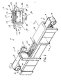
- FIG. 1 illustrates a packaging machine 10 that generally includes a lower web supply station 12 for supplying a lower web 14 of flexible web material from a supply roll 16 to a formation station 18.
- the lower web 14 of flexible material is advanced to the formation station 18, where cavities 20 are formed in the lower web 14.
- the deformed lower web 14 is then presented to a loading station 22 where a user or machine loads products, e.g., hot dogs, cheese, meat or any other edible or non-edible product, into the cavities 20.
- products e.g., hot dogs, cheese, meat or any other edible or non-edible product
- the evacuation and sealing station 30 may include a web heating assembly that heats and bonds the upper web 26 and the lower web 14 together.
- the sealed packages may then be presented to a cutting station (not shown) for separating the product packages formed by the sealed upper and lower webs, a labeling station (not shown), and a bulk packaging station (not shown) as generally understood in the art.
- the packing machine 10 may also include a control unit 32 that presents a touch screen, for instance, to allow a user to control the packaging machine 10 while proximate the loading station 22.
- a frame assembly that includes a pair of spaced parallel upper frame members 34, and lower spaced frame members such as shown at 36, 38, and 40.
- Legs 42 support the frame members in a raised position above a support surface such as a floor 44.
- the formation station 18 includes a lift mechanism 46 that functions to move a formation box 48 between a lowered position and a raised position.
- the formation box 48 is defined by a series of side walls 50 that extend upwardly from a base 52.
- the spacing between the side walls 50 and the base 52 collectively form cavities 54 that may be evacuated using a vacuum (not shown) so as to draw the lower web material 14 into the cavities 54. More particularly, when the formation box 48 is in its fully raised position, the formation box 48 abuts an underside of lower web material 14. The cavities 54 may then be evacuated to draw the lower web 14 of flexible material downward into the cavities 54.
- Separate stamps or plug assist members 56 may also be used to help force the lower web 14 of flexible material into cavities 54 so as to deform the lower web 14 of flexible material. This process forms a number of cavities 20 in the lower web 14, which are adapted to receive product(s) to be packaged, as described with respect to FIG. 1 ).
- the formation box 48 is supported by a rack or frame 58 that includes a pair of plates 60, 62 oriented parallel to one another and coupled by a pair of braces 64, 66.
- the formation box 48 is mounted to the frame 58 by brackets 67.
- the braces 64, 66 hold the plates 60, 62 so that a slot 68 is formed between the plates 60, 62.
- the slot 68 defines a track along which a pair of rollers 70, 72 may translate.
- the rollers 70, 72 are each coupled to an arm 74, 76, respectively, which are connected to carriages 78, 80, respectively.
- each carriage 78, 80 supports a pair of arms, of which a single arm is shown for each carriage in FIG. 2 .
- the carriages 78, 80 are coupled, in a fixed connection, to a driven belt 90 that is trained around a driven pulley or wheel 92 and an idler pulley or follower wheel 94. As illustrated in FIG. 4 , carriage 78 is connected to a lower run or belt portion 96 and carriage 80 is connected to an upper run or belt portion 98.
- the driven wheel 92 is driven by a drive belt 100 trained about the driven wheel 92 and a drive wheel 102.
- rotation of drive wheel 102 causes rotation of driven wheel 92.
- the driven belt 90 is rotated about its path defined by driven wheel 92 and follower wheel 94.
- Rotation of the driven belt 90 in a clockwise direction resulting from a clockwise rotation of driven wheel 92, causes the carriages 78, 80 to move away from one another.
- the driven belt 90 causes carriage 78 to move toward the driven wheel 92 and causes carriage 80 to move toward the follower wheel 94.
- This movement also causes arms 74, 76 to pivot about pivots 82, 84, respectively.
- the arms 74, 76 are caused to pivot about pivots 86, 88, respectively.
- the driven belt 90 is a slave to the drive belt 100, such that the driven belt 90 is not translated along its rotational path until the drive belt 100 is translated along its rotational path.
- the sealing station 30 includes a lift mechanism 104 similar to that shown for the formation station 18 shown and described above with respect to FIG. 4 .
- the lift mechanism 104 functions to raise and lower a tool in the form of a sealing anvil, which is used in sealing the upper and lower webs together in a manner as is known.
- the lower web 14 of flexible material is advanced from supply roll 16 through the formation station 18, the loading station 22, and to the upper web station 26 by a pair of belts 106, 108.
- Each belt 106, 108 is made up of separate side-by-side belt portions 110, 112 and 114, 116, respectively.
- the side-by-side belt portions 110, 112 and 114, 116 carry an array of clamps 118 that selectively grip and release edges of the lower web 14 of flexible material.
- the belts 106, 108 are trained about a respective pair of wheels, of which wheels 120, 122 associated with belt 106 are seen in FIGS. 2 and 4 .
- One of the wheels 124 associated with belt 108 may be seen in FIG. 3 .
- wheel 120 which is a drive wheel driven by a motor assembly 126, is located at or near the upper web station 24, whereas wheel 122 is a driven wheel posited at or near the supply roll 16. It is also understood that wheel 122 may be driven by a motor assembly. Further, it is also contemplated that both wheels 120, 122 may be separately motor driven. In a similar manner, wheel 124 is also a driven wheel and is rotated by a separate drive wheel (not shown), opposite drive wheel 120, via translation of belt 108.
- each clamp 118 is composed of a movable upper jaw member 128 and a fixed lower jaw member 130.
- the lower jaw member 130 is coupled to a channel guide member 132 by a pair of screws 134.
- a pivot pin 136 extends through openings 138 in a pair of spaced apart sidewalls 139 of the upper jaw member 128, and through openings 140 formed in a pair of downwardly extending tongues 142 of lower jaw member 130, of which only one tongue 142 is shown, to pivotably connect the upper jaw member 128 and the lower jaw member 130 to one another.
- a spring 144 defines a lower end that is seated on a pair of spaced apart, upwardly extending flanges 146 formed on a pair of lower tab member of the upper jaw member 128, to centrally position the spring 144 relative to the upper jaw member 128.
- the upper jaw member 128 has a relatively flat and planar upper wall 148 with a sloped face or front wall 150 extending therefrom.
- the sloped face 150 has a serrated leading edge 152 that defines a series of gripping teeth 154.
- the lower jaw member 130 also a relatively flat and planar upper wall 156, but lacks the sloped face of the upper jaw member 128.
- the flat upper wall 156 of lower jaw member 130 has an alignment guide 157 which is configured to extend downwardly below the plane of upper wall 156, for engagement with the upper end of the spring 144 to align the spring 144 with the lower jaw member 180.
- the flat upper wall 156 of the lower jaw member 130 also has a serrated leading edge 158 defining a series of gripping teeth 160 that work in concert with the gripping teeth 154 of the upper jaw member 128 to grip the web of flexible material 14.
- the upper jaw member 128 is selectively movable relative to the lower jaw member 130 between open and closed positions.
- the teeth 154 of the upper jaw member 128 engage the teeth 160 of upper jaw member 130, so as to clamp an edge area of the web of flexible material therebetween.
- Spring 144 functions to apply a downward biasing force on upper jaw member 128 at a location forwardly of pivot pin 136, to urge upper jaw member 128 toward the closed position.
- upper jaw member 128 is pivoted about pivot pin 136 against the biasing force of spring 144, so as to move teeth 154 of upper jaw member 128 apart from the teeth 160 of lower jaw member 130.
- the upper jaw member 128 may be controlled in a known manner to pivot upwardly to the open position about pivot pin 136 against the bias of spring 144, to release the web of flexible material.
- the upper jaw member 128 and the lower jaw member 130 are configured such that the respective teeth 154, 160 grip the web of flexible material along a plane that is generally parallel and between the plane of the upper walls 148, 156 of the upper jaw member and the lower jaw member, respectively.
- the plane on which the teeth 154, 160 grip the web of flexible material is preferably generally along a plane defined by the upper surface of the planar upper wall 156 of lower jaw member 130.
- the channel guide member 132 has a relatively flat upper wall 162 and a pair of legs 164 extending downwardly from the edges 166 of the upper wall 162 at an angle that is perpendicular to the plane of the upper wall 162.
- Each leg 164 has an arm 168 extending perpendicularly from the leg 164 and in a plane parallel to that of the upper wall 162.
- the upper wall 162, legs 164, and arms 168 collectively define a C-shaped receiver, which is configured for engagement with a guide member 169 ( FIG. 3 ).
- Each guide member 169 may be in the form of a guide block or rail formed of a low friction material, and which includes oppositely facing guide slots 171 within which arms 168 are adapted to be received. In this manner, the guide member 169 functions to axially guide movement of the belts 106, 108 along the length of the packaging machine 10.
- Lower jaw member 130 includes a pair of axially spaced, upwardly extending protrusions 173 formed in upper wall 156.
- channel guide member 132 includes a pair of axially spaced, upwardly extending protrusions 175 formed in upper wall 162. The spacing between protrusions 173 is generally equal to the spacing between protrusions 175.
- each clamp 118 may be secured to the belt 108 in a desired position along the length of the belt 108. As shown in FIG.
- each belt 106, 108 is formed with teeth 177 along its length, which are configured for engagement with mating teeth on the wheels such as 120, 122, 124 to provide positive engagement between the belts 106, 108 and the associated wheels such as 120, 122, 124.
- the axial spacing between the protrusions 173 and the protrusions 175 matches the spacing between the belt teeth 177, such that the protrusions 173 are engaged within the spaces between a pair of adjacent teeth 177 when the lower jaw member 130 and the channel guide member 132 are secured together.
- the protrusions 177 provide an area of relief into which the area of the belt 106, 108 is received, to positively secure each clamp 118 axially along the length of the belt 106, 108.
- the belts 106, 108 are formed of respective side-by-side belt portions 110, 112 and 114, 116.
- the clamps 118 are used to splice or secure the ends of the belt portions 110, 112, 114 and 116.
- the ends of the belt portion 116 are positioned adjacent each other, between the protrusions 175, 177 of channel guide member 132 and lower jaw member 130, respectively.
- the clamp 118 is then secured over the adjacent ends of the belt portion 116, so that clamp 118 functions to maintain the ends of belt portion 116 together.
- the ends of the adjacent belt portion 114 are secured together in a similar manner.
- the ends of the adjacent belt portion 114 are secured together using a different one of clamps 118 than is used to secure together the ends of the belt portion 116, to provide an axially offset or staggered splice configuration.
- the ends of the adjacent belt portion 114 may be secured together using a clamp 118 that is immediately adjacent the clamp 118 that is used to secured the ends of belt portion 116 together, although it is understood that any other clamp 118 at any other position along the length of the belt portion 116 may be used to secure the ends of the belt portion 114 together.
- FIG. 6 an enlarged view of a portion of the formation station shows belt 106 trained about a guide roller 170 and around driven wheel 122.
- the clamps 118 remain connected to the belt 106 as the belt is translated by the driven wheel 124 and the drive wheel 120, FIG. 2 .
- Each wheel includes circumferentially spaced recesses 179, which are configured to receive the channel guide members 132 of the clamps 118.
- the clamps 118 are designed to rotate with the belt 106, and to be moved to an open position as the clamp approached the web supply area, such as by operation of a cam-type opening arrangement as is known.
- the opening mechanism allows each clamp 118 to move to the closed position by operation of the spring 144, such that the gripping teeth 154, 160 of the respective upper and lower jaw members 128, 130 grip the web of flexible material and then advance the web material with the belt 106 in an indexed manner, although it is understood that the web of material may also be advanced in a continuous manner.
- the clamps 118 are engaged with the guide member 169 when discharged from the wheel 122, to maintain consistent travel of the belt 106 along the length of the packaging machine 10.
- the packaging machine 10 includes two belts 106, 108 spaced from one another, and each of which includes clamps 118 to grip and advance the web 14 of flexible material from the supply roll 16 through the various stations of the packaging machine.
- optical sensors are used to provide feedback to motor controllers (not shown) for the respective motors (motor 126 for belt 106) so that operation of the motors for each belt can be synchronized. It is recognized that other types of sensors may also be used to provide positional feedback to the motor controllers for motor synchronization. Alternately, a single motor could be used to drive the drive wheels and thus the belts.
- the belt-driven clamping mechanism of the present invention has been shown and described as being formed of two side-by-side belts to which the individual clamping assemblies are mounted, it is contemplated that alternate designs are possible and are within the scope of the present invention.
- the belt component may be a single belt, or may be three or more side-by-side belt sections secured together using the clamping assemblies.
- the belt sections are spliced at offset locations using the clamping assemblies, as described above, to distribute stresses across a number of clamping assemblies rather than a single clamping assembly.
- the belt splice may be accomplished different ways in order to distribute splice stresses across several clamping assemblies.
- the belt ends may be cut diagonally at relatively shallow complementary angles, so that the splice spans across a number of clamping assemblies, such as six to eight clamping assemblies.
- the belt ends may have ends with stepped transverse cuts, so that the facing ends of each step are secured together using one of the clamping assemblies.
- a belt cut having any number of steps may be employed, to distribute the splice stresses across a desired number of clamping assemblies.
Landscapes
- Engineering & Computer Science (AREA)
- Mechanical Engineering (AREA)
- Chemical & Material Sciences (AREA)
- Dispersion Chemistry (AREA)
- Basic Packing Technique (AREA)
- Auxiliary Devices For And Details Of Packaging Control (AREA)
- Advancing Webs (AREA)
- Supplying Of Containers To The Packaging Station (AREA)
- Replacement Of Web Rolls (AREA)
Applications Claiming Priority (1)
| Application Number | Priority Date | Filing Date | Title |
|---|---|---|---|
| US12/057,916 US7934362B2 (en) | 2008-03-28 | 2008-03-28 | Belt driven clamping arrangement for gripping and advancing web material in a packaging machine |
Publications (3)
| Publication Number | Publication Date |
|---|---|
| EP2112072A2 true EP2112072A2 (de) | 2009-10-28 |
| EP2112072A3 EP2112072A3 (de) | 2009-11-04 |
| EP2112072B1 EP2112072B1 (de) | 2011-09-21 |
Family
ID=40801994
Family Applications (1)
| Application Number | Title | Priority Date | Filing Date |
|---|---|---|---|
| EP09154298A Active EP2112072B1 (de) | 2008-03-28 | 2009-03-04 | Riemenangetriebene Klemmanordnung zum Greifen und Befördern von Bahnmaterial in einer Verpackungsmaschine |
Country Status (5)
| Country | Link |
|---|---|
| US (2) | US7934362B2 (de) |
| EP (1) | EP2112072B1 (de) |
| AT (1) | ATE525292T1 (de) |
| CA (2) | CA2658863C (de) |
| DK (1) | DK2112072T3 (de) |
Families Citing this family (14)
| Publication number | Priority date | Publication date | Assignee | Title |
|---|---|---|---|---|
| DE102008019626A1 (de) * | 2008-04-18 | 2009-10-29 | Multivac Sepp Haggenmüller Gmbh & Co. Kg | Arbeitsstation einer Verpackungsmaschine mit einer Hubvorrichtung |
| EP2412632B1 (de) * | 2010-07-29 | 2013-07-10 | MULTIVAC Sepp Haggenmüller GmbH & Co KG | Tiefziehverpackungsmachine und Verfahren zum Befüllen von Verpackungsmulden mit Produkten |
| DE102012024725A1 (de) * | 2012-12-18 | 2014-06-18 | Multivac Sepp Haggenmüller Gmbh & Co. Kg | Tiefziehverpackungsmaschine und Verfahren |
| ES2548083T3 (es) | 2013-02-01 | 2015-10-14 | Ulma Packaging Technological Center, S.Coop. | Máquina de termoformado |
| CN112830310A (zh) * | 2013-03-25 | 2021-05-25 | 株式会社汤山制作所 | 药剂分包装置、药剂分包纸余量判断方法和药剂分包纸卷筒 |
| DE102014210963A1 (de) * | 2014-06-06 | 2015-12-17 | Optima consumer GmbH | Antriebsvorrichtung und Station einer Verpackungsmaschine |
| US10526157B2 (en) | 2016-11-04 | 2020-01-07 | Cp Packaging, Inc. | Web material advancement arrangement with an entry drive system in a packaging machine |
| US10961093B2 (en) | 2017-08-14 | 2021-03-30 | Cp Packaging, Inc. | Simplified lift mechanism for a packaging machine |
| CN107685893B (zh) * | 2017-09-21 | 2023-11-21 | 河南中烟工业有限责任公司 | 烟包推送装置及使用该推送装置的包装机 |
| WO2021094581A1 (de) | 2019-11-15 | 2021-05-20 | Gea Food Solutions Germany Gmbh | Materialbahntransportmittel für eine verpackungsmaschine |
| CN112518856B (zh) * | 2020-10-31 | 2023-04-07 | 广州喜登堡床垫机械有限公司 | 一种拉手切送装置 |
| US11999520B2 (en) | 2022-02-11 | 2024-06-04 | Cp Packaging, Llc | System for automatic calibration of an initial position of a moveable machine component |
| CN115043243B (zh) * | 2022-04-13 | 2023-09-22 | 江苏新行健实业有限公司 | 一种不锈钢卷板加工用带有限位结构的输送装置 |
| EP4608750A1 (de) | 2022-10-27 | 2025-09-03 | Gea Food Solutions Germany GmbH | Materialbahnvorzug mittels gewindespindel |
Citations (2)
| Publication number | Priority date | Publication date | Assignee | Title |
|---|---|---|---|---|
| US4915283A (en) | 1988-10-06 | 1990-04-10 | Curwood, Inc. | Clamping arrangement for gripping and carrying web material |
| US5205110A (en) | 1990-12-12 | 1993-04-27 | Buchko Raymond G | Servo motor operated indexing motion packaging machine and method |
Family Cites Families (42)
| Publication number | Priority date | Publication date | Assignee | Title |
|---|---|---|---|---|
| DE839148C (de) | 1941-04-30 | 1952-05-15 | Daimler Benz Ag | Triebwerk fuer die Fernsteuerung von Brennkraftmaschinen |
| US2627756A (en) | 1947-07-24 | 1953-02-10 | Wilfrid H Bendall | Power transmission chain |
| DE834311C (de) | 1949-02-05 | 1952-03-17 | Louis Kuehn | Zwanglaeufige Kraftuebertragung umlaufender Antriebe durch Stahlseile |
| US2770143A (en) | 1951-02-12 | 1956-11-13 | Wilfrid H Bendall | Flexible link chain |
| US2770144A (en) | 1952-06-12 | 1956-11-13 | Wilfrid H Bendall | Flexible link chain |
| FR1215244A (fr) | 1958-11-13 | 1960-04-15 | Perfectionnements aux courroies de transmission à talon | |
| BE627669A (de) | 1962-12-15 | |||
| US3303628A (en) * | 1962-12-17 | 1967-02-14 | Royal Packaging Equipment Inc | Packaging machine and method of forming packages |
| US3282121A (en) | 1964-03-24 | 1966-11-01 | Moog Industries Inc | Drive chain |
| US3773235A (en) * | 1970-10-26 | 1973-11-20 | American Can Co | Packaging apparatus |
| US3728921A (en) * | 1971-04-01 | 1973-04-24 | Hayseen Mfg Co | Apparatus for cutting a web into sheets and positioning the sheets |
| US3768596A (en) | 1972-03-31 | 1973-10-30 | Westinghouse Electric Corp | Elevator compensation chains |
| US3851536A (en) | 1973-02-16 | 1974-12-03 | Rockwell International Corp | Power transmission belt |
| AT356741B (de) * | 1976-08-05 | 1980-05-27 | Kabelschlepp Gmbh | Vorrichtung zum befestigen einer abdeckung an einer energiefuehrungskette |
| US4147069A (en) | 1976-10-01 | 1979-04-03 | Fmc Corporation | Geared belt for positive drive transmission |
| US4170281A (en) | 1977-06-30 | 1979-10-09 | The Laitram Corporation | Extrudable flexible modular tooth driven conveyor belt |
| US4214488A (en) | 1977-10-27 | 1980-07-29 | Dynaloc Corporation | Positive drive system |
| US4336680A (en) * | 1980-01-04 | 1982-06-29 | Nordson Corporation | Stainless steel transport band |
| DE3022065C3 (de) * | 1980-06-12 | 1987-01-02 | Multivac Sepp Haggenmüller KG, 8941 Wolfertschwenden | Transporteinrichtung |
| DE3105891C2 (de) | 1981-02-18 | 1983-12-01 | Thyssen Edelstahlwerke AG, 4000 Düsseldorf | Verwendung eines schweißbaren nichtrostenden Stahles für Kettenglieder |
| US4826065A (en) * | 1983-04-28 | 1989-05-02 | Multivac Sepp Haggenmuller Kg | Feeding means for feeding a machine web in a packaging machine |
| DE3315419A1 (de) | 1983-04-28 | 1984-10-31 | Multivac Sepp Haggenmüller KG, 8941 Wolfertschwenden | Transporteinrichtung zum fuehren einer materialbahn in einer verpackungsmaschine |
| JPS60114204A (ja) * | 1983-11-26 | 1985-06-20 | ワイケイケイ株式会社 | スライドフアスナ−の仕上加工におけるグリツパ−装置 |
| CH665195A5 (de) * | 1984-03-30 | 1988-04-29 | Walter Suter | Verfahren und vorrichtung zum aufeinanderfolgenden transport von dokumenten aus einem zweibahnigen ausdruck. |
| US4987728A (en) * | 1988-05-02 | 1991-01-29 | T W Kutter Inc. | Form, fill, and seal apparatus |
| US4897985A (en) * | 1988-10-06 | 1990-02-06 | Curwood, Inc. | Continuous motion package forming machine |
| US4944442A (en) * | 1988-10-06 | 1990-07-31 | Curwood, Inc. | Web retention and advancement mechanism |
| GB2235678A (en) * | 1989-08-29 | 1991-03-13 | Grace W R & Co | Packaging method and apparatus |
| EP0643810A4 (de) | 1992-05-18 | 1995-08-02 | Proprietary Technology Inc | Endloser biegsamer treibriemen. |
| DK0573810T3 (da) * | 1992-06-04 | 1997-09-22 | Mitsubishi Heavy Ind Ltd | Transportør til at bære og fremføre linned |
| US5443150A (en) * | 1993-09-23 | 1995-08-22 | Rapidpak, Inc. | Apparatus for advancing preformed containers |
| DE29617426U1 (de) | 1996-10-08 | 1997-01-16 | Field, Roger, 81549 München | Riemen |
| GB9704040D0 (en) | 1997-02-27 | 1997-04-16 | Renold Plc | A chain |
| DE19912491A1 (de) * | 1999-03-19 | 2000-09-28 | Multivac Haggenmueller Gmbh | Verpackungsmaschine |
| DE29910372U1 (de) | 1999-06-04 | 1999-08-05 | Arnold & Stolzenberg GmbH, 37574 Einbeck | Rollenkette |
| DE20107003U1 (de) | 2001-04-23 | 2002-09-19 | Igus Spritzgußteile für die Industrie GmbH, 51147 Köln | Energieführungskette |
| US7246699B2 (en) | 2002-03-08 | 2007-07-24 | Frost Links, Inc. | Conveyor chain |
| US6939260B2 (en) | 2002-04-16 | 2005-09-06 | Tesma International Inc. | Silent drive chain assembly having flexible links |
| JP2004028200A (ja) | 2002-06-25 | 2004-01-29 | Mitsuboshi Belting Ltd | 高負荷伝動ベルト |
| DE10351125A1 (de) | 2003-11-03 | 2005-06-02 | Contitech Antriebssysteme Gmbh | Hybridkette |
| DE10354174B4 (de) | 2003-11-19 | 2005-09-15 | Gambs, Martin, Dipl.-Ing. (FH) | Zahnband und Zahnscheibe |
| DE102005038356A1 (de) | 2005-08-11 | 2007-02-22 | Multivac Sepp Haggenmüller Gmbh & Co. Kg | Kette für einen Maschinenantrieb, einen Materialtransport in einer Maschine oder dergleichen und Verpackungsmaschine mit einer solchen Kette |
-
2008
- 2008-03-28 US US12/057,916 patent/US7934362B2/en active Active
-
2009
- 2009-03-04 DK DK09154298.5T patent/DK2112072T3/da active
- 2009-03-04 EP EP09154298A patent/EP2112072B1/de active Active
- 2009-03-04 AT AT09154298T patent/ATE525292T1/de not_active IP Right Cessation
- 2009-03-18 CA CA2658863A patent/CA2658863C/en active Active
- 2009-03-18 CA CA2780896A patent/CA2780896C/en active Active
-
2011
- 2011-02-23 US US13/032,905 patent/US8225586B2/en active Active
Patent Citations (3)
| Publication number | Priority date | Publication date | Assignee | Title |
|---|---|---|---|---|
| US4915283A (en) | 1988-10-06 | 1990-04-10 | Curwood, Inc. | Clamping arrangement for gripping and carrying web material |
| US5205110A (en) | 1990-12-12 | 1993-04-27 | Buchko Raymond G | Servo motor operated indexing motion packaging machine and method |
| US5205110C1 (en) | 1990-12-12 | 2001-05-15 | Dec Int | Servo motor operated indexing motion packaging machine and method |
Also Published As
| Publication number | Publication date |
|---|---|
| CA2780896C (en) | 2014-11-18 |
| EP2112072A3 (de) | 2009-11-04 |
| US8225586B2 (en) | 2012-07-24 |
| CA2780896A1 (en) | 2009-09-28 |
| US20090241486A1 (en) | 2009-10-01 |
| CA2658863C (en) | 2013-07-23 |
| US20110138755A1 (en) | 2011-06-16 |
| US7934362B2 (en) | 2011-05-03 |
| EP2112072B1 (de) | 2011-09-21 |
| DK2112072T3 (da) | 2012-01-09 |
| CA2658863A1 (en) | 2009-09-28 |
| ATE525292T1 (de) | 2011-10-15 |
Similar Documents
| Publication | Publication Date | Title |
|---|---|---|
| EP2112072B1 (de) | Riemenangetriebene Klemmanordnung zum Greifen und Befördern von Bahnmaterial in einer Verpackungsmaschine | |
| EP2105279B1 (de) | Hebemechanismus für Werkzeug, das auf eine Bahn in einer Verpackungsmaschine wirkt | |
| JP5449304B2 (ja) | 積み重ねられた製品を結束する結束システム及び方法 | |
| US6282866B1 (en) | Packaging machine | |
| US6223500B1 (en) | Apparatus and method for wrapping compressible articles with a web-like wrapping material | |
| US6640522B2 (en) | Method and machine for packing reams of sheets | |
| KR101711878B1 (ko) | 연속 작업이 가능한 단열재 자동 커팅 장치 | |
| CA2964383C (en) | Process section of a packaging machine | |
| EP3795315B1 (de) | Automatische maschine zur breitenverleimung von holzlamellen zu laminierten platten beliebiger abmessungen und zugehöriges verfahren | |
| CN103863600A (zh) | 热成形包装机和方法 | |
| JP4188516B2 (ja) | トレイ容器打抜装置 | |
| JP2004345727A (ja) | ラベルの貼付装置 | |
| EP2036819B1 (de) | Verfahren und Anlage zur Zufuhr von Produkten zu einer gruppenbildenden Anlage | |
| ITBO980090A1 (it) | Apparato per il taglio a misura della banda di strappo per confezioni di prodotti e per la preincisione del film di confezionamento lateralm | |
| JP3718130B2 (ja) | 帯掛け包装装置 | |
| CN119460273B (zh) | 型材贴膜设备 | |
| CN100421892C (zh) | 用于送入胶合板板条的设备 | |
| EP1479608B1 (de) | Vorrichtung zur Verpackung von Gegenständen in Schrumpffolie | |
| JP3002194B1 (ja) | コンクリ―ト型枠用堰板へのフィルム貼付方法及びその装置 | |
| JP5520706B2 (ja) | 帯掛けシュリンク包装装置 | |
| JPH0422771B2 (de) | ||
| JPH04279439A (ja) | シート体搬送装置 | |
| JP2004082322A (ja) | 切断装置及び切断方法 | |
| JPH01279012A (ja) | 包装機における搬出装置 | |
| HK1182054A1 (zh) | 用於将食品条切割成片状的方法和装置 |
Legal Events
| Date | Code | Title | Description |
|---|---|---|---|
| PUAI | Public reference made under article 153(3) epc to a published international application that has entered the european phase |
Free format text: ORIGINAL CODE: 0009012 |
|
| PUAL | Search report despatched |
Free format text: ORIGINAL CODE: 0009013 |
|
| AK | Designated contracting states |
Kind code of ref document: A2 Designated state(s): AT BE BG CH CY CZ DE DK EE ES FI FR GB GR HR HU IE IS IT LI LT LU LV MC MK MT NL NO PL PT RO SE SI SK TR |
|
| AX | Request for extension of the european patent |
Extension state: AL BA RS |
|
| AK | Designated contracting states |
Kind code of ref document: A3 Designated state(s): AT BE BG CH CY CZ DE DK EE ES FI FR GB GR HR HU IE IS IT LI LT LU LV MC MK MT NL NO PL PT RO SE SI SK TR |
|
| AX | Request for extension of the european patent |
Extension state: AL BA RS |
|
| 17P | Request for examination filed |
Effective date: 20100429 |
|
| 17Q | First examination report despatched |
Effective date: 20100528 |
|
| AKX | Designation fees paid |
Designated state(s): AT BE BG CH CY CZ DE DK EE ES FI FR GB GR HR HU IE IS IT LI LT LU LV MC MK MT NL NO PL PT RO SE SI SK TR |
|
| GRAP | Despatch of communication of intention to grant a patent |
Free format text: ORIGINAL CODE: EPIDOSNIGR1 |
|
| RIN1 | Information on inventor provided before grant (corrected) |
Inventor name: LONG, DWAYNE C. Inventor name: BUCHKO, RAYMOND G. |
|
| GRAS | Grant fee paid |
Free format text: ORIGINAL CODE: EPIDOSNIGR3 |
|
| GRAA | (expected) grant |
Free format text: ORIGINAL CODE: 0009210 |
|
| AK | Designated contracting states |
Kind code of ref document: B1 Designated state(s): AT BE BG CH CY CZ DE DK EE ES FI FR GB GR HR HU IE IS IT LI LT LU LV MC MK MT NL NO PL PT RO SE SI SK TR |
|
| REG | Reference to a national code |
Ref country code: GB Ref legal event code: FG4D |
|
| REG | Reference to a national code |
Ref country code: CH Ref legal event code: EP |
|
| REG | Reference to a national code |
Ref country code: IE Ref legal event code: FG4D |
|
| REG | Reference to a national code |
Ref country code: DE Ref legal event code: R096 Ref document number: 602009002643 Country of ref document: DE Effective date: 20111117 |
|
| REG | Reference to a national code |
Ref country code: SE Ref legal event code: TRGR |
|
| REG | Reference to a national code |
Ref country code: DK Ref legal event code: T3 |
|
| REG | Reference to a national code |
Ref country code: NL Ref legal event code: VDEP Effective date: 20110921 |
|
| PG25 | Lapsed in a contracting state [announced via postgrant information from national office to epo] |
Ref country code: HR Free format text: LAPSE BECAUSE OF FAILURE TO SUBMIT A TRANSLATION OF THE DESCRIPTION OR TO PAY THE FEE WITHIN THE PRESCRIBED TIME-LIMIT Effective date: 20110921 Ref country code: LT Free format text: LAPSE BECAUSE OF FAILURE TO SUBMIT A TRANSLATION OF THE DESCRIPTION OR TO PAY THE FEE WITHIN THE PRESCRIBED TIME-LIMIT Effective date: 20110921 Ref country code: FI Free format text: LAPSE BECAUSE OF FAILURE TO SUBMIT A TRANSLATION OF THE DESCRIPTION OR TO PAY THE FEE WITHIN THE PRESCRIBED TIME-LIMIT Effective date: 20110921 Ref country code: NO Free format text: LAPSE BECAUSE OF FAILURE TO SUBMIT A TRANSLATION OF THE DESCRIPTION OR TO PAY THE FEE WITHIN THE PRESCRIBED TIME-LIMIT Effective date: 20111221 |
|
| LTIE | Lt: invalidation of european patent or patent extension |
Effective date: 20110921 |
|
| PG25 | Lapsed in a contracting state [announced via postgrant information from national office to epo] |
Ref country code: SI Free format text: LAPSE BECAUSE OF FAILURE TO SUBMIT A TRANSLATION OF THE DESCRIPTION OR TO PAY THE FEE WITHIN THE PRESCRIBED TIME-LIMIT Effective date: 20110921 Ref country code: CY Free format text: LAPSE BECAUSE OF FAILURE TO SUBMIT A TRANSLATION OF THE DESCRIPTION OR TO PAY THE FEE WITHIN THE PRESCRIBED TIME-LIMIT Effective date: 20110921 Ref country code: GR Free format text: LAPSE BECAUSE OF FAILURE TO SUBMIT A TRANSLATION OF THE DESCRIPTION OR TO PAY THE FEE WITHIN THE PRESCRIBED TIME-LIMIT Effective date: 20111222 Ref country code: AT Free format text: LAPSE BECAUSE OF FAILURE TO SUBMIT A TRANSLATION OF THE DESCRIPTION OR TO PAY THE FEE WITHIN THE PRESCRIBED TIME-LIMIT Effective date: 20110921 Ref country code: LV Free format text: LAPSE BECAUSE OF FAILURE TO SUBMIT A TRANSLATION OF THE DESCRIPTION OR TO PAY THE FEE WITHIN THE PRESCRIBED TIME-LIMIT Effective date: 20110921 |
|
| REG | Reference to a national code |
Ref country code: AT Ref legal event code: MK05 Ref document number: 525292 Country of ref document: AT Kind code of ref document: T Effective date: 20110921 |
|
| PG25 | Lapsed in a contracting state [announced via postgrant information from national office to epo] |
Ref country code: BE Free format text: LAPSE BECAUSE OF FAILURE TO SUBMIT A TRANSLATION OF THE DESCRIPTION OR TO PAY THE FEE WITHIN THE PRESCRIBED TIME-LIMIT Effective date: 20110921 |
|
| PG25 | Lapsed in a contracting state [announced via postgrant information from national office to epo] |
Ref country code: IS Free format text: LAPSE BECAUSE OF FAILURE TO SUBMIT A TRANSLATION OF THE DESCRIPTION OR TO PAY THE FEE WITHIN THE PRESCRIBED TIME-LIMIT Effective date: 20120121 Ref country code: SK Free format text: LAPSE BECAUSE OF FAILURE TO SUBMIT A TRANSLATION OF THE DESCRIPTION OR TO PAY THE FEE WITHIN THE PRESCRIBED TIME-LIMIT Effective date: 20110921 Ref country code: CZ Free format text: LAPSE BECAUSE OF FAILURE TO SUBMIT A TRANSLATION OF THE DESCRIPTION OR TO PAY THE FEE WITHIN THE PRESCRIBED TIME-LIMIT Effective date: 20110921 |
|
| PG25 | Lapsed in a contracting state [announced via postgrant information from national office to epo] |
Ref country code: PT Free format text: LAPSE BECAUSE OF FAILURE TO SUBMIT A TRANSLATION OF THE DESCRIPTION OR TO PAY THE FEE WITHIN THE PRESCRIBED TIME-LIMIT Effective date: 20120123 Ref country code: PL Free format text: LAPSE BECAUSE OF FAILURE TO SUBMIT A TRANSLATION OF THE DESCRIPTION OR TO PAY THE FEE WITHIN THE PRESCRIBED TIME-LIMIT Effective date: 20110921 Ref country code: RO Free format text: LAPSE BECAUSE OF FAILURE TO SUBMIT A TRANSLATION OF THE DESCRIPTION OR TO PAY THE FEE WITHIN THE PRESCRIBED TIME-LIMIT Effective date: 20110921 Ref country code: NL Free format text: LAPSE BECAUSE OF FAILURE TO SUBMIT A TRANSLATION OF THE DESCRIPTION OR TO PAY THE FEE WITHIN THE PRESCRIBED TIME-LIMIT Effective date: 20110921 Ref country code: IT Free format text: LAPSE BECAUSE OF FAILURE TO SUBMIT A TRANSLATION OF THE DESCRIPTION OR TO PAY THE FEE WITHIN THE PRESCRIBED TIME-LIMIT Effective date: 20110921 Ref country code: EE Free format text: LAPSE BECAUSE OF FAILURE TO SUBMIT A TRANSLATION OF THE DESCRIPTION OR TO PAY THE FEE WITHIN THE PRESCRIBED TIME-LIMIT Effective date: 20110921 |
|
| PLBE | No opposition filed within time limit |
Free format text: ORIGINAL CODE: 0009261 |
|
| STAA | Information on the status of an ep patent application or granted ep patent |
Free format text: STATUS: NO OPPOSITION FILED WITHIN TIME LIMIT |
|
| 26N | No opposition filed |
Effective date: 20120622 |
|
| REG | Reference to a national code |
Ref country code: DE Ref legal event code: R097 Ref document number: 602009002643 Country of ref document: DE Effective date: 20120622 |
|
| PG25 | Lapsed in a contracting state [announced via postgrant information from national office to epo] |
Ref country code: MC Free format text: LAPSE BECAUSE OF NON-PAYMENT OF DUE FEES Effective date: 20120331 |
|
| REG | Reference to a national code |
Ref country code: IE Ref legal event code: MM4A |
|
| PG25 | Lapsed in a contracting state [announced via postgrant information from national office to epo] |
Ref country code: IE Free format text: LAPSE BECAUSE OF NON-PAYMENT OF DUE FEES Effective date: 20120304 |
|
| PG25 | Lapsed in a contracting state [announced via postgrant information from national office to epo] |
Ref country code: MK Free format text: LAPSE BECAUSE OF FAILURE TO SUBMIT A TRANSLATION OF THE DESCRIPTION OR TO PAY THE FEE WITHIN THE PRESCRIBED TIME-LIMIT Effective date: 20110921 |
|
| PG25 | Lapsed in a contracting state [announced via postgrant information from national office to epo] |
Ref country code: ES Free format text: LAPSE BECAUSE OF FAILURE TO SUBMIT A TRANSLATION OF THE DESCRIPTION OR TO PAY THE FEE WITHIN THE PRESCRIBED TIME-LIMIT Effective date: 20120101 |
|
| PG25 | Lapsed in a contracting state [announced via postgrant information from national office to epo] |
Ref country code: BG Free format text: LAPSE BECAUSE OF FAILURE TO SUBMIT A TRANSLATION OF THE DESCRIPTION OR TO PAY THE FEE WITHIN THE PRESCRIBED TIME-LIMIT Effective date: 20111221 |
|
| PG25 | Lapsed in a contracting state [announced via postgrant information from national office to epo] |
Ref country code: MT Free format text: LAPSE BECAUSE OF FAILURE TO SUBMIT A TRANSLATION OF THE DESCRIPTION OR TO PAY THE FEE WITHIN THE PRESCRIBED TIME-LIMIT Effective date: 20110921 |
|
| PGFP | Annual fee paid to national office [announced via postgrant information from national office to epo] |
Ref country code: CH Payment date: 20130905 Year of fee payment: 5 Ref country code: DK Payment date: 20130905 Year of fee payment: 5 Ref country code: SE Payment date: 20130905 Year of fee payment: 5 |
|
| PGFP | Annual fee paid to national office [announced via postgrant information from national office to epo] |
Ref country code: GB Payment date: 20130905 Year of fee payment: 5 |
|
| PGFP | Annual fee paid to national office [announced via postgrant information from national office to epo] |
Ref country code: FR Payment date: 20130927 Year of fee payment: 5 |
|
| PG25 | Lapsed in a contracting state [announced via postgrant information from national office to epo] |
Ref country code: TR Free format text: LAPSE BECAUSE OF FAILURE TO SUBMIT A TRANSLATION OF THE DESCRIPTION OR TO PAY THE FEE WITHIN THE PRESCRIBED TIME-LIMIT Effective date: 20110921 |
|
| PG25 | Lapsed in a contracting state [announced via postgrant information from national office to epo] |
Ref country code: LU Free format text: LAPSE BECAUSE OF NON-PAYMENT OF DUE FEES Effective date: 20120304 |
|
| PG25 | Lapsed in a contracting state [announced via postgrant information from national office to epo] |
Ref country code: HU Free format text: LAPSE BECAUSE OF FAILURE TO SUBMIT A TRANSLATION OF THE DESCRIPTION OR TO PAY THE FEE WITHIN THE PRESCRIBED TIME-LIMIT Effective date: 20090304 |
|
| REG | Reference to a national code |
Ref country code: DK Ref legal event code: EBP Effective date: 20140331 |
|
| REG | Reference to a national code |
Ref country code: CH Ref legal event code: PL |
|
| REG | Reference to a national code |
Ref country code: SE Ref legal event code: EUG |
|
| GBPC | Gb: european patent ceased through non-payment of renewal fee |
Effective date: 20140304 |
|
| PG25 | Lapsed in a contracting state [announced via postgrant information from national office to epo] |
Ref country code: SE Free format text: LAPSE BECAUSE OF NON-PAYMENT OF DUE FEES Effective date: 20140305 |
|
| REG | Reference to a national code |
Ref country code: FR Ref legal event code: ST Effective date: 20141128 |
|
| PG25 | Lapsed in a contracting state [announced via postgrant information from national office to epo] |
Ref country code: CH Free format text: LAPSE BECAUSE OF NON-PAYMENT OF DUE FEES Effective date: 20140331 Ref country code: LI Free format text: LAPSE BECAUSE OF NON-PAYMENT OF DUE FEES Effective date: 20140331 Ref country code: FR Free format text: LAPSE BECAUSE OF NON-PAYMENT OF DUE FEES Effective date: 20140331 Ref country code: GB Free format text: LAPSE BECAUSE OF NON-PAYMENT OF DUE FEES Effective date: 20140304 |
|
| PG25 | Lapsed in a contracting state [announced via postgrant information from national office to epo] |
Ref country code: DK Free format text: LAPSE BECAUSE OF NON-PAYMENT OF DUE FEES Effective date: 20140331 |
|
| PGFP | Annual fee paid to national office [announced via postgrant information from national office to epo] |
Ref country code: DE Payment date: 20260102 Year of fee payment: 18 |