EP2112105A2 - Dispositif de tension de rouleaux, imprimante et procédé destiné à tendre un rouleau - Google Patents
Dispositif de tension de rouleaux, imprimante et procédé destiné à tendre un rouleau Download PDFInfo
- Publication number
- EP2112105A2 EP2112105A2 EP09003649A EP09003649A EP2112105A2 EP 2112105 A2 EP2112105 A2 EP 2112105A2 EP 09003649 A EP09003649 A EP 09003649A EP 09003649 A EP09003649 A EP 09003649A EP 2112105 A2 EP2112105 A2 EP 2112105A2
- Authority
- EP
- European Patent Office
- Prior art keywords
- sleeve
- roller
- tensioning device
- tension spring
- axis
- Prior art date
- Legal status (The legal status is an assumption and is not a legal conclusion. Google has not performed a legal analysis and makes no representation as to the accuracy of the status listed.)
- Granted
Links
- 238000000034 method Methods 0.000 title claims abstract description 11
- 241000209035 Ilex Species 0.000 description 1
- 235000010678 Paulownia tomentosa Nutrition 0.000 description 1
- 240000002834 Paulownia tomentosa Species 0.000 description 1
- 230000015572 biosynthetic process Effects 0.000 description 1
- 150000001875 compounds Chemical class 0.000 description 1
- 238000010276 construction Methods 0.000 description 1
- 230000007423 decrease Effects 0.000 description 1
- 238000009434 installation Methods 0.000 description 1
- 238000003825 pressing Methods 0.000 description 1
- 238000005096 rolling process Methods 0.000 description 1
Images



Classifications
-
- B—PERFORMING OPERATIONS; TRANSPORTING
- B65—CONVEYING; PACKING; STORING; HANDLING THIN OR FILAMENTARY MATERIAL
- B65H—HANDLING THIN OR FILAMENTARY MATERIAL, e.g. SHEETS, WEBS, CABLES
- B65H23/00—Registering, tensioning, smoothing or guiding webs
- B65H23/04—Registering, tensioning, smoothing or guiding webs longitudinally
- B65H23/06—Registering, tensioning, smoothing or guiding webs longitudinally by retarding devices, e.g. acting on web-roll spindle
-
- B—PERFORMING OPERATIONS; TRANSPORTING
- B65—CONVEYING; PACKING; STORING; HANDLING THIN OR FILAMENTARY MATERIAL
- B65H—HANDLING THIN OR FILAMENTARY MATERIAL, e.g. SHEETS, WEBS, CABLES
- B65H2301/00—Handling processes for sheets or webs
- B65H2301/40—Type of handling process
- B65H2301/41—Winding, unwinding
- B65H2301/413—Supporting web roll
- B65H2301/4136—Mounting arrangements not otherwise provided for
- B65H2301/41369—Mounting arrangements not otherwise provided for hub arrangements, i.e. involving additional part between core / roll and machine bearing
-
- B—PERFORMING OPERATIONS; TRANSPORTING
- B65—CONVEYING; PACKING; STORING; HANDLING THIN OR FILAMENTARY MATERIAL
- B65H—HANDLING THIN OR FILAMENTARY MATERIAL, e.g. SHEETS, WEBS, CABLES
- B65H2402/00—Constructional details of the handling apparatus
- B65H2402/50—Machine elements
- B65H2402/54—Springs, e.g. helical or leaf springs
-
- B—PERFORMING OPERATIONS; TRANSPORTING
- B65—CONVEYING; PACKING; STORING; HANDLING THIN OR FILAMENTARY MATERIAL
- B65H—HANDLING THIN OR FILAMENTARY MATERIAL, e.g. SHEETS, WEBS, CABLES
- B65H2801/00—Application field
- B65H2801/03—Image reproduction devices
- B65H2801/12—Single-function printing machines, typically table-top machines
Definitions
- the invention relates to a roller tensioning device according to the preamble of claim 1, a printer according to the preamble of claim 20 and a method for tensioning a roll of a medium to be printed according to the preamble of claim 21.
- paper rolls or rolls of another media to be printed are printed instead of individual sheets. These rollers are usually wound on a roll core, which is rotatably mounted on a carrier shaft mounted in the printer housing. Paper rolls, which have a large diameter compared to the diameter of the carrier axis and thus also a large flywheel, tend not to end the rotational movement immediately after completion of a printing operation, but to run at an angle until they are completely still. For this purpose, a brake must be installed, which brings the role to a standstill. This can lead, for example, to streaking during printing of the roll.
- the object of the present invention is to provide a roll tensioning device, a printer and a method for tensioning a roll of a medium to be printed, with which streaking during printing on the roll is avoided.
- the inventive method is a cost effective and effective turning back and tightening a roll of a material to be printed guaranteed. An additional braking operation of the roller after a printing operation is not necessary in the method according to the invention.
- the formation of spring legs at the ends of the tension spring ensures adequate fixing of the tension spring in the carrier axis and the sleeve.
- the preferred embodiment of the openings of the lateral surface as a slot in the sleeve lateral surface guarantees a secure guidance of the spring leg, so that the sleeve securely pulls the tension spring during a rotation.
- the sleeve is locked in a simple manner and safely on the support shaft axially immovable.
- top, bottom, left, right, front, back, etc. refer exclusively to the exemplary representation and position of the roll tensioning device and other parts selected in the respective figures. These terms are not meant to be limiting, i. in different working positions or by mirror-symmetrical design or the like, these references may change.
- the FIG. 1 shows a roller tensioning direction for a roller 17 of a medium to be printed, in particular a paper roll.
- the roller tensioning device has a support shaft 1 which can be fixed against rotation on a roller carrier housing 18 and a sleeve 2 which at least partially encloses the support shaft 1. Between the support axle 1 and the sleeve 2 (not shown here) is arranged a pretensioning device which thus engages on the support axle 1 and the sleeve 2 is determined that the sleeve 2 is rotatable about the longitudinal axis of the support shaft 1 by an angle ⁇ .
- key surfaces 6, 7 are preferably formed at the ends of the lateral surface, in which a at an in FIG. 6 shown roller carrier housing attached key (not shown) to prevent rotation of the carrier axis 1 engages.
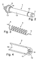
- FIGS. 2 to 4 show the role tensioning device in disassembled state. It shows FIG. 2 the carrier axis 1, FIG. 3 the preferred embodiment of the biasing device as a tension spring 3 and FIG. 4 the sleeve 2.
- carrier axis has a lateral surface 15 over which the tension spring 3 is slipped.
- the tension spring 3 is preferably designed as a torsion spring.
- the tension spring 3 at its ends spring legs 4, 5.
- One of the spring legs 4 protrudes into an opening 14 of the carrier axis 1 and is held in this way in position.
- the tension spring 3 is preferably constructed symmetrically and the spring legs 4, 5 are preferably of equal length.
- the opening 14 in the lateral surface 15 of the carrier axis 1 is preferably formed as a bore in a guide surface 13 of the carrier axis 1, wherein the guide surface 13 is formed as part of the lateral surface 15 of the carrier axis 1 with an enlarged diameter.
- one end of the sleeve 2 is mounted on this guide surface 13.
- the sleeve 2 surrounds the tension spring 3 and the carrier axis 1.
- On the outer circumferential surface of the sleeve 2 is a roller 17 of a medium to be printed on. The coefficient of friction between the outer circumferential surface of the sleeve 2 and the inner circumferential surface of the roller 17 is adjusted so that the roller 17 slides on the sleeve 2 as soon as the sleeve 2 is blocked by the tension spring 3.
- the sleeve 2 biases the tension spring 3, in which the tension spring 3 is fixed to the sleeve 2 at one end, which is preferably designed as a second spring leg 5, so that the sleeve 2 can be rotated about the longitudinal axis of the carrier axis 1 by an angle ⁇ .
- the tension spring 3 is tensioned during a rotation of the sleeve 2.
- the sleeve 2 is shown in detail in a sectional drawing. It has, in addition to a lateral surface 16 at least one opening 9, preferably there are four openings 9.
- This opening 9 is preferably formed as a recess on the inside of the lateral surface 16 of the sleeve 2. In this recess, the spring leg 5 can be clamped, so that the tension spring 3 is tensioned during a rotational movement of the sleeve 2.
- the opening 9 is formed in the lateral surface 16 of the sleeve 2 as an axially extending slot in the sleeve lateral surface 16, in which the spring leg 5 rests.
- the spring leg 5 is formed in a straight line and parallel to the longitudinal axis of the support shaft 1 and lies in the axially extending slot 9 in the sleeve lateral surface 16, so that upon a rotational movement of the sleeve 2, which is perpendicular to the slot direction, the tension spring 3 is tensioned.
- the diameter D of the tension spring 3 is formed such that the tension spring in the rest state neither the outer shell surface 15 of the support axis nor the outer surface of the shell 16 touches the shell. This diameter D of the tension spring 3 can be changed by a rotational movement of the sleeve 2 about the longitudinal axis of the carrier axis 1.
- the tension spring 3 is after a rotational movement of the sleeve 2 about the longitudinal axis of the support shaft 1 at an angle ⁇ on the inner surface of the shell sleeve.
- the diameter of the tension spring 3 increases to a maximum diameter D max .
- the tension spring 3 is after a rotational movement of the sleeve 2 about the longitudinal axis of the support axis 1 at an angle ⁇ on the outer surface of the shell of the carrier axis.
- the diameter of the tension spring 3 decreases to a minimum diameter D min .
- the angle of rotation ⁇ or ⁇ , by which the tension spring 3 and the sleeve 2 are rotatable, is preferably between 180 and 450 ° C, more preferably the angle of rotation for both angles ⁇ and ⁇ at 360 ° C, so that by a full revolution the sleeve 2 a roll 17 can be rolled with a medium to be printed by a full revolution.
- a latching groove 10 is provided on the outer shell surface 15 of the support axis 1, in which engages a formed on the inside of the sleeve shell surface 16 locking web 11, so that the sleeve 2 on the support shaft 1 is axially immovable , However, is locked rotatably about the support axis 1.
- a reverse arrangement that is, that the locking groove on the sleeve 2 and the locking ridge on the support shaft 1 is arranged, is also conceivable.
- the latching web 11 on the sleeve 2 is surrounded by guide surfaces 12 which rest directly on the outer shell surface 15 of the support shaft 1.
- the outer shell surface 16 of the sleeve 2 is formed as a friction surface and frictionally connected to an inner circumferential surface of the roller 17 with medium to be printed. This frictional connection is maintained during a movement of the roller 17 with the sleeve 2 as long as the sleeve 2 can rotate with the roller 17, that is, as long as the sleeve 2 is not affected by the concern of the tension spring 3 either on the inner shell surface 16 of the sleeve 2 or the outer shell surface 15 of the support shaft 1 is applied and thus blocks the rotational movement of the sleeve 2.
- FIG. 6 shows such a role of a medium to be printed, preferably a paper roll 17 which is fixed to a roller carrier housing 18, wherein the determination of the role by the rotationally fixed carrier axis 1 takes place.
- the roller tensioning device for example, in a printer ensures that the roller 17 rests after a printing operation with a certain voltage in the roller carrier housing 18.
- the roller 17 is driven on the sleeve 2 by the action of an external force on the roller 17, wherein the sleeve 2 rotates with the roller 17 and thereby the tension spring 3 is tensioned.
- the roller 17 is further rotated by the action of external force on the roller 17, wherein the roller core slides on the outer surface of the shell 2 shell. If the feed of the medium to be printed is stopped, the force of the external force on the roller 17 is adjusted. Subsequently, the restoring force of the tension spring causes 3, that the roller 17 in a direction opposite to the outer driving force reverses direction by an angle ⁇ , wherein the sleeve 2 rotates with the roller 17.
Landscapes
- Unwinding Webs (AREA)
- Accessory Devices And Overall Control Thereof (AREA)
Applications Claiming Priority (1)
| Application Number | Priority Date | Filing Date | Title |
|---|---|---|---|
| DE102008020078A DE102008020078A1 (de) | 2008-04-22 | 2008-04-22 | Rollenspannvorrichtung, Drucker und Verfahren zum Spannen einer Rolle |
Publications (3)
| Publication Number | Publication Date |
|---|---|
| EP2112105A2 true EP2112105A2 (fr) | 2009-10-28 |
| EP2112105A3 EP2112105A3 (fr) | 2011-03-02 |
| EP2112105B1 EP2112105B1 (fr) | 2012-02-08 |
Family
ID=40897402
Family Applications (1)
| Application Number | Title | Priority Date | Filing Date |
|---|---|---|---|
| EP09003649A Active EP2112105B1 (fr) | 2008-04-22 | 2009-03-13 | Dispositif de tension de rouleaux, imprimante et procédé destiné à tendre un rouleau |
Country Status (3)
| Country | Link |
|---|---|
| EP (1) | EP2112105B1 (fr) |
| AT (1) | ATE544711T1 (fr) |
| DE (1) | DE102008020078A1 (fr) |
Cited By (5)
| Publication number | Priority date | Publication date | Assignee | Title |
|---|---|---|---|---|
| ITFI20110182A1 (it) * | 2011-08-16 | 2013-02-17 | Co Me Sa S R L | Dispositivo per il tensionamento di nastri di materiale plastico per l'alimentazione di macchine per la produzione di imballaggi protettivi a cuscini di aria. |
| WO2014049626A1 (fr) * | 2012-09-27 | 2014-04-03 | Sefra Italia S.R.L. | Système constructif concernant un dispositif à rouleau pour dérouler/enrouler et mettre sous tension une bande flexible |
| CN104908466A (zh) * | 2015-05-15 | 2015-09-16 | 苏州佳世达光电有限公司 | 一种张紧装置及标签打印机 |
| CN110589542A (zh) * | 2019-10-15 | 2019-12-20 | 宁波经纬数控设备有限公司 | 一种卷材送料设备及图文机 |
| CN114408321A (zh) * | 2022-01-25 | 2022-04-29 | 莱州市同力机械有限公司 | 具有张紧作用的收标辊 |
Family Cites Families (3)
| Publication number | Priority date | Publication date | Assignee | Title |
|---|---|---|---|---|
| FR2630420B1 (fr) * | 1988-04-25 | 1990-10-12 | Aerospatiale | Cassette d'emmagasinage et de distribution de fil ou ruban sous tension prereglee, utilisable notamment sur une machine pour realiser des pieces creuses par enroulement filamentaire |
| JP2803612B2 (ja) * | 1995-12-19 | 1998-09-24 | ノーリツ鋼機株式会社 | ペーパマガジン |
| US7014139B2 (en) * | 2003-04-17 | 2006-03-21 | Brady Worldwide, Inc. | Unwind spool assembly |
-
2008
- 2008-04-22 DE DE102008020078A patent/DE102008020078A1/de not_active Withdrawn
-
2009
- 2009-03-13 EP EP09003649A patent/EP2112105B1/fr active Active
- 2009-03-13 AT AT09003649T patent/ATE544711T1/de active
Non-Patent Citations (1)
| Title |
|---|
| None |
Cited By (7)
| Publication number | Priority date | Publication date | Assignee | Title |
|---|---|---|---|---|
| ITFI20110182A1 (it) * | 2011-08-16 | 2013-02-17 | Co Me Sa S R L | Dispositivo per il tensionamento di nastri di materiale plastico per l'alimentazione di macchine per la produzione di imballaggi protettivi a cuscini di aria. |
| WO2014049626A1 (fr) * | 2012-09-27 | 2014-04-03 | Sefra Italia S.R.L. | Système constructif concernant un dispositif à rouleau pour dérouler/enrouler et mettre sous tension une bande flexible |
| CN104908466A (zh) * | 2015-05-15 | 2015-09-16 | 苏州佳世达光电有限公司 | 一种张紧装置及标签打印机 |
| CN104908466B (zh) * | 2015-05-15 | 2017-07-21 | 苏州佳世达光电有限公司 | 一种张紧装置及标签打印机 |
| CN110589542A (zh) * | 2019-10-15 | 2019-12-20 | 宁波经纬数控设备有限公司 | 一种卷材送料设备及图文机 |
| CN114408321A (zh) * | 2022-01-25 | 2022-04-29 | 莱州市同力机械有限公司 | 具有张紧作用的收标辊 |
| CN114408321B (zh) * | 2022-01-25 | 2023-09-26 | 莱州市同力机械有限公司 | 具有张紧作用的收标辊 |
Also Published As
| Publication number | Publication date |
|---|---|
| EP2112105A3 (fr) | 2011-03-02 |
| ATE544711T1 (de) | 2012-02-15 |
| DE102008020078A1 (de) | 2009-10-29 |
| EP2112105B1 (fr) | 2012-02-08 |
Similar Documents
| Publication | Publication Date | Title |
|---|---|---|
| DE68914769T2 (de) | Vorrichtung zum Regeln der Schneidelänge. | |
| DE3023893C2 (fr) | ||
| EP2112105B1 (fr) | Dispositif de tension de rouleaux, imprimante et procédé destiné à tendre un rouleau | |
| WO1997028075A1 (fr) | Rouleau pour enrouleur | |
| EP2149530A1 (fr) | Plieuse | |
| DE3347178A1 (de) | Papierblatt-ausgabevorrichtung | |
| DE69703620T2 (de) | Elastische mittel zum aufrollen eines rollvorhangs | |
| EP1316524B1 (fr) | Arbre d'enroulement avec accouplement à friction | |
| DE60209076T2 (de) | Reibungskupplung zur Energieübertragung mit begrenztem Drehmoment zwischen zwei Rollen eines Hangerätes | |
| DE4403176C2 (de) | Papiertuchspender | |
| DE2421393A1 (de) | Vorrichtung zum festspannen eines hohldornes auf einer antriebswelle | |
| DE102007010733B4 (de) | Einspannvorrichtung für eine Materialbahn | |
| DE3704991C2 (fr) | ||
| EP0652176A1 (fr) | Dispositif d'enroulage pour les structures flexibles et planes ainsi que la méthode d'enroulement des structures flexibles et planes | |
| DE102016103197A1 (de) | Riemengetriebe und lenksystem | |
| EP2042461B1 (fr) | Support de noyau autobloquant | |
| EP0463997B1 (fr) | Cassette pour l'enroulement de matériau photographique en bande | |
| DE102008043310A1 (de) | Breitstreckeinrichtung | |
| EP0234589B1 (fr) | Dispositif d'alimentation en papier pour imprimantes | |
| DE60005658T2 (de) | Medienführungsglied | |
| DE1921344A1 (de) | Kerneinspannvorrichtung | |
| DE2060136A1 (de) | Angelschnurrolle | |
| DE102005037647A1 (de) | Vorrichtung zur Herstellung und/oder Behandlung einer Materialbahn, insbesondere Papier- oder Kartonbahn | |
| DE60312668T2 (de) | Umwickelarm für plastikfolienlängsschneidvorrichtung | |
| DE2753524A1 (de) | Vorrichtung zum haltern eines wickelkerns an einer welle |
Legal Events
| Date | Code | Title | Description |
|---|---|---|---|
| PUAI | Public reference made under article 153(3) epc to a published international application that has entered the european phase |
Free format text: ORIGINAL CODE: 0009012 |
|
| AK | Designated contracting states |
Kind code of ref document: A2 Designated state(s): AT BE BG CH CY CZ DE DK EE ES FI FR GB GR HR HU IE IS IT LI LT LU LV MC MK MT NL NO PL PT RO SE SI SK TR |
|
| AX | Request for extension of the european patent |
Extension state: AL BA RS |
|
| PUAL | Search report despatched |
Free format text: ORIGINAL CODE: 0009013 |
|
| AK | Designated contracting states |
Kind code of ref document: A3 Designated state(s): AT BE BG CH CY CZ DE DK EE ES FI FR GB GR HR HU IE IS IT LI LT LU LV MC MK MT NL NO PL PT RO SE SI SK TR |
|
| AX | Request for extension of the european patent |
Extension state: AL BA RS |
|
| RIC1 | Information provided on ipc code assigned before grant |
Ipc: B65H 23/06 20060101AFI20110126BHEP |
|
| 17P | Request for examination filed |
Effective date: 20110603 |
|
| GRAP | Despatch of communication of intention to grant a patent |
Free format text: ORIGINAL CODE: EPIDOSNIGR1 |
|
| AKX | Designation fees paid |
Designated state(s): AT BE BG CH CY CZ DE DK EE ES FI FR GB GR HR HU IE IS IT LI LT LU LV MC MK MT NL NO PL PT RO SE SI SK TR |
|
| GRAS | Grant fee paid |
Free format text: ORIGINAL CODE: EPIDOSNIGR3 |
|
| GRAA | (expected) grant |
Free format text: ORIGINAL CODE: 0009210 |
|
| AK | Designated contracting states |
Kind code of ref document: B1 Designated state(s): AT BE BG CH CY CZ DE DK EE ES FI FR GB GR HR HU IE IS IT LI LT LU LV MC MK MT NL NO PL PT RO SE SI SK TR |
|
| REG | Reference to a national code |
Ref country code: GB Ref legal event code: FG4D Free format text: NOT ENGLISH |
|
| REG | Reference to a national code |
Ref country code: AT Ref legal event code: REF Ref document number: 544711 Country of ref document: AT Kind code of ref document: T Effective date: 20120215 Ref country code: CH Ref legal event code: EP |
|
| REG | Reference to a national code |
Ref country code: DE Ref legal event code: R096 Ref document number: 502009002664 Country of ref document: DE Effective date: 20120405 |
|
| REG | Reference to a national code |
Ref country code: NL Ref legal event code: VDEP Effective date: 20120208 |
|
| LTIE | Lt: invalidation of european patent or patent extension |
Effective date: 20120208 |
|
| PG25 | Lapsed in a contracting state [announced via postgrant information from national office to epo] |
Ref country code: HR Free format text: LAPSE BECAUSE OF FAILURE TO SUBMIT A TRANSLATION OF THE DESCRIPTION OR TO PAY THE FEE WITHIN THE PRESCRIBED TIME-LIMIT Effective date: 20120208 Ref country code: NO Free format text: LAPSE BECAUSE OF FAILURE TO SUBMIT A TRANSLATION OF THE DESCRIPTION OR TO PAY THE FEE WITHIN THE PRESCRIBED TIME-LIMIT Effective date: 20120508 Ref country code: LT Free format text: LAPSE BECAUSE OF FAILURE TO SUBMIT A TRANSLATION OF THE DESCRIPTION OR TO PAY THE FEE WITHIN THE PRESCRIBED TIME-LIMIT Effective date: 20120208 Ref country code: NL Free format text: LAPSE BECAUSE OF FAILURE TO SUBMIT A TRANSLATION OF THE DESCRIPTION OR TO PAY THE FEE WITHIN THE PRESCRIBED TIME-LIMIT Effective date: 20120208 Ref country code: IS Free format text: LAPSE BECAUSE OF FAILURE TO SUBMIT A TRANSLATION OF THE DESCRIPTION OR TO PAY THE FEE WITHIN THE PRESCRIBED TIME-LIMIT Effective date: 20120608 |
|
| REG | Reference to a national code |
Ref country code: IE Ref legal event code: FD4D |
|
| PG25 | Lapsed in a contracting state [announced via postgrant information from national office to epo] |
Ref country code: PT Free format text: LAPSE BECAUSE OF FAILURE TO SUBMIT A TRANSLATION OF THE DESCRIPTION OR TO PAY THE FEE WITHIN THE PRESCRIBED TIME-LIMIT Effective date: 20120608 Ref country code: LV Free format text: LAPSE BECAUSE OF FAILURE TO SUBMIT A TRANSLATION OF THE DESCRIPTION OR TO PAY THE FEE WITHIN THE PRESCRIBED TIME-LIMIT Effective date: 20120208 Ref country code: PL Free format text: LAPSE BECAUSE OF FAILURE TO SUBMIT A TRANSLATION OF THE DESCRIPTION OR TO PAY THE FEE WITHIN THE PRESCRIBED TIME-LIMIT Effective date: 20120208 Ref country code: FI Free format text: LAPSE BECAUSE OF FAILURE TO SUBMIT A TRANSLATION OF THE DESCRIPTION OR TO PAY THE FEE WITHIN THE PRESCRIBED TIME-LIMIT Effective date: 20120208 Ref country code: GR Free format text: LAPSE BECAUSE OF FAILURE TO SUBMIT A TRANSLATION OF THE DESCRIPTION OR TO PAY THE FEE WITHIN THE PRESCRIBED TIME-LIMIT Effective date: 20120509 |
|
| PG25 | Lapsed in a contracting state [announced via postgrant information from national office to epo] |
Ref country code: CY Free format text: LAPSE BECAUSE OF FAILURE TO SUBMIT A TRANSLATION OF THE DESCRIPTION OR TO PAY THE FEE WITHIN THE PRESCRIBED TIME-LIMIT Effective date: 20120208 |
|
| BERE | Be: lapsed |
Owner name: WINCOR NIXDORF INTERNATIONAL G.M.B.H. Effective date: 20120331 |
|
| PG25 | Lapsed in a contracting state [announced via postgrant information from national office to epo] |
Ref country code: EE Free format text: LAPSE BECAUSE OF FAILURE TO SUBMIT A TRANSLATION OF THE DESCRIPTION OR TO PAY THE FEE WITHIN THE PRESCRIBED TIME-LIMIT Effective date: 20120208 Ref country code: RO Free format text: LAPSE BECAUSE OF FAILURE TO SUBMIT A TRANSLATION OF THE DESCRIPTION OR TO PAY THE FEE WITHIN THE PRESCRIBED TIME-LIMIT Effective date: 20120208 Ref country code: SI Free format text: LAPSE BECAUSE OF FAILURE TO SUBMIT A TRANSLATION OF THE DESCRIPTION OR TO PAY THE FEE WITHIN THE PRESCRIBED TIME-LIMIT Effective date: 20120208 Ref country code: SE Free format text: LAPSE BECAUSE OF FAILURE TO SUBMIT A TRANSLATION OF THE DESCRIPTION OR TO PAY THE FEE WITHIN THE PRESCRIBED TIME-LIMIT Effective date: 20120208 Ref country code: IE Free format text: LAPSE BECAUSE OF FAILURE TO SUBMIT A TRANSLATION OF THE DESCRIPTION OR TO PAY THE FEE WITHIN THE PRESCRIBED TIME-LIMIT Effective date: 20120208 Ref country code: DK Free format text: LAPSE BECAUSE OF FAILURE TO SUBMIT A TRANSLATION OF THE DESCRIPTION OR TO PAY THE FEE WITHIN THE PRESCRIBED TIME-LIMIT Effective date: 20120208 Ref country code: MC Free format text: LAPSE BECAUSE OF NON-PAYMENT OF DUE FEES Effective date: 20120331 Ref country code: CZ Free format text: LAPSE BECAUSE OF FAILURE TO SUBMIT A TRANSLATION OF THE DESCRIPTION OR TO PAY THE FEE WITHIN THE PRESCRIBED TIME-LIMIT Effective date: 20120208 |
|
| PG25 | Lapsed in a contracting state [announced via postgrant information from national office to epo] |
Ref country code: IT Free format text: LAPSE BECAUSE OF FAILURE TO SUBMIT A TRANSLATION OF THE DESCRIPTION OR TO PAY THE FEE WITHIN THE PRESCRIBED TIME-LIMIT Effective date: 20120208 Ref country code: SK Free format text: LAPSE BECAUSE OF FAILURE TO SUBMIT A TRANSLATION OF THE DESCRIPTION OR TO PAY THE FEE WITHIN THE PRESCRIBED TIME-LIMIT Effective date: 20120208 |
|
| PLBE | No opposition filed within time limit |
Free format text: ORIGINAL CODE: 0009261 |
|
| STAA | Information on the status of an ep patent application or granted ep patent |
Free format text: STATUS: NO OPPOSITION FILED WITHIN TIME LIMIT |
|
| 26N | No opposition filed |
Effective date: 20121109 |
|
| PG25 | Lapsed in a contracting state [announced via postgrant information from national office to epo] |
Ref country code: BE Free format text: LAPSE BECAUSE OF NON-PAYMENT OF DUE FEES Effective date: 20120331 |
|
| PG25 | Lapsed in a contracting state [announced via postgrant information from national office to epo] |
Ref country code: MK Free format text: LAPSE BECAUSE OF FAILURE TO SUBMIT A TRANSLATION OF THE DESCRIPTION OR TO PAY THE FEE WITHIN THE PRESCRIBED TIME-LIMIT Effective date: 20120208 |
|
| REG | Reference to a national code |
Ref country code: DE Ref legal event code: R097 Ref document number: 502009002664 Country of ref document: DE Effective date: 20121109 |
|
| PG25 | Lapsed in a contracting state [announced via postgrant information from national office to epo] |
Ref country code: ES Free format text: LAPSE BECAUSE OF FAILURE TO SUBMIT A TRANSLATION OF THE DESCRIPTION OR TO PAY THE FEE WITHIN THE PRESCRIBED TIME-LIMIT Effective date: 20120519 |
|
| PG25 | Lapsed in a contracting state [announced via postgrant information from national office to epo] |
Ref country code: BG Free format text: LAPSE BECAUSE OF FAILURE TO SUBMIT A TRANSLATION OF THE DESCRIPTION OR TO PAY THE FEE WITHIN THE PRESCRIBED TIME-LIMIT Effective date: 20120508 Ref country code: MT Free format text: LAPSE BECAUSE OF FAILURE TO SUBMIT A TRANSLATION OF THE DESCRIPTION OR TO PAY THE FEE WITHIN THE PRESCRIBED TIME-LIMIT Effective date: 20120208 |
|
| REG | Reference to a national code |
Ref country code: CH Ref legal event code: PL |
|
| PG25 | Lapsed in a contracting state [announced via postgrant information from national office to epo] |
Ref country code: LI Free format text: LAPSE BECAUSE OF NON-PAYMENT OF DUE FEES Effective date: 20130331 Ref country code: CH Free format text: LAPSE BECAUSE OF NON-PAYMENT OF DUE FEES Effective date: 20130331 |
|
| PG25 | Lapsed in a contracting state [announced via postgrant information from national office to epo] |
Ref country code: TR Free format text: LAPSE BECAUSE OF FAILURE TO SUBMIT A TRANSLATION OF THE DESCRIPTION OR TO PAY THE FEE WITHIN THE PRESCRIBED TIME-LIMIT Effective date: 20120208 |
|
| PG25 | Lapsed in a contracting state [announced via postgrant information from national office to epo] |
Ref country code: LU Free format text: LAPSE BECAUSE OF NON-PAYMENT OF DUE FEES Effective date: 20120313 |
|
| PG25 | Lapsed in a contracting state [announced via postgrant information from national office to epo] |
Ref country code: HU Free format text: LAPSE BECAUSE OF FAILURE TO SUBMIT A TRANSLATION OF THE DESCRIPTION OR TO PAY THE FEE WITHIN THE PRESCRIBED TIME-LIMIT Effective date: 20090313 |
|
| REG | Reference to a national code |
Ref country code: AT Ref legal event code: MM01 Ref document number: 544711 Country of ref document: AT Kind code of ref document: T Effective date: 20140313 |
|
| PG25 | Lapsed in a contracting state [announced via postgrant information from national office to epo] |
Ref country code: AT Free format text: LAPSE BECAUSE OF NON-PAYMENT OF DUE FEES Effective date: 20140313 |
|
| REG | Reference to a national code |
Ref country code: FR Ref legal event code: PLFP Year of fee payment: 8 |
|
| REG | Reference to a national code |
Ref country code: FR Ref legal event code: PLFP Year of fee payment: 9 |
|
| REG | Reference to a national code |
Ref country code: FR Ref legal event code: PLFP Year of fee payment: 10 |
|
| REG | Reference to a national code |
Ref country code: FR Ref legal event code: PLFP Year of fee payment: 15 |
|
| REG | Reference to a national code |
Ref country code: GB Ref legal event code: 732E Free format text: REGISTERED BETWEEN 20230316 AND 20230322 |
|
| REG | Reference to a national code |
Ref country code: GB Ref legal event code: 732E Free format text: REGISTERED BETWEEN 20230525 AND 20230601 |
|
| REG | Reference to a national code |
Ref country code: DE Ref legal event code: R081 Ref document number: 502009002664 Country of ref document: DE Owner name: DIEBOLD NIXDORF SYSTEMS GMBH, DE Free format text: FORMER OWNER: WINCOR NIXDORF INTERNATIONAL GMBH, 33106 PADERBORN, DE |
|
| PGFP | Annual fee paid to national office [announced via postgrant information from national office to epo] |
Ref country code: DE Payment date: 20250218 Year of fee payment: 17 |
|
| PGFP | Annual fee paid to national office [announced via postgrant information from national office to epo] |
Ref country code: FR Payment date: 20250218 Year of fee payment: 17 |
|
| PGFP | Annual fee paid to national office [announced via postgrant information from national office to epo] |
Ref country code: GB Payment date: 20250221 Year of fee payment: 17 |