EP2112277A2 - Erdbaumaschine und Ladeschaufel für eine solche Erdbaumaschine - Google Patents
Erdbaumaschine und Ladeschaufel für eine solche Erdbaumaschine Download PDFInfo
- Publication number
- EP2112277A2 EP2112277A2 EP09305318A EP09305318A EP2112277A2 EP 2112277 A2 EP2112277 A2 EP 2112277A2 EP 09305318 A EP09305318 A EP 09305318A EP 09305318 A EP09305318 A EP 09305318A EP 2112277 A2 EP2112277 A2 EP 2112277A2
- Authority
- EP
- European Patent Office
- Prior art keywords
- bucket
- articulated arm
- support device
- earthmoving machine
- loading
- Prior art date
- Legal status (The legal status is an assumption and is not a legal conclusion. Google has not performed a legal analysis and makes no representation as to the accuracy of the status listed.)
- Granted
Links
Images



Classifications
-
- E—FIXED CONSTRUCTIONS
- E02—HYDRAULIC ENGINEERING; FOUNDATIONS; SOIL SHIFTING
- E02F—DREDGING; SOIL-SHIFTING
- E02F3/00—Dredgers; Soil-shifting machines
- E02F3/04—Dredgers; Soil-shifting machines mechanically-driven
- E02F3/28—Dredgers; Soil-shifting machines mechanically-driven with digging tools mounted on a dipper- or bucket-arm, i.e. there is either one arm or a pair of arms, e.g. dippers, buckets
- E02F3/30—Dredgers; Soil-shifting machines mechanically-driven with digging tools mounted on a dipper- or bucket-arm, i.e. there is either one arm or a pair of arms, e.g. dippers, buckets with a dipper-arm pivoted on a cantilever beam, i.e. boom
- E02F3/307—Dredgers; Soil-shifting machines mechanically-driven with digging tools mounted on a dipper- or bucket-arm, i.e. there is either one arm or a pair of arms, e.g. dippers, buckets with a dipper-arm pivoted on a cantilever beam, i.e. boom the boom and the dipper-arm being connected so as to permit relative movement in more than one plane
-
- E—FIXED CONSTRUCTIONS
- E02—HYDRAULIC ENGINEERING; FOUNDATIONS; SOIL SHIFTING
- E02F—DREDGING; SOIL-SHIFTING
- E02F3/00—Dredgers; Soil-shifting machines
- E02F3/04—Dredgers; Soil-shifting machines mechanically-driven
- E02F3/28—Dredgers; Soil-shifting machines mechanically-driven with digging tools mounted on a dipper- or bucket-arm, i.e. there is either one arm or a pair of arms, e.g. dippers, buckets
- E02F3/30—Dredgers; Soil-shifting machines mechanically-driven with digging tools mounted on a dipper- or bucket-arm, i.e. there is either one arm or a pair of arms, e.g. dippers, buckets with a dipper-arm pivoted on a cantilever beam, i.e. boom
- E02F3/301—Dredgers; Soil-shifting machines mechanically-driven with digging tools mounted on a dipper- or bucket-arm, i.e. there is either one arm or a pair of arms, e.g. dippers, buckets with a dipper-arm pivoted on a cantilever beam, i.e. boom with more than two arms (boom included), e.g. two-part boom with additional dipper-arm
-
- E—FIXED CONSTRUCTIONS
- E02—HYDRAULIC ENGINEERING; FOUNDATIONS; SOIL SHIFTING
- E02F—DREDGING; SOIL-SHIFTING
- E02F3/00—Dredgers; Soil-shifting machines
- E02F3/04—Dredgers; Soil-shifting machines mechanically-driven
- E02F3/28—Dredgers; Soil-shifting machines mechanically-driven with digging tools mounted on a dipper- or bucket-arm, i.e. there is either one arm or a pair of arms, e.g. dippers, buckets
- E02F3/30—Dredgers; Soil-shifting machines mechanically-driven with digging tools mounted on a dipper- or bucket-arm, i.e. there is either one arm or a pair of arms, e.g. dippers, buckets with a dipper-arm pivoted on a cantilever beam, i.e. boom
- E02F3/308—Dredgers; Soil-shifting machines mechanically-driven with digging tools mounted on a dipper- or bucket-arm, i.e. there is either one arm or a pair of arms, e.g. dippers, buckets with a dipper-arm pivoted on a cantilever beam, i.e. boom working outwardly
-
- E—FIXED CONSTRUCTIONS
- E02—HYDRAULIC ENGINEERING; FOUNDATIONS; SOIL SHIFTING
- E02F—DREDGING; SOIL-SHIFTING
- E02F3/00—Dredgers; Soil-shifting machines
- E02F3/04—Dredgers; Soil-shifting machines mechanically-driven
- E02F3/28—Dredgers; Soil-shifting machines mechanically-driven with digging tools mounted on a dipper- or bucket-arm, i.e. there is either one arm or a pair of arms, e.g. dippers, buckets
- E02F3/34—Dredgers; Soil-shifting machines mechanically-driven with digging tools mounted on a dipper- or bucket-arm, i.e. there is either one arm or a pair of arms, e.g. dippers, buckets with bucket-arms, i.e. a pair of arms, e.g. manufacturing processes, form, geometry, material of bucket-arms directly pivoted on the frames of tractors or self-propelled machines
- E02F3/352—Buckets movable along a fixed guide
-
- E—FIXED CONSTRUCTIONS
- E02—HYDRAULIC ENGINEERING; FOUNDATIONS; SOIL SHIFTING
- E02F—DREDGING; SOIL-SHIFTING
- E02F3/00—Dredgers; Soil-shifting machines
- E02F3/04—Dredgers; Soil-shifting machines mechanically-driven
- E02F3/96—Dredgers; Soil-shifting machines mechanically-driven with arrangements for alternate or simultaneous use of different digging elements
- E02F3/961—Dredgers; Soil-shifting machines mechanically-driven with arrangements for alternate or simultaneous use of different digging elements with several digging elements or tools mounted on one machine
-
- E—FIXED CONSTRUCTIONS
- E02—HYDRAULIC ENGINEERING; FOUNDATIONS; SOIL SHIFTING
- E02F—DREDGING; SOIL-SHIFTING
- E02F9/00—Component parts of dredgers or soil-shifting machines, not restricted to one of the kinds covered by groups E02F3/00 - E02F7/00
- E02F9/08—Superstructures; Supports for superstructures
- E02F9/085—Ground-engaging fitting for supporting the machines while working, e.g. outriggers, legs
Definitions
- the present invention relates to the field of public works. More specifically, it relates to an earthmoving machine such as a loader-excavator, as well as a loading bucket for such an earthmoving machine.
- a conventional loader comprises a self-propelled frame and a front loading bucket, supported by one or more rigid arms and articulated to this self-propelled frame.
- An excavator is used to dig into the ground. It conventionally comprises an articulated arm for maneuvering a toothed tool designed to be driven into the ground and dismember it.
- An excavator can be designed so that it can also be used as a loader. It is then a loader-excavator whose articulated arm can be equipped, with the choice, of a digging tool or a bucket of loading. Such a bucket is loaded by being pushed on the ground, forwards, in the material to be picked up. The thrust then exerted on the loading bucket to advance it results from a displacement of the loader-excavator itself and it is transmitted by the articulated arm which, therefore, can be subjected to multiple efforts. In particular, this articulated arm can be biased when the pushed bucket encounters a resistance near only one of its two lateral ends.
- the articulated arm While it can therefore be subjected to very high value twists, the articulated arm must have a reasonable mass, especially in order to be able to easily maneuver a digging tool.
- the problem resulting from the fact that the articulated arm can be subjected to high torsion is even more acute when the articulated arm is offset laterally, insofar as this results in an increase in the lever arm of the left or right side of the bucket. loading, relative to the hinge area of this bucket on the articulated arm.
- the invention is at least intended to improve the ability of an earthmoving machine to exert a thrust on a loading bucket fitted to this machine.
- an earthmover comprising a chassis carried by a rolling assembly, as well as an articulated arm for supporting and operating a tool such as a loading bucket.
- This earthmoving machine also comprises at least one support device for a loading bucket in a low pickup position. Through this support device, the chassis is able to exert a thrust on the loading bucket in a direction of movement of the earthmover, when the articulated arm holds the bucket in the low position of pickup.
- an earthmoving machine can be designed so as to be able to exert many strong thrusts on a bucket, without that ensues a malfunction or premature wear of the support arm of this bucket.
- the loading bucket is a tool that can be mounted on the articulated arm via a tool holder and that is part of a work head articulated to this arm. It will be noted that the invention has the advantage of being compatible with proven and effective architectures for coupling the working head to the actuating actuator of this working head around its tilting axis.
- this machine comprises a second support device through which the chassis can exert a thrust on a loading bucket, in said direction of movement, when the articulated arm holds this bucket in the low position of pickup, the one and the other support device being offset horizontally from one another.
- the one and the other support device are positioned in such a way that, when it holds the bucket in the lower pickup position, the articulated arm is located between these two support devices so that be that little or no stress in torsion when loading the bucket by moving the bucket on the ground.
- the earth-moving machine is more precisely a loader-excavator which comprises a reversible coupling tool holder of a tool at a distal end of said articulated arm, that is to say at the furthest end of the chassis, and of which this articulated arm comprises a succession of several tilting segments in substantially vertical planes.
- the tilting segments of the articulated arm comprise a distal segment and several other tilting segments, each of which is movable between first and second end-of-travel positions such that, when each of these several other tilting segments is immobilized in its first end position stroke, the low bucket loading position is reached by only tilting the distal segment around a proximal end of this distal segment.
- the machine comprises a joint between a distal end of the articulated arm and the bucket carried by this articulated arm, the support device defining a substantially horizontal alignment axis with which the axis of said articulation substantially coincides, when the articulated arm holds the bucket in said lower pickup position, and around which the bucket tilts while resting on the support device when the axis of the joint and the alignment axis coincide.
- the support device comprises a bearing surface of the bucket in its low collector position, this bearing surface having a concavity which has a constant radius of curvature and centered on said alignment axis.
- the support device comprises a guide slot pierced in the bearing surface.
- the support device comprises a scraping transverse blade movable between a low scraping position and a high position in which the bucket can come into abutment against the support device by placing itself in its low collection position, said surface bearing at a front face of the transverse scraping blade.
- the support device comprises a support shoe and a hinge whose axis of rotation forms said alignment axis and through which the shoe is hinged so as to tilt about this axis of rotation.
- said shoe is constituted by the foot of a stabilizer and is movable between a low support position of a portion of the earthmover and a high position in which the bucket can come into abutment against this shoe by placing itself in its low pickup position.
- the earthmoving machine comprises a loading bucket that carries said articulated arm, this articulated arm being able to bring the bucket into a position where the bucket is resting on the support device and which is said low position pickup.
- the invention also relates to a loading bucket for a earthmoving machine.
- This bucket comprises at least one pusher for receiving a thrust from the rear and transmission of this thrust generally in a direction of movement corresponding to the advance of the bucket forward for a pickup.
- the pusher comprises a rear rolling device on a bearing surface of the earthmoving machine.
- the rear rolling device comprises two rollers which have respective substantially horizontal axes of rotation and which are angularly offset from one another about a substantially horizontal axis of tilting of the bucket.
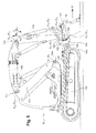
- This excavator-loader 1 comprises a chassis 2 supported by four driving wheels 3.
- This chassis 2 is equipped with a mobile turret 4, which is mounted so as to be pivotable about a vertical axis and which carries a driving cabin 5 and an articulated arm ⁇ 6 for supporting and actuating a tool.
- the articulated arm 6 comprises three tilting segments in substantially vertical planes, that is to say around substantially horizontal axes. These three segments are mounted following each other by being articulated between them. The first of these is referenced 7 and is classically called the arrow. It is connected to the turret 4 by a hinge 8, so as to tilt about a substantially horizontal axis X 1 -X ' 1 .
- the other two segments of the articulated arm 6 are the counter-arrow, referenced 9, and the arm, referenced 10.
- the counter-arrow 9 is connected to the arrow 7 by a hinge 11, so as to be able to tilt relative to the arrow 7, about a substantially horizontal axis X 2 -X ' 2 .
- the counter-boom 9 carries the arm 10, which is connected to it by a hinge 12 so as to be able to tilt about an axis X 3 -X ' 3 substantially horizontal and which is the distal segment of the articulated arm 6.
- the distal end of the arm 10 is provided with a tool holder 14, which is articulated to it by means of a hinge 15 and on which can be mounted reversibly several removable tools of different types.
- the arm 10 carries a cylinder 13 for operating the tool holder 14 around the substantially horizontal axis X 4 -X ' 4 of the articulation 15.
- the coupling device of the tool holder 14 to the cylinder 13 comprises two links articulated to one another, namely a first rod articulated to the arm 10 and a second link articulated to the tool holder 14.
- these two links, a portion of the arm 10 and at least a portion of the tool holder 14 together form a deformable parallelogram on which the cylinder 13 acts to manipulate the tool holder 14 and, more generally, the working head that together form this tool holder and a tool equipping it.
- the tool held by the tool holder 14 is a loading bucket 16 horizontally elongated. Its back, facing back, carries two left and right rear pushers 17, which are laterally offset from one another and which project in a direction inclined towards the rear. The pushers 17 protrude towards the rear of the back of the bucket 16.
- the excavator-loader 1 further comprises two left and right stabilizers 18, each of which is articulated to the frame 2 so that it can be operated by a jack 19 between two positions.
- One of these two positions is that of Figures 1 to 3 , on which each stabilizer 18 forms a support device for the bucket 16.
- these stabilizers 18 are directed towards the ground, in a manner known per se, so as to be able to bear on this ground.
- Each stabilizer 18 comprises a leg 20 and a pivoting shoe 21, which is articulated at the distal end of this leg by means of a hinge 22 and which more precisely forms a foot of the stabilizer 18.
- a tool other than the loading bucket 16 may be mounted on the tool holder 14.
- it may be a digging bucket, narrower than the bucket 16 and mounted so that its back is generally rotated to the top.
- the articulated arm 6 performs complex movements during which each of its segments 7, 9 and 10 tilts around its proximal end.
- the loader-excavator 1 When its articulated arm 6 is provided with the loading bucket 7, the loader-excavator 1 is intended to function as a loader.
- the joints 8 and 11 are fixed, since only the arm 10 is maneuvered.
- the arrow 7 and the counter-arrow 9 form a fixed subset.
- the arrow 7 is then immobilized in one of its two extreme positions or end positions, in which she is in abutment. It is the same with the counter-arrow 9.
- the configuration of the fixed subassembly of the articulated arm 6 is easily reached by placing the arrow 7 and the counter-arrow 9 in abutment .
- the arm 10 can move the loading bucket 16 between an upper discharge position and a lower pickup position, which is that of the Figures 1 to 3 and in which the pushers 17 are supported on the lower faces of the shoes 21 as long as the latter are in their high position.
- the loader-excavator 1 When the loader-excavator 1 is in its configuration of Figures 1 to 3 its bucket 16 can be filled by scraping on the ground. To do this, the loader-excavator 1 is moved forward in the direction of advance symbolized by the arrow A, so that the bucket 6 is driven forwards, on the ground, in the material to load. During this, the chassis 2 transmits its movement to the bucket 16 not only via the articulated arm 6 . Indeed, it also exerts a thrust via the stabilizers 18, which then form support devices for the bucket 16. The pushers 17 receive this thrust and transmit it to the back of the bucket 16.
- the articulated arm 6 is not stressed during the pickup phase. In particular, it is not stressed in torsion, even if the cup 16 encounters resistance in the vicinity of one of its two lateral ends.
- the bucket 16 When its filling is completed, the bucket 16 is lifted by the arm 10 which, to do this, tilts up in the direction indicated by the arrow B 1 , while the arrow 7 and the counter-arrow 9 remain immobile relative at the turret 4.
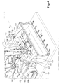
- FIG. 4 On the figure 4 is shown a loader-excavator 101 according to a second embodiment of the invention.
- this excavator-loader 101 is only described as distinguishing it from the excavator-loader 1.
- a reference used hereinafter to refer to a similar or equivalent portion of the loader-excavator 101 a referenced part of the loader-excavator 1 is built by increasing by 100 the reference designating this part in the loader-excavator 1.
- the references of the articulated arm 106, the arrow 107, the hinge 108, the counter-boom 109, the arm 110, the joints 111, 112 and 115 of the excavator-loader 101 are obtained in particular the references of the articulated arm 106, the arrow 107, the hinge 108, the counter-boom 109, the arm 110, the joints 111, 112 and 115 of the excavator-loader 101.
- the frame 102 of the excavator-loader 101 is supported by a roller assembly which includes two side tracks 103 instead of the four wheels 3.
- This frame 102 is not provided with a stabilizer. However, it is equipped with a scraping assembly which comprises a front blade 150 carried by a tilting support 151.
- This support 151 is articulated to the frame 102 so that the blade 150 can be operated by a cylinder 119 between a low position of scraping and a high position which is that of Figures 4 to 6 .
- the front face 152 of the blade 150 forms a transversely elongate concavity. At this concavity, the front face 152 carries two plates 153, each of which is pierced with a generally vertical guide slot 154.
- each pusher 117 is provided with a rolling device which consists of two rollers 155 angularly offset from one another about the axis.
- X 4 -X ' 4 tilting bucket 116 an angle noted ⁇ to the figure 6 .
- the front face of each plate 153 forms a running surface 156 for a pair of rollers 155, each of which has a substantially horizontal axis of rotation X 6 -X ' 6 .
- the running surfaces 156 form a concavity facing forward.
- the rolling surfaces 156 are cylindrical and centered on an alignment axis X 5 -X ' 5 with which the axis X 4 -X' 4 substantially coincides when the bucket 116 is in its low pickup position. Thanks to this, this bucket 116 can tilt around its pivot axis X 4 -X ' 4 while remaining in abutment against the plates 153, which is apparent from a comparison of figures 5 and 6 .
- the rollers 155 roll on the surfaces 156 being guided by the cooperation of the longitudinal edges of the slots 154 with peripheral ribs 157, one team each roller 155.
Landscapes
- Engineering & Computer Science (AREA)
- Mining & Mineral Resources (AREA)
- Civil Engineering (AREA)
- General Engineering & Computer Science (AREA)
- Structural Engineering (AREA)
- Mechanical Engineering (AREA)
- Shovels (AREA)
- Forklifts And Lifting Vehicles (AREA)
- Harvester Elements (AREA)
Applications Claiming Priority (1)
| Application Number | Priority Date | Filing Date | Title |
|---|---|---|---|
| FR0852684A FR2930267B1 (fr) | 2008-04-21 | 2008-04-21 | Engin de terrassement et godet de chargement pour un tel engin de terrassement |
Publications (3)
| Publication Number | Publication Date |
|---|---|
| EP2112277A2 true EP2112277A2 (de) | 2009-10-28 |
| EP2112277A3 EP2112277A3 (de) | 2014-04-30 |
| EP2112277B1 EP2112277B1 (de) | 2016-09-07 |
Family
ID=39816722
Family Applications (1)
| Application Number | Title | Priority Date | Filing Date |
|---|---|---|---|
| EP09305318.9A Active EP2112277B1 (de) | 2008-04-21 | 2009-04-14 | Erdbaumaschine und Ladeschaufel für eine solche Erdbaumaschine |
Country Status (2)
| Country | Link |
|---|---|
| EP (1) | EP2112277B1 (de) |
| FR (1) | FR2930267B1 (de) |
Cited By (1)
| Publication number | Priority date | Publication date | Assignee | Title |
|---|---|---|---|---|
| DE102014000027A1 (de) | 2014-01-04 | 2014-10-30 | Johannes Burde | Teleskopsystem für die Integration in Monoblock- und Verstellausleger für das Verfahren des Stiel- und Hauptlagers |
Citations (1)
| Publication number | Priority date | Publication date | Assignee | Title |
|---|---|---|---|---|
| FR2119625A5 (de) | 1970-12-23 | 1972-08-04 | Sogl Rupert |
Family Cites Families (7)
| Publication number | Priority date | Publication date | Assignee | Title |
|---|---|---|---|---|
| CA669368A (en) * | 1963-08-27 | E. Metailler Roger | Power shovel with jack-controlled bucket inclination | |
| US2502681A (en) * | 1945-03-17 | 1950-04-04 | Unit Crane & Shovel Corp | Material handling apparatus |
| US2548084A (en) * | 1947-09-19 | 1951-04-10 | Eddie B Wagner | Scoop-shovel vehicle |
| US3027662A (en) * | 1958-07-25 | 1962-04-03 | Jr Ernest R Cunningham | Combination motor grader and bulldozer |
| US4085854A (en) * | 1975-10-03 | 1978-04-25 | Marion Power Shovel Co., Inc. | Pitch stop assembly for power shovels |
| US4464093A (en) * | 1978-10-06 | 1984-08-07 | Dresser Industries, Inc. | Power shovel having improed hoist system |
| DE10252833B3 (de) * | 2002-11-13 | 2004-07-15 | Bauer Spezialtiefbau Gmbh | Fräsvorrichtung und Verfahren zur Herstellung eines Schlitzes |
-
2008
- 2008-04-21 FR FR0852684A patent/FR2930267B1/fr active Active
-
2009
- 2009-04-14 EP EP09305318.9A patent/EP2112277B1/de active Active
Patent Citations (1)
| Publication number | Priority date | Publication date | Assignee | Title |
|---|---|---|---|---|
| FR2119625A5 (de) | 1970-12-23 | 1972-08-04 | Sogl Rupert |
Cited By (1)
| Publication number | Priority date | Publication date | Assignee | Title |
|---|---|---|---|---|
| DE102014000027A1 (de) | 2014-01-04 | 2014-10-30 | Johannes Burde | Teleskopsystem für die Integration in Monoblock- und Verstellausleger für das Verfahren des Stiel- und Hauptlagers |
Also Published As
| Publication number | Publication date |
|---|---|
| FR2930267A1 (fr) | 2009-10-23 |
| FR2930267B1 (fr) | 2011-08-26 |
| EP2112277B1 (de) | 2016-09-07 |
| EP2112277A3 (de) | 2014-04-30 |
Similar Documents
| Publication | Publication Date | Title |
|---|---|---|
| EP3347527B1 (de) | Schlitzwandfräse | |
| EP3713391B1 (de) | Landwirtschaftliche maschine mit einem vereinfachten sicherheitssystem, das es einem werkzeug oder einer gruppe von werkzeugen, die durch einen tragarm mit einem anhängebock verbunden sind, ermöglicht, eine sicherheitsbewegung auszuführen | |
| FR2624898A1 (fr) | Appareil de bulldozer pour engin de chantier comprenant plusieurs verins de compensation des forces developpees pendant les operations de terrassement, excavation ou autres | |
| BE1024943A1 (fr) | Balayeuse de voirie | |
| EP1965630B1 (de) | Landwirtschaftsvorrichtung mit einer verbesserten kupplungsstruktur | |
| EP0225243B1 (de) | Maschine zum Herstellen von Gräben im Boden | |
| EP2112277B1 (de) | Erdbaumaschine und Ladeschaufel für eine solche Erdbaumaschine | |
| EP2370643B1 (de) | Erdbewegungskübel | |
| FR2521817A1 (fr) | Combinaison d'appareils agricoles tels cultivateur, rouleau et semoir mecanique | |
| FR2630286A1 (fr) | Appareil a disques pour le travail en profondeur du sol | |
| EP3698612A1 (de) | Pflug mit kompensationsvorrichtung der seitlichen belastung beim arbeiten | |
| EP2959759B1 (de) | Landwirtschaftliche maschine, die mit einer zentriervorrichtung ausgestattet ist | |
| FR2964007A1 (fr) | Machine agricole, en particulier dispositif de fauchage | |
| FR3125201A1 (fr) | Dispositif de fixation articulée pour élément de travail ou de traitement du sol et machine agricole le comprenant | |
| EP0256304B1 (de) | Maschine für Erdarbeiten | |
| EP4406392B1 (de) | Pflug mit begrenzt drehbarem anbaukopf | |
| FR2461806A1 (fr) | Machine de creusement comportant un bras muni d'un outil d'abattage et orientable | |
| EP4144196B1 (de) | Landwirtschaftliche vorrichtung mit zwei arbeitseinheiten | |
| EP0750702B1 (de) | Baggerlader | |
| FR2883698A1 (fr) | Dispositif d'attelage permettant d'atteler un outil a un vehicule | |
| FR2727998A1 (fr) | Engin de travaux publics de type chargeur, dont la cabine de pilotage ainsi que l'equipement de travail sont montes sur une tourelle | |
| FR2701800A1 (fr) | Système intermédiaire d'attelage directionnel. | |
| BE534110A (de) | ||
| FR2800972A1 (fr) | Dispositif de fauchage des vegetaux | |
| FR2882500A1 (fr) | Machine de fauchage/debroussaillage et d'elagage comprenant un troisieme essieu a roues independantes |
Legal Events
| Date | Code | Title | Description |
|---|---|---|---|
| PUAI | Public reference made under article 153(3) epc to a published international application that has entered the european phase |
Free format text: ORIGINAL CODE: 0009012 |
|
| AK | Designated contracting states |
Kind code of ref document: A2 Designated state(s): AT BE BG CH CY CZ DE DK EE ES FI FR GB GR HR HU IE IS IT LI LT LU LV MC MK MT NL NO PL PT RO SE SI SK TR |
|
| RIC1 | Information provided on ipc code assigned before grant |
Ipc: E02F 3/30 20060101AFI20131023BHEP Ipc: E02F 3/08 20060101ALI20131023BHEP Ipc: E02F 9/08 20060101ALI20131023BHEP Ipc: E02F 3/96 20060101ALI20131023BHEP Ipc: E02F 3/352 20060101ALI20131023BHEP |
|
| RIC1 | Information provided on ipc code assigned before grant |
Ipc: E02F 3/352 20060101ALI20131104BHEP Ipc: E02F 3/30 20060101AFI20131104BHEP Ipc: E02F 9/08 20060101ALI20131104BHEP Ipc: E02F 3/96 20060101ALI20131104BHEP Ipc: E02F 3/08 20060101ALI20131104BHEP |
|
| PUAL | Search report despatched |
Free format text: ORIGINAL CODE: 0009013 |
|
| RIC1 | Information provided on ipc code assigned before grant |
Ipc: E02F 3/08 20060101ALI20140228BHEP Ipc: E02F 9/08 20060101ALI20140228BHEP Ipc: E02F 3/352 20060101ALI20140228BHEP Ipc: E02F 3/96 20060101ALI20140228BHEP Ipc: E02F 3/30 20060101AFI20140228BHEP |
|
| RIC1 | Information provided on ipc code assigned before grant |
Ipc: E02F 3/352 20060101ALI20140320BHEP Ipc: E02F 9/08 20060101ALI20140320BHEP Ipc: E02F 3/96 20060101ALI20140320BHEP Ipc: E02F 3/08 20060101ALI20140320BHEP Ipc: E02F 3/30 20060101AFI20140320BHEP |
|
| AK | Designated contracting states |
Kind code of ref document: A3 Designated state(s): AT BE BG CH CY CZ DE DK EE ES FI FR GB GR HR HU IE IS IT LI LT LU LV MC MK MT NL NO PL PT RO SE SI SK TR |
|
| RIC1 | Information provided on ipc code assigned before grant |
Ipc: E02F 3/96 20060101ALI20140326BHEP Ipc: E02F 3/352 20060101ALI20140326BHEP Ipc: E02F 3/30 20060101AFI20140326BHEP Ipc: E02F 3/08 20060101ALI20140326BHEP Ipc: E02F 9/08 20060101ALI20140326BHEP |
|
| 17P | Request for examination filed |
Effective date: 20140929 |
|
| RBV | Designated contracting states (corrected) |
Designated state(s): AT BE BG CH CY CZ DE DK EE ES FI FR GB GR HR HU IE IS IT LI LT LU LV MC MK MT NL NO PL PT RO SE SI SK TR |
|
| 17Q | First examination report despatched |
Effective date: 20150629 |
|
| GRAP | Despatch of communication of intention to grant a patent |
Free format text: ORIGINAL CODE: EPIDOSNIGR1 |
|
| INTG | Intention to grant announced |
Effective date: 20160428 |
|
| GRAS | Grant fee paid |
Free format text: ORIGINAL CODE: EPIDOSNIGR3 |
|
| RAP1 | Party data changed (applicant data changed or rights of an application transferred) |
Owner name: GROUPE MECALAC |
|
| GRAA | (expected) grant |
Free format text: ORIGINAL CODE: 0009210 |
|
| AK | Designated contracting states |
Kind code of ref document: B1 Designated state(s): AT BE BG CH CY CZ DE DK EE ES FI FR GB GR HR HU IE IS IT LI LT LU LV MC MK MT NL NO PL PT RO SE SI SK TR |
|
| REG | Reference to a national code |
Ref country code: GB Ref legal event code: FG4D Free format text: NOT ENGLISH |
|
| REG | Reference to a national code |
Ref country code: CH Ref legal event code: EP |
|
| REG | Reference to a national code |
Ref country code: IE Ref legal event code: FG4D Free format text: LANGUAGE OF EP DOCUMENT: FRENCH |
|
| REG | Reference to a national code |
Ref country code: AT Ref legal event code: REF Ref document number: 827011 Country of ref document: AT Kind code of ref document: T Effective date: 20161015 |
|
| REG | Reference to a national code |
Ref country code: DE Ref legal event code: R096 Ref document number: 602009040920 Country of ref document: DE |
|
| REG | Reference to a national code |
Ref country code: LT Ref legal event code: MG4D |
|
| REG | Reference to a national code |
Ref country code: NL Ref legal event code: MP Effective date: 20160907 |
|
| PG25 | Lapsed in a contracting state [announced via postgrant information from national office to epo] |
Ref country code: LT Free format text: LAPSE BECAUSE OF FAILURE TO SUBMIT A TRANSLATION OF THE DESCRIPTION OR TO PAY THE FEE WITHIN THE PRESCRIBED TIME-LIMIT Effective date: 20160907 Ref country code: NO Free format text: LAPSE BECAUSE OF FAILURE TO SUBMIT A TRANSLATION OF THE DESCRIPTION OR TO PAY THE FEE WITHIN THE PRESCRIBED TIME-LIMIT Effective date: 20161207 Ref country code: FI Free format text: LAPSE BECAUSE OF FAILURE TO SUBMIT A TRANSLATION OF THE DESCRIPTION OR TO PAY THE FEE WITHIN THE PRESCRIBED TIME-LIMIT Effective date: 20160907 Ref country code: HR Free format text: LAPSE BECAUSE OF FAILURE TO SUBMIT A TRANSLATION OF THE DESCRIPTION OR TO PAY THE FEE WITHIN THE PRESCRIBED TIME-LIMIT Effective date: 20160907 |
|
| REG | Reference to a national code |
Ref country code: AT Ref legal event code: MK05 Ref document number: 827011 Country of ref document: AT Kind code of ref document: T Effective date: 20160907 |
|
| PG25 | Lapsed in a contracting state [announced via postgrant information from national office to epo] |
Ref country code: ES Free format text: LAPSE BECAUSE OF FAILURE TO SUBMIT A TRANSLATION OF THE DESCRIPTION OR TO PAY THE FEE WITHIN THE PRESCRIBED TIME-LIMIT Effective date: 20160907 Ref country code: SE Free format text: LAPSE BECAUSE OF FAILURE TO SUBMIT A TRANSLATION OF THE DESCRIPTION OR TO PAY THE FEE WITHIN THE PRESCRIBED TIME-LIMIT Effective date: 20160907 Ref country code: LV Free format text: LAPSE BECAUSE OF FAILURE TO SUBMIT A TRANSLATION OF THE DESCRIPTION OR TO PAY THE FEE WITHIN THE PRESCRIBED TIME-LIMIT Effective date: 20160907 Ref country code: GR Free format text: LAPSE BECAUSE OF FAILURE TO SUBMIT A TRANSLATION OF THE DESCRIPTION OR TO PAY THE FEE WITHIN THE PRESCRIBED TIME-LIMIT Effective date: 20161208 Ref country code: NL Free format text: LAPSE BECAUSE OF FAILURE TO SUBMIT A TRANSLATION OF THE DESCRIPTION OR TO PAY THE FEE WITHIN THE PRESCRIBED TIME-LIMIT Effective date: 20160907 |
|
| REG | Reference to a national code |
Ref country code: FR Ref legal event code: PLFP Year of fee payment: 9 |
|
| PG25 | Lapsed in a contracting state [announced via postgrant information from national office to epo] |
Ref country code: EE Free format text: LAPSE BECAUSE OF FAILURE TO SUBMIT A TRANSLATION OF THE DESCRIPTION OR TO PAY THE FEE WITHIN THE PRESCRIBED TIME-LIMIT Effective date: 20160907 Ref country code: RO Free format text: LAPSE BECAUSE OF FAILURE TO SUBMIT A TRANSLATION OF THE DESCRIPTION OR TO PAY THE FEE WITHIN THE PRESCRIBED TIME-LIMIT Effective date: 20160907 |
|
| PG25 | Lapsed in a contracting state [announced via postgrant information from national office to epo] |
Ref country code: PL Free format text: LAPSE BECAUSE OF FAILURE TO SUBMIT A TRANSLATION OF THE DESCRIPTION OR TO PAY THE FEE WITHIN THE PRESCRIBED TIME-LIMIT Effective date: 20160907 Ref country code: AT Free format text: LAPSE BECAUSE OF FAILURE TO SUBMIT A TRANSLATION OF THE DESCRIPTION OR TO PAY THE FEE WITHIN THE PRESCRIBED TIME-LIMIT Effective date: 20160907 Ref country code: BG Free format text: LAPSE BECAUSE OF FAILURE TO SUBMIT A TRANSLATION OF THE DESCRIPTION OR TO PAY THE FEE WITHIN THE PRESCRIBED TIME-LIMIT Effective date: 20161207 Ref country code: CZ Free format text: LAPSE BECAUSE OF FAILURE TO SUBMIT A TRANSLATION OF THE DESCRIPTION OR TO PAY THE FEE WITHIN THE PRESCRIBED TIME-LIMIT Effective date: 20160907 Ref country code: PT Free format text: LAPSE BECAUSE OF FAILURE TO SUBMIT A TRANSLATION OF THE DESCRIPTION OR TO PAY THE FEE WITHIN THE PRESCRIBED TIME-LIMIT Effective date: 20170109 Ref country code: IS Free format text: LAPSE BECAUSE OF FAILURE TO SUBMIT A TRANSLATION OF THE DESCRIPTION OR TO PAY THE FEE WITHIN THE PRESCRIBED TIME-LIMIT Effective date: 20170107 Ref country code: SK Free format text: LAPSE BECAUSE OF FAILURE TO SUBMIT A TRANSLATION OF THE DESCRIPTION OR TO PAY THE FEE WITHIN THE PRESCRIBED TIME-LIMIT Effective date: 20160907 |
|
| REG | Reference to a national code |
Ref country code: DE Ref legal event code: R097 Ref document number: 602009040920 Country of ref document: DE |
|
| PLBE | No opposition filed within time limit |
Free format text: ORIGINAL CODE: 0009261 |
|
| STAA | Information on the status of an ep patent application or granted ep patent |
Free format text: STATUS: NO OPPOSITION FILED WITHIN TIME LIMIT |
|
| PG25 | Lapsed in a contracting state [announced via postgrant information from national office to epo] |
Ref country code: DK Free format text: LAPSE BECAUSE OF FAILURE TO SUBMIT A TRANSLATION OF THE DESCRIPTION OR TO PAY THE FEE WITHIN THE PRESCRIBED TIME-LIMIT Effective date: 20160907 |
|
| 26N | No opposition filed |
Effective date: 20170608 |
|
| PG25 | Lapsed in a contracting state [announced via postgrant information from national office to epo] |
Ref country code: SI Free format text: LAPSE BECAUSE OF FAILURE TO SUBMIT A TRANSLATION OF THE DESCRIPTION OR TO PAY THE FEE WITHIN THE PRESCRIBED TIME-LIMIT Effective date: 20160907 |
|
| REG | Reference to a national code |
Ref country code: CH Ref legal event code: PL |
|
| REG | Reference to a national code |
Ref country code: IE Ref legal event code: MM4A |
|
| PG25 | Lapsed in a contracting state [announced via postgrant information from national office to epo] |
Ref country code: MC Free format text: LAPSE BECAUSE OF FAILURE TO SUBMIT A TRANSLATION OF THE DESCRIPTION OR TO PAY THE FEE WITHIN THE PRESCRIBED TIME-LIMIT Effective date: 20160907 |
|
| PG25 | Lapsed in a contracting state [announced via postgrant information from national office to epo] |
Ref country code: CH Free format text: LAPSE BECAUSE OF NON-PAYMENT OF DUE FEES Effective date: 20170430 Ref country code: LU Free format text: LAPSE BECAUSE OF NON-PAYMENT OF DUE FEES Effective date: 20170414 Ref country code: LI Free format text: LAPSE BECAUSE OF NON-PAYMENT OF DUE FEES Effective date: 20170430 |
|
| REG | Reference to a national code |
Ref country code: BE Ref legal event code: MM Effective date: 20170430 |
|
| PG25 | Lapsed in a contracting state [announced via postgrant information from national office to epo] |
Ref country code: IE Free format text: LAPSE BECAUSE OF NON-PAYMENT OF DUE FEES Effective date: 20170414 |
|
| REG | Reference to a national code |
Ref country code: FR Ref legal event code: PLFP Year of fee payment: 10 |
|
| PG25 | Lapsed in a contracting state [announced via postgrant information from national office to epo] |
Ref country code: BE Free format text: LAPSE BECAUSE OF NON-PAYMENT OF DUE FEES Effective date: 20170430 |
|
| PG25 | Lapsed in a contracting state [announced via postgrant information from national office to epo] |
Ref country code: MT Free format text: LAPSE BECAUSE OF FAILURE TO SUBMIT A TRANSLATION OF THE DESCRIPTION OR TO PAY THE FEE WITHIN THE PRESCRIBED TIME-LIMIT Effective date: 20160907 |
|
| PG25 | Lapsed in a contracting state [announced via postgrant information from national office to epo] |
Ref country code: HU Free format text: LAPSE BECAUSE OF FAILURE TO SUBMIT A TRANSLATION OF THE DESCRIPTION OR TO PAY THE FEE WITHIN THE PRESCRIBED TIME-LIMIT; INVALID AB INITIO Effective date: 20090414 |
|
| PG25 | Lapsed in a contracting state [announced via postgrant information from national office to epo] |
Ref country code: CY Free format text: LAPSE BECAUSE OF NON-PAYMENT OF DUE FEES Effective date: 20160907 |
|
| PG25 | Lapsed in a contracting state [announced via postgrant information from national office to epo] |
Ref country code: MK Free format text: LAPSE BECAUSE OF FAILURE TO SUBMIT A TRANSLATION OF THE DESCRIPTION OR TO PAY THE FEE WITHIN THE PRESCRIBED TIME-LIMIT Effective date: 20160907 |
|
| PGFP | Annual fee paid to national office [announced via postgrant information from national office to epo] |
Ref country code: DE Payment date: 20250411 Year of fee payment: 17 |
|
| PGFP | Annual fee paid to national office [announced via postgrant information from national office to epo] |
Ref country code: GB Payment date: 20250417 Year of fee payment: 17 |
|
| PGFP | Annual fee paid to national office [announced via postgrant information from national office to epo] |
Ref country code: IT Payment date: 20250409 Year of fee payment: 17 |
|
| PGFP | Annual fee paid to national office [announced via postgrant information from national office to epo] |
Ref country code: FR Payment date: 20250428 Year of fee payment: 17 |
|
| PGFP | Annual fee paid to national office [announced via postgrant information from national office to epo] |
Ref country code: TR Payment date: 20250404 Year of fee payment: 17 |
|
| REG | Reference to a national code |
Ref country code: DE Ref legal event code: R082 Ref document number: 602009040920 Country of ref document: DE Representative=s name: VUILLERMOZ, BRUNO, FR |