EP2112352A2 - Getriebesystem für Hilfsaggregatgetriebe mit von einem Verdichter angetriebener Sperrluftzufuhr und Verfahren zur Bereitstellung der Sperrluftzufuhr an einem Hilfsaggregatgetriebe - Google Patents
Getriebesystem für Hilfsaggregatgetriebe mit von einem Verdichter angetriebener Sperrluftzufuhr und Verfahren zur Bereitstellung der Sperrluftzufuhr an einem Hilfsaggregatgetriebe Download PDFInfo
- Publication number
- EP2112352A2 EP2112352A2 EP09250241A EP09250241A EP2112352A2 EP 2112352 A2 EP2112352 A2 EP 2112352A2 EP 09250241 A EP09250241 A EP 09250241A EP 09250241 A EP09250241 A EP 09250241A EP 2112352 A2 EP2112352 A2 EP 2112352A2
- Authority
- EP
- European Patent Office
- Prior art keywords
- accessory
- seal
- recited
- seal air
- gearbox housing
- Prior art date
- Legal status (The legal status is an assumption and is not a legal conclusion. Google has not performed a legal analysis and makes no representation as to the accuracy of the status listed.)
- Withdrawn
Links
Images


Classifications
-
- F—MECHANICAL ENGINEERING; LIGHTING; HEATING; WEAPONS; BLASTING
- F02—COMBUSTION ENGINES; HOT-GAS OR COMBUSTION-PRODUCT ENGINE PLANTS
- F02C—GAS-TURBINE PLANTS; AIR INTAKES FOR JET-PROPULSION PLANTS; CONTROLLING FUEL SUPPLY IN AIR-BREATHING JET-PROPULSION PLANTS
- F02C7/00—Features, components parts, details or accessories, not provided for in, or of interest apart form groups F02C1/00 - F02C6/00; Air intakes for jet-propulsion plants
- F02C7/32—Arrangement, mounting, or driving, of auxiliaries
-
- F—MECHANICAL ENGINEERING; LIGHTING; HEATING; WEAPONS; BLASTING
- F01—MACHINES OR ENGINES IN GENERAL; ENGINE PLANTS IN GENERAL; STEAM ENGINES
- F01D—NON-POSITIVE DISPLACEMENT MACHINES OR ENGINES, e.g. STEAM TURBINES
- F01D25/00—Component parts, details, or accessories, not provided for in, or of interest apart from, other groups
- F01D25/18—Lubricating arrangements
- F01D25/183—Sealing means
-
- Y—GENERAL TAGGING OF NEW TECHNOLOGICAL DEVELOPMENTS; GENERAL TAGGING OF CROSS-SECTIONAL TECHNOLOGIES SPANNING OVER SEVERAL SECTIONS OF THE IPC; TECHNICAL SUBJECTS COVERED BY FORMER USPC CROSS-REFERENCE ART COLLECTIONS [XRACs] AND DIGESTS
- Y10—TECHNICAL SUBJECTS COVERED BY FORMER USPC
- Y10T—TECHNICAL SUBJECTS COVERED BY FORMER US CLASSIFICATION
- Y10T74/00—Machine element or mechanism
- Y10T74/21—Elements
- Y10T74/2186—Gear casings
Definitions
- the present invention relates to a gas turbine engine, and more particularly to accessory gearboxes thereof.
- Gas turbine engines often include a mechanically driven accessory gearbox to drive accessory systems such as, but not limited to, power generators, fuel pumps, oil pumps and hydraulic pumps.
- accessory systems such as, but not limited to, power generators, fuel pumps, oil pumps and hydraulic pumps.
- Conventional gas turbine engine accessory gearboxes use a gearbox housing mountable to an engine case section. Air pressurized labyrinth seals are typically used to maintain pressure within the accessory gearbox housing and prevent oil from leaking out around each accessory shaft, which drives each accessory system. Bleed air from the engine is communicated as seal air to the accessory shaft labyrinth seals by pipe cores incorporated within the gearbox housing.
- the bleed air is typically sourced from sections of the engine to assure the seal air is below a predefined temperature (approximately 350 ° F; 177° C) so as to avoid effects on the typically aluminum gearbox housing and labyrinth seals. Oftentimes, such bleed air usage reduces engine efficiency or may not be available at such temperatures. As the seal core routings are often located in high stress areas, structural adjustments to accommodate the relatively high temperature bleed air may be required which may result in gearbox housing of increased weight.
- An accessory gearbox system includes: a gearbox housing which defines at least one seal air core; and an accessory compressor mounted to the gearbox housing to communicate a seal airflow through the at least one seal air core.
- a gas turbine engine includes: an engine frame section defined about an axis; an engine spool rotationally mounted along the axis; an accessory gearbox mounted to the frame section, the accessory gearbox being driven by the engine spool, the accessory gearbox comprising: a gearbox housing which defines at least one seal air core; and an accessory compressor mounted to the gearbox housing to communicate a seal airflow through the at least one seal air core.
- a method of providing a seal air supply to an accessory gearbox includes: compressing a seal air with an accessory compressor mounted to an accessory gearbox housing; and communicating the seal airflow through at least one seal air core within the accessory gearbox housing to an accessory shaft seal mounted to the accessory gearbox housing.
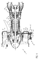
- FIG. 1 illustrates a schematic sectional view of a gas turbine engine 10.
- Air A enters the gas turbine engine 10 via a forward mounted fan 14, where the air A is directed into two discrete streams: a core air 16 and a bypass air 18.
- the core air 16 is pressurized in series by a low-pressure compressor 20 and a high-pressure compressor 22, then mixed with fuel, and burned in a combustor 24.
- the core air 16 exits the combustor 24 as exhaust combustion gases 26, which expand in series through a high-pressure turbine 28 and then a low-pressure turbine 30 before being exhausted from the engine 10.
- the exhaust combustion gases 26 in combination with the bypass air 18 generate forward propulsive thrust.
- the low-pressure turbine 28 drives the low-pressure compressor 20 via a low rotor spool 34 revolving about a central, longitudinal axis 36 of the engine 10 while the high-pressure turbine 30 drives the high-pressure compressor 22 via a high rotor spool 38.
- two compressors 20, 22 and two turbines 28, 30 are illustrated in the disclosed non-limiting embodiment, other engine configurations may be provided.
- the high rotor spool 38 remotely drives an externally mounted accessory gearbox system 40.
- a tower shaft 42 engages the high rotor spool 38 proximate the axis 36 through a first bevel gear set 44A and transfers the power radially outward through a second bevel gear set 44B within an angle gearbox 46.
- the power is then transferred via a lay shaft 48 to an accessory gearbox 50 which contains a gear train 51 to power at least one accessory system.
- the accessory gearbox 50 may be mounted to an engine frame section F - here illustrated as a fan frame section - for a minimal contribution to engine weight and reduced complexity. It should be understood that various accessory gearbox systems, mount locations and mount configurations may alternatively be provided.
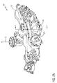
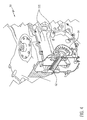
- the accessory gearbox 50 includes an accessory gearbox housing 52 having a multiple of seal air cores 52C in communication with an accessory compressor 54.
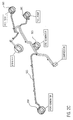
- the multiple of seal air cores 52C (also illustrated in Figures 2B, 2C ) are incorporated into the accessory gearbox housing 52.
- seal air is used in the accessory gearbox housing 52 to prevent oil from escaping about the accessory shaft seals 56A-56C.
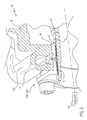
- Seal air S from the accessory compressor 54 travels though the multiple of seal air cores 52C and terminates at an outer section 58 of each of the labyrinth seals 56A-56C ( Figure 3 ). That is, seal air S generated by the accessory compressor 54 is communicated to each accessory shaft seal 56A-56C through a seal air core 52C.
- seal air S terminates at an outer section 58 and flows axially along each accessory shaft 60 rotationally retained therein.
- Seal air S1 flows toward an accessory 62 (illustrated schematically) driven by the accessory shaft 60 to prevent debris from entering into the accessory gearbox housing 52.
- Seal air S2 flows toward the interior of the accessory gearbox housing 52 to retain oil within the accessory gearbox housing 52.
- the accessory compressor 54 may be driven directly by the accessory gearbox 50 though a drive shaft 62.
- other drive systems such as an electric motor may power the accessory compressor 54.
- the accessory compressor 54 eliminates the requirement of either engine bleed air and the potential degradation therefrom to the accessory shaft seals 56A-56C.
- the interior of the accessory gearbox housing 52 typically operates at an elevated pressure relative to the local ambient.
- Gearbox internal pressure is typically approximately 10 PSI (69 kPa) above local ambient at take-off. This pressure is sealed therein by the accessory shaft seals 56A-56C.
- the accessory compressor 54 may draw air from within the interior of the accessory gearbox housing 52 such that the accessory compressor 54 need only slightly compress the air above the internal gearbox pressure to provide sufficient flow to properly seal the accessory gearbox housing 52. That is, the accessory gearbox housing 52 interior air is at an elevated pressure relative to the local ambient such that the accessory compressor 54 need only slightly compress the accessory gearbox housing 52 interior air to provide an effective seal. Approximately 2 PSI (14 kPa) above gearbox interior pressure is typically adequate for a proper seal.
- the accessory compressor 54 may communicate with ambient. Since ambient is at a relatively lower pressure than that within the accessory gearbox housing 52, the accessory compressor 54 may need to be of a somewhat increased capacity.
- the accessory compressor 54 may be a liquid ring accessory compressor.
- An impeller 62 which is offset within a housing 64 rotates and traps pockets of air in the space between a multiple of impeller fins 66 and the housing 64. As the impeller 62 rotates a pocket of air is trapped in the space between each of the fins 66. The trapped air is compressed between the impeller 62 and the housing 64 which is sealed with an annulus of oil 68. As the air is compressed by the impeller 62 such that an inlet port 70 on one face of the accessory compressor 54 draws air for compression and subsequent discharge through an outlet port 72 on an opposite face, fluid surface motion toward and away from impeller 62 center allows air to be drawn in and discharged without sliding contact.
- the accessory compressor 54' may alternatively be a sliding vane accessory compressor. Vanes 82 slide radially inward and outward within a respective slot 83 in a rotor 84.
- the rotor 84 is located off-center within a housing 86. As the rotor 84 rotates, the vanes 82 slide against the housing 86. As the rotor 84 is off-center, the vanes 82 move in and out of the rotor 86 such that a volume of air between the vanes 82 increases over one half of the rotation and decreases over the other half.
- An inlet port 88 is located at the point of largest volume and an output port 90 at a point of smallest volume. The inlet port 88 is located on one face of the accessory compressor 54' to draw air for compression and subsequent discharge through an outlet port 90 on an opposite face.
- the sliding vane accessory compressor may have greater thermal efficiency.
- Accessory compressor pressure rise is relatively low such that temperature increase (adiabatic compression plus efficiency loss) and heat transfer to the gearbox interior is also relatively low.
- Seal air flow at approximately 250 Deg F (normal) (121° C) and 300° F (147° C) on high-hot days is readily maintained. Such relatively low seal air temperatures extend gearbox housing material life.
Landscapes
- Engineering & Computer Science (AREA)
- Chemical & Material Sciences (AREA)
- Combustion & Propulsion (AREA)
- Mechanical Engineering (AREA)
- General Engineering & Computer Science (AREA)
- Structures Of Non-Positive Displacement Pumps (AREA)
- Turbine Rotor Nozzle Sealing (AREA)
- General Details Of Gearings (AREA)
Applications Claiming Priority (1)
| Application Number | Priority Date | Filing Date | Title |
|---|---|---|---|
| US12/107,811 US8172512B2 (en) | 2008-04-23 | 2008-04-23 | Accessory gearbox system with compressor driven seal air supply |
Publications (2)
| Publication Number | Publication Date |
|---|---|
| EP2112352A2 true EP2112352A2 (de) | 2009-10-28 |
| EP2112352A3 EP2112352A3 (de) | 2013-03-06 |
Family
ID=40468483
Family Applications (1)
| Application Number | Title | Priority Date | Filing Date |
|---|---|---|---|
| EP09250241A Withdrawn EP2112352A3 (de) | 2008-04-23 | 2009-01-29 | Getriebesystem für Hilfsaggregatgetriebe mit von einem Verdichter angetriebener Sperrluftzufuhr und Verfahren zur Bereitstellung der Sperrluftzufuhr an einem Hilfsaggregatgetriebe |
Country Status (3)
| Country | Link |
|---|---|
| US (1) | US8172512B2 (de) |
| EP (1) | EP2112352A3 (de) |
| JP (1) | JP4688940B2 (de) |
Cited By (4)
| Publication number | Priority date | Publication date | Assignee | Title |
|---|---|---|---|---|
| EP2362081A1 (de) | 2010-02-19 | 2011-08-31 | United Technologies Corporation | System zur Druckluftbeaufschlagung von Lagergehäusen und zur Wellenbelüftung |
| EP2951401A4 (de) * | 2013-01-30 | 2016-10-05 | United Technologies Corp | Hilfsgetriebe für einen gasturbinenmotor |
| EP2964936A4 (de) * | 2013-03-08 | 2016-11-02 | United Technologies Corp | Getriebemontageanordnung |
| EP3957833A1 (de) * | 2020-08-21 | 2022-02-23 | Pratt & Whitney Canada Corp. | Druckdichtungsanordnung |
Families Citing this family (22)
| Publication number | Priority date | Publication date | Assignee | Title |
|---|---|---|---|---|
| US20110148235A1 (en) * | 2009-12-18 | 2011-06-23 | Lemmers Jr Glenn C | Generator packaging arrangement |
| US20110314963A1 (en) * | 2010-06-28 | 2011-12-29 | Hamilton Sundstrand Corporation | Controllable constant speed gearbox |
| US8668463B2 (en) | 2010-07-29 | 2014-03-11 | United Technologies Corporation | Rotatable component mount for a gas turbine engine |
| CN103459807B (zh) | 2011-04-07 | 2016-08-17 | 川崎重工业株式会社 | 航空器发电装置 |
| US9394803B2 (en) * | 2012-03-14 | 2016-07-19 | United Technologies Corporation | Bypass air-pump system within the core engine to provide air for an environmental control system in a gas turbine engine |
| US9121346B2 (en) | 2012-03-14 | 2015-09-01 | United Technologies Corporation | Pump system for TMS AOC reduction |
| US9151224B2 (en) | 2012-03-14 | 2015-10-06 | United Technologies Corporation | Constant-speed pump system for engine thermal management system AOC reduction and environmental control system loss elimination |
| US8973465B2 (en) | 2012-07-20 | 2015-03-10 | United Technologies Corporation | Gearbox for gas turbine engine |
| US8955809B2 (en) | 2012-12-05 | 2015-02-17 | Hamilton Sundstrand Corporation | Three-way mount bracket for aircraft cabin air supply system |
| US9086131B2 (en) | 2013-01-24 | 2015-07-21 | Silver Ii Us Holdings, Llc | Gearbox output seal |
| CN103552693B (zh) * | 2013-10-29 | 2015-12-30 | 沈阳黎明航空发动机(集团)有限责任公司 | 一种便携式航发外置附件机匣自主转动装置 |
| US10017258B2 (en) | 2015-05-06 | 2018-07-10 | Hamilton Sundstrand Corporation | Compressor mount bracket for aircraft cabin air supply system |
| US10017275B2 (en) | 2015-05-06 | 2018-07-10 | Hamilton Sundstrand Corporation | Cross bracket for aircraft cabin air supply system |
| US11333076B2 (en) | 2017-12-21 | 2022-05-17 | Raytheon Technologies Corporation | Power takeoff transmission |
| US11085515B2 (en) | 2019-02-20 | 2021-08-10 | General Electric Company | Gearbox coupling in a turbomachine |
| US11073088B2 (en) | 2019-02-20 | 2021-07-27 | General Electric Company | Gearbox mounting in a turbomachine |
| US11021970B2 (en) | 2019-02-20 | 2021-06-01 | General Electric Company | Turbomachine with alternatingly spaced rotor blades |
| US11156097B2 (en) | 2019-02-20 | 2021-10-26 | General Electric Company | Turbomachine having an airflow management assembly |
| US11753939B2 (en) | 2019-02-20 | 2023-09-12 | General Electric Company | Turbomachine with alternatingly spaced rotor blades |
| US11415051B2 (en) | 2020-12-22 | 2022-08-16 | General Electric Company | System for lubricating components of a gas turbine engine including a lubricant bypass conduit |
| FR3135753B1 (fr) * | 2022-05-23 | 2024-04-19 | Safran Trans Systems | Boitier de relais d’accessoires pour une turbomachine |
| FR3135756B1 (fr) * | 2022-05-23 | 2024-05-03 | Safran Trans Systems | boitier de relais d’accessoires perfectionné |
Citations (5)
| Publication number | Priority date | Publication date | Assignee | Title |
|---|---|---|---|---|
| US3378104A (en) | 1966-03-08 | 1968-04-16 | Gen Electric | Air-oil separators for use in gas turbine engines |
| US4525995A (en) | 1983-04-04 | 1985-07-02 | Williams International Corporation | Oil scavening system for gas turbine engine |
| US4891934A (en) | 1988-10-31 | 1990-01-09 | General Motors Corporation | Oil system for gas turbine engine |
| US20050211093A1 (en) | 2004-03-23 | 2005-09-29 | Pratt & Whitney Canada Corp. | Air/oil separation system and method |
| US20080066444A1 (en) | 2006-09-14 | 2008-03-20 | Cornelius Charles C | Seal for a turbine engine |
Family Cites Families (31)
| Publication number | Priority date | Publication date | Assignee | Title |
|---|---|---|---|---|
| DE1000189B (de) | 1955-06-28 | 1957-01-03 | Bmw Studiengesellschaft Fuer T | Gasturbine, insbesondere Kleingasturbine |
| US2978869A (en) | 1956-11-01 | 1961-04-11 | Bristol Siddeley Engines Ltd | Engine accessory mounting arrangements |
| US2925215A (en) * | 1957-06-20 | 1960-02-16 | United Aircraft Corp | Lubrication system |
| US3830058A (en) | 1973-02-26 | 1974-08-20 | Avco Corp | Fan engine mounting |
| US3976165A (en) | 1974-05-03 | 1976-08-24 | Norwalk-Turbo, Inc. | Lubricating and oil seal system for a high speed compressor |
| US4057371A (en) | 1974-05-03 | 1977-11-08 | Norwalk-Turbo Inc. | Gas turbine driven high speed centrifugal compressor unit |
| US4594850A (en) | 1983-02-07 | 1986-06-17 | Williams International Corporation | Combined cycle total energy system |
| US4756664A (en) | 1985-10-03 | 1988-07-12 | Sundstrand Corporation | Scavenge oil system |
| US4682505A (en) | 1985-12-13 | 1987-07-28 | Pratt & Whitney Canada Inc. | Compact torque measurement system |
| US4713982A (en) | 1985-12-27 | 1987-12-22 | Sundstrand Corporation | Integral gear box and electrical generating system |
| US4817382A (en) | 1985-12-31 | 1989-04-04 | The Boeing Company | Turboprop propulsion apparatus |
| FR2607185B1 (fr) | 1986-11-20 | 1990-05-04 | Snecma | Systeme de lubrification pour demarreur de turbomachine |
| DE3714990A1 (de) | 1987-05-06 | 1988-12-01 | Mtu Muenchen Gmbh | Propfan-turbotriebwerk |
| US5110257A (en) | 1988-05-12 | 1992-05-05 | United Technologies Corporation | Apparatus for supporting a rotating shaft in a rotary machine |
| US5309708A (en) | 1988-06-03 | 1994-05-10 | Alliedsignal Inc. | Multifunction integrated power unit |
| EP0540192A1 (de) * | 1991-10-30 | 1993-05-05 | General Electric Company | Trägerplatte für Zusatzantriebe |
| GB9306890D0 (en) * | 1993-04-01 | 1993-06-02 | Bmw Rolls Royce Gmbh | A gas turbine engine with bearing chambers and barrier air chambers |
| US5555722A (en) | 1993-11-15 | 1996-09-17 | Sundstrand Corporation | Integrated APU |
| US6079198A (en) * | 1998-04-29 | 2000-06-27 | General Electric Co. | Pressure compensated fuel delivery system for the combustors of turbomachinery |
| US6357220B1 (en) | 1998-12-22 | 2002-03-19 | United Technologies Corporation | Gearbox accessory mount |
| JP2001271656A (ja) * | 2000-03-27 | 2001-10-05 | Honda Motor Co Ltd | ガスタービンエンジンの補機駆動ユニット |
| JP4375883B2 (ja) * | 2000-06-02 | 2009-12-02 | 本田技研工業株式会社 | ガスタービンエンジンの軸受へのシールエア供給装置 |
| US6571563B2 (en) | 2000-12-19 | 2003-06-03 | Honeywell Power Systems, Inc. | Gas turbine engine with offset shroud |
| GB0206243D0 (en) * | 2002-03-16 | 2002-05-01 | Rolls Royce Plc | An air/oil separator |
| JP2003269191A (ja) * | 2002-03-18 | 2003-09-25 | Ishikawajima Harima Heavy Ind Co Ltd | ガスタービンエンジン |
| JP2003286866A (ja) * | 2002-03-27 | 2003-10-10 | Ishikawajima Harima Heavy Ind Co Ltd | 航空エンジン用補機駆動ギアボックスの取付構造 |
| US7055303B2 (en) | 2003-12-22 | 2006-06-06 | Pratt & Whitney Canada Corp. | Gas turbine engine architecture |
| WO2005073540A1 (en) * | 2004-01-30 | 2005-08-11 | Pratt & Whitney Canada Corp. | Compact configuration for attaching a fuel pump or other accessory to an accessory gearbox |
| US20050183540A1 (en) | 2004-02-25 | 2005-08-25 | Miller Guy W. | Apparatus for driving an accessory gearbox in a gas turbine engine |
| US7093447B2 (en) * | 2004-08-25 | 2006-08-22 | Hamilton Sundstrand Corporation | Auxiliary power unit with an oil-free compressor |
| US7500365B2 (en) | 2005-05-05 | 2009-03-10 | United Technologies Corporation | Accessory gearbox |
-
2008
- 2008-04-23 US US12/107,811 patent/US8172512B2/en not_active Expired - Fee Related
-
2009
- 2009-01-29 EP EP09250241A patent/EP2112352A3/de not_active Withdrawn
- 2009-03-18 JP JP2009065358A patent/JP4688940B2/ja not_active Expired - Fee Related
Patent Citations (5)
| Publication number | Priority date | Publication date | Assignee | Title |
|---|---|---|---|---|
| US3378104A (en) | 1966-03-08 | 1968-04-16 | Gen Electric | Air-oil separators for use in gas turbine engines |
| US4525995A (en) | 1983-04-04 | 1985-07-02 | Williams International Corporation | Oil scavening system for gas turbine engine |
| US4891934A (en) | 1988-10-31 | 1990-01-09 | General Motors Corporation | Oil system for gas turbine engine |
| US20050211093A1 (en) | 2004-03-23 | 2005-09-29 | Pratt & Whitney Canada Corp. | Air/oil separation system and method |
| US20080066444A1 (en) | 2006-09-14 | 2008-03-20 | Cornelius Charles C | Seal for a turbine engine |
Cited By (7)
| Publication number | Priority date | Publication date | Assignee | Title |
|---|---|---|---|---|
| EP2362081A1 (de) | 2010-02-19 | 2011-08-31 | United Technologies Corporation | System zur Druckluftbeaufschlagung von Lagergehäusen und zur Wellenbelüftung |
| EP2951401A4 (de) * | 2013-01-30 | 2016-10-05 | United Technologies Corp | Hilfsgetriebe für einen gasturbinenmotor |
| US10641181B2 (en) | 2013-01-30 | 2020-05-05 | United Technologies Corporation | Gas turbine engine accessory gearbox |
| EP3741961A1 (de) * | 2013-01-30 | 2020-11-25 | Raytheon Technologies Corporation | Hilfsgetriebe für einen gasturbinenmotor |
| EP2964936A4 (de) * | 2013-03-08 | 2016-11-02 | United Technologies Corp | Getriebemontageanordnung |
| EP3957833A1 (de) * | 2020-08-21 | 2022-02-23 | Pratt & Whitney Canada Corp. | Druckdichtungsanordnung |
| US11686218B2 (en) | 2020-08-21 | 2023-06-27 | Pratt & Whitney Canada Corp. | Pressure seal assembly |
Also Published As
| Publication number | Publication date |
|---|---|
| US8172512B2 (en) | 2012-05-08 |
| JP4688940B2 (ja) | 2011-05-25 |
| EP2112352A3 (de) | 2013-03-06 |
| US20090324396A1 (en) | 2009-12-31 |
| JP2009264371A (ja) | 2009-11-12 |
Similar Documents
| Publication | Publication Date | Title |
|---|---|---|
| US8172512B2 (en) | Accessory gearbox system with compressor driven seal air supply | |
| EP2447507B1 (de) | Kühlanordnung für eine Turbomaschine | |
| US10927791B2 (en) | Engine assembly with combined engine and cooling exhaust | |
| US10240522B2 (en) | Auxiliary power unit with combined cooling of generator | |
| US8978352B2 (en) | Apparatus and method for operating a gas turbine engine during windmilling | |
| EP3260688B1 (de) | Kammerkühlung für einen gasturbinenmotor | |
| EP2584172B1 (de) | Getriebe mit konstanter Drehzahl für Gasturbinen-Motor | |
| EP2584169B1 (de) | Gasturbinenmotor mit Integriertem Wärmeverwaltungssystem | |
| EP2900965B1 (de) | Gasturbinenmotor-wärmeregelungssystem für wärmetauscher mit bypass-strömung | |
| US20130098057A1 (en) | Controllable speed windmill operation of a gas turbine engine through low spool power extraction | |
| CN111594275B (zh) | 具有气流管理组件的涡轮机 | |
| CN112236580A (zh) | 轴承贮槽的排气系统 | |
| EP2946082B1 (de) | Ölpumpentransferplatte | |
| CA2938108C (en) | Engine assembly with combined engine and cooling exhaust |
Legal Events
| Date | Code | Title | Description |
|---|---|---|---|
| PUAI | Public reference made under article 153(3) epc to a published international application that has entered the european phase |
Free format text: ORIGINAL CODE: 0009012 |
|
| AK | Designated contracting states |
Kind code of ref document: A2 Designated state(s): AT BE BG CH CY CZ DE DK EE ES FI FR GB GR HR HU IE IS IT LI LT LU LV MC MK MT NL NO PL PT RO SE SI SK TR |
|
| AX | Request for extension of the european patent |
Extension state: AL BA RS |
|
| PUAL | Search report despatched |
Free format text: ORIGINAL CODE: 0009013 |
|
| AK | Designated contracting states |
Kind code of ref document: A3 Designated state(s): AT BE BG CH CY CZ DE DK EE ES FI FR GB GR HR HU IE IS IT LI LT LU LV MC MK MT NL NO PL PT RO SE SI SK TR |
|
| AX | Request for extension of the european patent |
Extension state: AL BA RS |
|
| RIC1 | Information provided on ipc code assigned before grant |
Ipc: F02C 7/36 20060101ALI20130130BHEP Ipc: F01D 25/18 20060101ALI20130130BHEP Ipc: F02C 7/00 20060101AFI20130130BHEP Ipc: F02C 7/32 20060101ALI20130130BHEP |
|
| 17P | Request for examination filed |
Effective date: 20130830 |
|
| RBV | Designated contracting states (corrected) |
Designated state(s): AT BE BG CH CY CZ DE DK EE ES FI FR GB GR HR HU IE IS IT LI LT LU LV MC MK MT NL NO PL PT RO SE SI SK TR |
|
| AKX | Designation fees paid |
Designated state(s): DE FR GB |
|
| STAA | Information on the status of an ep patent application or granted ep patent |
Free format text: STATUS: THE APPLICATION HAS BEEN WITHDRAWN |
|
| 18W | Application withdrawn |
Effective date: 20131203 |