EP2112355A1 - Zündung und Absperrung der Kraftstoffzufuhr für Motor - Google Patents
Zündung und Absperrung der Kraftstoffzufuhr für Motor Download PDFInfo
- Publication number
- EP2112355A1 EP2112355A1 EP09157991A EP09157991A EP2112355A1 EP 2112355 A1 EP2112355 A1 EP 2112355A1 EP 09157991 A EP09157991 A EP 09157991A EP 09157991 A EP09157991 A EP 09157991A EP 2112355 A1 EP2112355 A1 EP 2112355A1
- Authority
- EP
- European Patent Office
- Prior art keywords
- lever
- carburetor
- fuel
- switch
- pivot
- Prior art date
- Legal status (The legal status is an assumption and is not a legal conclusion. Google has not performed a legal analysis and makes no representation as to the accuracy of the status listed.)
- Granted
Links
Images

Classifications
-
- F—MECHANICAL ENGINEERING; LIGHTING; HEATING; WEAPONS; BLASTING
- F02—COMBUSTION ENGINES; HOT-GAS OR COMBUSTION-PRODUCT ENGINE PLANTS
- F02D—CONTROLLING COMBUSTION ENGINES
- F02D17/00—Controlling engines by cutting out individual cylinders; Rendering engines inoperative or idling
- F02D17/04—Controlling engines by cutting out individual cylinders; Rendering engines inoperative or idling rendering engines inoperative or idling, e.g. caused by abnormal conditions
-
- F—MECHANICAL ENGINEERING; LIGHTING; HEATING; WEAPONS; BLASTING
- F02—COMBUSTION ENGINES; HOT-GAS OR COMBUSTION-PRODUCT ENGINE PLANTS
- F02D—CONTROLLING COMBUSTION ENGINES
- F02D11/00—Arrangements for, or adaptations to, non-automatic engine control initiation means, e.g. operator initiated
- F02D11/02—Arrangements for, or adaptations to, non-automatic engine control initiation means, e.g. operator initiated characterised by hand, foot, or like operator controlled initiation means
-
- F—MECHANICAL ENGINEERING; LIGHTING; HEATING; WEAPONS; BLASTING
- F02—COMBUSTION ENGINES; HOT-GAS OR COMBUSTION-PRODUCT ENGINE PLANTS
- F02M—SUPPLYING COMBUSTION ENGINES IN GENERAL WITH COMBUSTIBLE MIXTURES OR CONSTITUENTS THEREOF
- F02M37/00—Apparatus or systems for feeding liquid fuel from storage containers to carburettors or fuel-injection apparatus; Arrangements for purifying liquid fuel specially adapted for, or arranged on, internal-combustion engines
- F02M37/0011—Constructional details; Manufacturing or assembly of elements of fuel systems; Materials therefor
- F02M37/0023—Valves in the fuel supply and return system
Definitions
- the present invention relates to an ignition shutoff device and a fuel supply shutoff device for an engine.
- An ignition shutoff device for an engine grounds the ignition coil to prevent firing of the spark plug to kill the engine, or to prevent the engine from starting.
- fuel may move from the fuel tank into the combustion chamber and crankcase, which can wash away and dilute engine oil causing damage to the engine.
- Engine-driven products may include, but are not limited to, lawnmowers, edgers, augers, snow throwers, tillers, chippers, log splitters, generators and pressure washers, for example.
- the invention provides a carburetor assembly including a carburetor, a fuel supply valve, a valve member and a normally open switch.
- the carburetor includes a housing and is configured to supply fuel to a combustion chamber of an engine.
- the fuel supply valve is coupled to the carburetor housing and is fluidly connected to the carburetor upstream of the carburetor.
- the fuel supply valve includes a lever configured to pivot about a pivot axis between a first position and a second position.
- the lever includes a pivot portion through which the pivot axis passes and a handle portion fixed to the pivot portion and extending generally radially from the pivot portion in a direction.
- the pivot portion is configured to pivot about the pivot axis when an external force is applied to the handle portion.
- the valve member is configured to move in response to the lever such that fuel is allowed to flow to the carburetor when the lever is in the first position and fuel is not allowed to flow to the carburetor when the lever is in the second position.
- the normally open switch is adjacent the fuel supply valve and includes a switch actuator configured to move between an actuated position and a non-actuated position. The switch actuator is biased to the non-actuated position.
- the lever is configured to engage and release the switch actuator to move the switch actuator between the non-actuated position and the actuated position respectively when the lever moves between the first and second positions.
- the invention provides a carburetor assembly including a carburetor, a fuel valve, a valve member and a normally open switch.
- the carburetor includes a housing and is configured to supply fuel to an engine for combustion.
- the fuel valve is coupled to the carburetor housing and is configured to allow and prevent fuel flow to the carburetor.
- the fuel valve includes a lever configured to pivot about an axis between a first position and a second position.
- the lever includes a pivot through which the axis passes and a handle fixed to the pivot and extending away from the pivot in a direction.
- the pivot is configured to pivot about the axis when a force is applied to the handle.
- the valve member is coupled with the lever such that fuel is allowed to flow to the carburetor when the lever is in the first position and fuel is prevented from flowing to the carburetor when the lever is in the second position.
- the normally open switch is adjacent the fuel valve and includes a switch actuator configured to move between an actuated position and a non-actuated position. The switch actuator is biased to the non-actuated position.
- the lever is configured to press and release the switch actuator to move the switch actuator between the non-actuator position and the actuator position when the lever moves between the first and second positions.
- the invention provides a fuel and ignition shutoff system for an internal combustion engine including a carburetor shutoff valve, a valve member and a normally open switch.
- the carburetor shutoff valve is configured to selectively prevent and allow fuel from entering a carburetor.
- the shutoff valve has a lever including a pivot portion pivotable about a pivot axis and a handle portion fixed to the pivot portion and extending generally radially from the pivot portion in a direction.
- the pivot portion is configured to pivot about the pivot axis when an external force is applied to the handle portion.
- the valve member is coupled with the lever such that fuel is allowed to flow to the carburetor when the lever is in the first position and wherein fuel is not allowed to flow to the carburetor when the lever is in the second position.
- the normally open switch is adjacent the carburetor shutoff valve, the switch including a switch actuator configured to move between an actuated position and a non-actuated position, the switch being electrically connected to ground and to an ignition coil such that the ignition coil is electrically connected to ground when the switch is in the actuated position.
- the lever is configured such that the actuator engages and releases the switch actuator to move the switch actuator between the non-actuated position and the actuated position respectively when the lever moves between the first and second positions.
- the lever engages the actuation arm when the lever is in the second position such that the actuation arm is placed in the actuated position and such that the ignition coil is grounded.
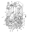
- Fig. 1 shows an internal combustion engine 10 including an ignition system 15, and a fuel tank 20 (shown in Fig. 5 ) fluidly connected to a fuel supply valve 25 and a carburetor 30.
- the ignition system includes an ignition coil 35 electrically connected to a spark plug 40 and to a normally open switch 45, such as a microswitch.
- the microswitch includes an actuation arm 50 biased to the open position, i.e., the actuation arm 50 is biased away from contact with the microswitch 45.
- a wire 55 electrically connected to the microswitch 45 at one end is electrically connected to the engine block 60 at another end, i.e., ground. In an open microswitch condition, there is no electrical connection between the ignition coil 35 and the grounded wire 55. However, in a closed condition, the ignition coil 35 is electrically grounded by way of the wire 55.
- the switch may include other types of switches, and other actuators may be employed.
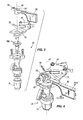
- the fuel tank 20 (shown in Fig. 5 ) is fluidly connected to the carburetor 30 by a fuel hose 21 (also shown in Fig. 5 ) and the fuel supply valve 25, which in the illustrated construction is a petcock valve including a valve member 95 that allows and prevents the flow of fuel from the fuel tank 20 to the carburetor 30, and a lever 65 coupled to the valve member 95 and pivotable about a pivot axis 90 and positioned adjacent a bracket 70 coupled to the microswitch 45 (see Figs. 3 and 4 ).
- the fuel supply valve 25 is coupled to a housing of the carburetor 30, which includes an optional sediment bowl 75, located adjacent the fuel supply valve 25 and centered about the pivot axis 90 in the illustrated construction.
- the lever 65 includes a handle portion 80, an actuator 85, and the pivot axis 90 through a pivot portion between the handle portion 80 and the actuator 85.
- the handle portion 80 extends generally radially from the pivot portion in a first direction and is manually operable by a user to rotate the lever 65 about the pivot axis 90 with the application of an external force.
- the actuator 85 extends generally radially from the pivot portion in a second direction, the second direction preferably being opposite the first direction.
- the actuator 85 In the open position shown in Fig. 1 , the actuator 85 is not in contact with the actuation arm 50 of the microswitch 45, which is normally open. Therefore, the ignition coil 35 operates normally, providing a periodic high-voltage ignition signal to the spark plug 40.
- other types of valves having pivoting levers may be employed.
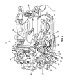
- Fig. 2 illustrates the fuel supply lever 65 in the closed position, such that the closed fuel supply valve 25 inhibits the flow of fuel to the carburettor 30.
- the actuator 85 is in contact with the actuation arm 50 such that the actuation arm 50 is depressed so as to close the microswitch 45.
- the ignition coil 35 is electrically grounded and therefore firing of the spark plug does not occur.
- the actuator 85 may be positioned elsewhere with respect to the lever 65 and may extend in a direction not opposite the first direction, and in other constructions, the handle portion 80 may provide the actuation function.
- the fuel supply lever 65 is positioned in the open position when operation of the engine 10 is desired.
- the open position fuel is supplied to the carburetor 30, and the microswitch 45 is open, allowing the ignition coil 35 to provide a periodic high-voltage ignition signal to the spark plug 40.
- the fuel supply lever 65 is pivoted about the pivot axis 90 to the closed position.
- the actuator 85 is pivoted into contact with the actuation arm 50 of the microwitch 45, such that the microswitch 45 is closed.
- the microswitch 45 is closed, the ignition coil 35 is grounded and therefore unable to provide an ignition signal to the spark plug 40.
- the engine 10 is therefore unable to run.
- the fuel supply valve 25 is also closed, preventing the movement of excess fuel into the carburetor 30, thereby preventing the movement of excess fuel into the combustion chamber and crankcase.
- the engine bearings in the crankcase are also protected from a condition in which fuel seeps into the crankcase and dilutes the engine oil. The movement of fuel may otherwise occur during transport when the fuel supply valve is inadvertently left open.
- the invention provides, among other things, an ignition and fuel shutoff lever.
Landscapes
- Engineering & Computer Science (AREA)
- Chemical & Material Sciences (AREA)
- Combustion & Propulsion (AREA)
- Mechanical Engineering (AREA)
- General Engineering & Computer Science (AREA)
- Control Of Throttle Valves Provided In The Intake System Or In The Exhaust System (AREA)
- Output Control And Ontrol Of Special Type Engine (AREA)
Applications Claiming Priority (1)
| Application Number | Priority Date | Filing Date | Title |
|---|---|---|---|
| US4691108P | 2008-04-22 | 2008-04-22 |
Publications (2)
| Publication Number | Publication Date |
|---|---|
| EP2112355A1 true EP2112355A1 (de) | 2009-10-28 |
| EP2112355B1 EP2112355B1 (de) | 2015-01-07 |
Family
ID=40740128
Family Applications (1)
| Application Number | Title | Priority Date | Filing Date |
|---|---|---|---|
| EP09157991.2A Active EP2112355B1 (de) | 2008-04-22 | 2009-04-15 | Absperrung der Zündung und der Kraftstoffzufuhr für Motor |
Country Status (3)
| Country | Link |
|---|---|
| US (1) | US8408183B2 (de) |
| EP (1) | EP2112355B1 (de) |
| CN (1) | CN101566110B (de) |
Cited By (4)
| Publication number | Priority date | Publication date | Assignee | Title |
|---|---|---|---|---|
| EP2423497A1 (de) * | 2010-08-24 | 2012-02-29 | Honda Motor Co., Ltd. | Kraftstoffhahn-integrierter Motorschalter |
| US20140338634A1 (en) * | 2013-05-20 | 2014-11-20 | Kohler Co. | Automatic Fuel Shutoff |
| US9074535B1 (en) | 2013-12-19 | 2015-07-07 | Kohler Co. | Integrated engine control apparatus and method of operating same |
| US10054081B2 (en) | 2014-10-17 | 2018-08-21 | Kohler Co. | Automatic starting system |
Families Citing this family (6)
| Publication number | Priority date | Publication date | Assignee | Title |
|---|---|---|---|---|
| USD685897S1 (en) * | 2010-12-03 | 2013-07-09 | Briggs & Stratton Corporation | Air filter |
| DE102011100155A1 (de) * | 2011-05-02 | 2012-11-08 | Bomag Gmbh | Betätigungseinrichtung für ein Bodenverdichtungsgerät mit Verbrennungsmotor, Bodenverdichtungsgerät mit einer solchen Betätigungseinrichtung und Betätigungsmittel |
| CN102722648A (zh) * | 2012-05-31 | 2012-10-10 | 深圳市纽泰克电子有限公司 | 移动临场会诊系统 |
| EP3369921B1 (de) * | 2017-03-02 | 2023-04-19 | Briggs & Stratton, LLC | Motordrehzahlregelsystem |
| US11326566B2 (en) * | 2017-03-02 | 2022-05-10 | Briggs & Stratton, Llc | Transport valve system for outdoor power equipment |
| US11111861B2 (en) * | 2017-03-03 | 2021-09-07 | Briggs & Stratton, Llc | Engine speed control system |
Citations (8)
| Publication number | Priority date | Publication date | Assignee | Title |
|---|---|---|---|---|
| US1881251A (en) * | 1930-10-06 | 1932-10-04 | Jr Robert H Tobener | Throttle ignition switch |
| US4510739A (en) | 1982-07-23 | 1985-04-16 | Fichtel & Sachs Ag | Lawn mower |
| US5720250A (en) * | 1995-12-29 | 1998-02-24 | Wacker Werke Gmbh & Co. Kg | Throttle actuating device for internal combustion engines with diaphragm carburetor to be used with soil compacting devices |
| US6082323A (en) | 1997-01-08 | 2000-07-04 | Briggs & Stratton Corporation | Fuel shutoff system |
| EP1104824A1 (de) * | 1999-12-01 | 2001-06-06 | Svedala Compaction Equipment AB | Vibrationsstampfer mit einem einzigen Steuerhebel |
| US20020112701A1 (en) | 2001-02-20 | 2002-08-22 | Gracyalny Gary J. | Automatic fuel vent closure and fuel shutoff apparatus having mechanical actuation |
| US20070006840A1 (en) | 2005-07-06 | 2007-01-11 | Dynapac Compaction Equipment Ab | Operating apparatus for controlling a vibratory rammer |
| US20070234999A1 (en) * | 2006-04-11 | 2007-10-11 | Mikasa Sangyo Co., Ltd. | Throttle regulator for vibration compaction machine |
Family Cites Families (18)
| Publication number | Priority date | Publication date | Assignee | Title |
|---|---|---|---|---|
| US3158144A (en) | 1964-11-24 | Walker | ||
| JPS498721B1 (de) | 1970-12-17 | 1974-02-28 | ||
| US4058105A (en) | 1976-04-15 | 1977-11-15 | Scorpion, Inc. | Snowmobile safety switch system |
| DE7927688U1 (de) | 1979-09-28 | 1980-08-14 | Achterholt, Rainer, 8963 Waltenhofen | Kraftfahrzeug mit elektronischer motorabschaltvorrichtung |
| DE3025539A1 (de) | 1980-07-05 | 1982-01-28 | Volkswagenwerk Ag, 3180 Wolfsburg | Fahrzeug, insbesondere kraftfahrzeug |
| JPS60261937A (ja) | 1984-06-09 | 1985-12-25 | Yamaha Motor Co Ltd | デイ−ゼルエンジンの緊急停止装置 |
| US4856471A (en) | 1987-11-30 | 1989-08-15 | Pettinelli Anthony J | Automatic engine ignition shut-off device |
| US6024068A (en) | 1996-11-22 | 2000-02-15 | Yamaha Hatsudoki Kabushiki Kaisha | Watercraft engine control |
| US6213083B1 (en) * | 1997-01-08 | 2001-04-10 | Briggs & Stratton Corporation | Fuel shutoff system |
| US6371074B1 (en) * | 1999-06-29 | 2002-04-16 | John M. Keller | Method and apparatus for preventing backfiring in spark ignition, internal combustion engines |
| JP2001200735A (ja) | 2000-01-18 | 2001-07-27 | Honda Motor Co Ltd | 作業機のスロットル調整装置 |
| US6612881B2 (en) | 2000-08-04 | 2003-09-02 | Yamaha Marine Kabushiki Kaisha | Engine control arrangement for watercraft |
| US6691683B2 (en) * | 2001-03-28 | 2004-02-17 | Briggs & Stratton Corporation | Automatic fuel vent closure and fuel shutoff apparatus having electrical actuation |
| US6640770B2 (en) * | 2001-10-04 | 2003-11-04 | Walbro Corporation | Evaporative emission control apparatus for a combustion engine |
| US7131430B2 (en) | 2002-09-10 | 2006-11-07 | Tecumseh Products Company | Emissions control system for small internal combustion engines |
| US7165536B2 (en) | 2004-06-14 | 2007-01-23 | Tecumseh Products Company | Evaporative emissions control system for small internal combustion engines |
| JP4380518B2 (ja) | 2004-12-08 | 2009-12-09 | トヨタ自動車株式会社 | 内燃機関の制御装置 |
| US7231900B1 (en) * | 2005-04-22 | 2007-06-19 | Hanshaw Michael S | Small engine shut off system |
-
2009
- 2009-04-07 US US12/419,458 patent/US8408183B2/en active Active
- 2009-04-15 EP EP09157991.2A patent/EP2112355B1/de active Active
- 2009-04-21 CN CN200910136814.7A patent/CN101566110B/zh active Active
Patent Citations (8)
| Publication number | Priority date | Publication date | Assignee | Title |
|---|---|---|---|---|
| US1881251A (en) * | 1930-10-06 | 1932-10-04 | Jr Robert H Tobener | Throttle ignition switch |
| US4510739A (en) | 1982-07-23 | 1985-04-16 | Fichtel & Sachs Ag | Lawn mower |
| US5720250A (en) * | 1995-12-29 | 1998-02-24 | Wacker Werke Gmbh & Co. Kg | Throttle actuating device for internal combustion engines with diaphragm carburetor to be used with soil compacting devices |
| US6082323A (en) | 1997-01-08 | 2000-07-04 | Briggs & Stratton Corporation | Fuel shutoff system |
| EP1104824A1 (de) * | 1999-12-01 | 2001-06-06 | Svedala Compaction Equipment AB | Vibrationsstampfer mit einem einzigen Steuerhebel |
| US20020112701A1 (en) | 2001-02-20 | 2002-08-22 | Gracyalny Gary J. | Automatic fuel vent closure and fuel shutoff apparatus having mechanical actuation |
| US20070006840A1 (en) | 2005-07-06 | 2007-01-11 | Dynapac Compaction Equipment Ab | Operating apparatus for controlling a vibratory rammer |
| US20070234999A1 (en) * | 2006-04-11 | 2007-10-11 | Mikasa Sangyo Co., Ltd. | Throttle regulator for vibration compaction machine |
Cited By (7)
| Publication number | Priority date | Publication date | Assignee | Title |
|---|---|---|---|---|
| EP2423497A1 (de) * | 2010-08-24 | 2012-02-29 | Honda Motor Co., Ltd. | Kraftstoffhahn-integrierter Motorschalter |
| US8667941B2 (en) | 2010-08-24 | 2014-03-11 | Honda Motor Co., Ltd. | Fuel cock-integrated engine switch |
| US20140338634A1 (en) * | 2013-05-20 | 2014-11-20 | Kohler Co. | Automatic Fuel Shutoff |
| US9261030B2 (en) | 2013-05-20 | 2016-02-16 | Kohler Co. | Automatic fuel shutoff |
| US9739214B2 (en) | 2013-05-20 | 2017-08-22 | Kohler, Co. | Automatic fuel shutoff |
| US9074535B1 (en) | 2013-12-19 | 2015-07-07 | Kohler Co. | Integrated engine control apparatus and method of operating same |
| US10054081B2 (en) | 2014-10-17 | 2018-08-21 | Kohler Co. | Automatic starting system |
Also Published As
| Publication number | Publication date |
|---|---|
| CN101566110A (zh) | 2009-10-28 |
| US20090260596A1 (en) | 2009-10-22 |
| EP2112355B1 (de) | 2015-01-07 |
| CN101566110B (zh) | 2015-04-22 |
| US8408183B2 (en) | 2013-04-02 |
Similar Documents
| Publication | Publication Date | Title |
|---|---|---|
| US8408183B2 (en) | Ignition and fuel shutoff for engine | |
| US7886706B2 (en) | Engine starting system | |
| US6691683B2 (en) | Automatic fuel vent closure and fuel shutoff apparatus having electrical actuation | |
| CN104179596B (zh) | 化油器以及使用化油器进行自动断油的方法 | |
| EP2886836B1 (de) | Integrierte Motorsteuerungsvorrichtung und Verfahren zum Betrieb davon | |
| US9528450B2 (en) | Hand-held power tool with an internal combustion engine | |
| AU694768B2 (en) | Control system for power tool with internal combustion engine | |
| US5720250A (en) | Throttle actuating device for internal combustion engines with diaphragm carburetor to be used with soil compacting devices | |
| US20100224466A1 (en) | Portable handheld work apparatus | |
| US6986340B2 (en) | Automatic fuel vent closure and fuel shutoff apparatus having mechanical actuation | |
| EP1907678B1 (de) | Mehrzweckmotor | |
| US11326566B2 (en) | Transport valve system for outdoor power equipment | |
| US5943997A (en) | Evaporative emissions control for carburetors | |
| FR2676507A1 (fr) | Regulateur de mode de fonctionnement pour un moteur thermique. | |
| EP0867606A2 (de) | Ausbildung einer Bedienungstafel einer Brennkraftmaschine | |
| US7121533B2 (en) | Air filter housing with tamper resistant carburetor feature | |
| US5750056A (en) | Remotely controlled primer actuator for power equipment engines | |
| EP3369920A1 (de) | Transportventilsystem für aussenantriebsaggregat | |
| US7231900B1 (en) | Small engine shut off system | |
| US9217410B2 (en) | Single point engine control interface | |
| US20110030640A1 (en) | Choke and priming system for an internal combustion engine | |
| US20100193338A1 (en) | Switch arrangement | |
| WO2019226883A1 (en) | Throttle position sensor | |
| JP2020010628A (ja) | 手持式作業機 | |
| JPS5830104Y2 (ja) | エンジンの緊急停止装置 |
Legal Events
| Date | Code | Title | Description |
|---|---|---|---|
| PUAI | Public reference made under article 153(3) epc to a published international application that has entered the european phase |
Free format text: ORIGINAL CODE: 0009012 |
|
| AK | Designated contracting states |
Kind code of ref document: A1 Designated state(s): AT BE BG CH CY CZ DE DK EE ES FI FR GB GR HR HU IE IS IT LI LT LU LV MC MK MT NL NO PL PT RO SE SI SK TR |
|
| 17P | Request for examination filed |
Effective date: 20100219 |
|
| 17Q | First examination report despatched |
Effective date: 20100331 |
|
| GRAP | Despatch of communication of intention to grant a patent |
Free format text: ORIGINAL CODE: EPIDOSNIGR1 |
|
| INTG | Intention to grant announced |
Effective date: 20140626 |
|
| GRAP | Despatch of communication of intention to grant a patent |
Free format text: ORIGINAL CODE: EPIDOSNIGR1 |
|
| GRAS | Grant fee paid |
Free format text: ORIGINAL CODE: EPIDOSNIGR3 |
|
| GRAA | (expected) grant |
Free format text: ORIGINAL CODE: 0009210 |
|
| INTG | Intention to grant announced |
Effective date: 20141120 |
|
| RAP1 | Party data changed (applicant data changed or rights of an application transferred) |
Owner name: BRIGGS & STRATTON CORPORATION |
|
| AK | Designated contracting states |
Kind code of ref document: B1 Designated state(s): AT BE BG CH CY CZ DE DK EE ES FI FR GB GR HR HU IE IS IT LI LT LU LV MC MK MT NL NO PL PT RO SE SI SK TR |
|
| REG | Reference to a national code |
Ref country code: GB Ref legal event code: FG4D |
|
| REG | Reference to a national code |
Ref country code: CH Ref legal event code: EP |
|
| REG | Reference to a national code |
Ref country code: IE Ref legal event code: FG4D |
|
| REG | Reference to a national code |
Ref country code: AT Ref legal event code: REF Ref document number: 705904 Country of ref document: AT Kind code of ref document: T Effective date: 20150215 |
|
| REG | Reference to a national code |
Ref country code: DE Ref legal event code: R096 Ref document number: 602009028785 Country of ref document: DE Effective date: 20150219 |
|
| REG | Reference to a national code |
Ref country code: NL Ref legal event code: VDEP Effective date: 20150107 |
|
| REG | Reference to a national code |
Ref country code: AT Ref legal event code: MK05 Ref document number: 705904 Country of ref document: AT Kind code of ref document: T Effective date: 20150107 |
|
| REG | Reference to a national code |
Ref country code: LT Ref legal event code: MG4D |
|
| PG25 | Lapsed in a contracting state [announced via postgrant information from national office to epo] |
Ref country code: BG Free format text: LAPSE BECAUSE OF FAILURE TO SUBMIT A TRANSLATION OF THE DESCRIPTION OR TO PAY THE FEE WITHIN THE PRESCRIBED TIME-LIMIT Effective date: 20150407 Ref country code: SE Free format text: LAPSE BECAUSE OF FAILURE TO SUBMIT A TRANSLATION OF THE DESCRIPTION OR TO PAY THE FEE WITHIN THE PRESCRIBED TIME-LIMIT Effective date: 20150107 Ref country code: LT Free format text: LAPSE BECAUSE OF FAILURE TO SUBMIT A TRANSLATION OF THE DESCRIPTION OR TO PAY THE FEE WITHIN THE PRESCRIBED TIME-LIMIT Effective date: 20150107 Ref country code: HR Free format text: LAPSE BECAUSE OF FAILURE TO SUBMIT A TRANSLATION OF THE DESCRIPTION OR TO PAY THE FEE WITHIN THE PRESCRIBED TIME-LIMIT Effective date: 20150107 Ref country code: FI Free format text: LAPSE BECAUSE OF FAILURE TO SUBMIT A TRANSLATION OF THE DESCRIPTION OR TO PAY THE FEE WITHIN THE PRESCRIBED TIME-LIMIT Effective date: 20150107 Ref country code: NO Free format text: LAPSE BECAUSE OF FAILURE TO SUBMIT A TRANSLATION OF THE DESCRIPTION OR TO PAY THE FEE WITHIN THE PRESCRIBED TIME-LIMIT Effective date: 20150407 Ref country code: ES Free format text: LAPSE BECAUSE OF FAILURE TO SUBMIT A TRANSLATION OF THE DESCRIPTION OR TO PAY THE FEE WITHIN THE PRESCRIBED TIME-LIMIT Effective date: 20150107 |
|
| PG25 | Lapsed in a contracting state [announced via postgrant information from national office to epo] |
Ref country code: NL Free format text: LAPSE BECAUSE OF FAILURE TO SUBMIT A TRANSLATION OF THE DESCRIPTION OR TO PAY THE FEE WITHIN THE PRESCRIBED TIME-LIMIT Effective date: 20150107 Ref country code: IS Free format text: LAPSE BECAUSE OF FAILURE TO SUBMIT A TRANSLATION OF THE DESCRIPTION OR TO PAY THE FEE WITHIN THE PRESCRIBED TIME-LIMIT Effective date: 20150507 Ref country code: PL Free format text: LAPSE BECAUSE OF FAILURE TO SUBMIT A TRANSLATION OF THE DESCRIPTION OR TO PAY THE FEE WITHIN THE PRESCRIBED TIME-LIMIT Effective date: 20150107 Ref country code: GR Free format text: LAPSE BECAUSE OF FAILURE TO SUBMIT A TRANSLATION OF THE DESCRIPTION OR TO PAY THE FEE WITHIN THE PRESCRIBED TIME-LIMIT Effective date: 20150408 Ref country code: AT Free format text: LAPSE BECAUSE OF FAILURE TO SUBMIT A TRANSLATION OF THE DESCRIPTION OR TO PAY THE FEE WITHIN THE PRESCRIBED TIME-LIMIT Effective date: 20150107 Ref country code: LV Free format text: LAPSE BECAUSE OF FAILURE TO SUBMIT A TRANSLATION OF THE DESCRIPTION OR TO PAY THE FEE WITHIN THE PRESCRIBED TIME-LIMIT Effective date: 20150107 |
|
| REG | Reference to a national code |
Ref country code: DE Ref legal event code: R097 Ref document number: 602009028785 Country of ref document: DE |
|
| PG25 | Lapsed in a contracting state [announced via postgrant information from national office to epo] |
Ref country code: RO Free format text: LAPSE BECAUSE OF FAILURE TO SUBMIT A TRANSLATION OF THE DESCRIPTION OR TO PAY THE FEE WITHIN THE PRESCRIBED TIME-LIMIT Effective date: 20150107 Ref country code: SK Free format text: LAPSE BECAUSE OF FAILURE TO SUBMIT A TRANSLATION OF THE DESCRIPTION OR TO PAY THE FEE WITHIN THE PRESCRIBED TIME-LIMIT Effective date: 20150107 Ref country code: EE Free format text: LAPSE BECAUSE OF FAILURE TO SUBMIT A TRANSLATION OF THE DESCRIPTION OR TO PAY THE FEE WITHIN THE PRESCRIBED TIME-LIMIT Effective date: 20150107 Ref country code: DK Free format text: LAPSE BECAUSE OF FAILURE TO SUBMIT A TRANSLATION OF THE DESCRIPTION OR TO PAY THE FEE WITHIN THE PRESCRIBED TIME-LIMIT Effective date: 20150107 Ref country code: CZ Free format text: LAPSE BECAUSE OF FAILURE TO SUBMIT A TRANSLATION OF THE DESCRIPTION OR TO PAY THE FEE WITHIN THE PRESCRIBED TIME-LIMIT Effective date: 20150107 |
|
| PLBE | No opposition filed within time limit |
Free format text: ORIGINAL CODE: 0009261 |
|
| STAA | Information on the status of an ep patent application or granted ep patent |
Free format text: STATUS: NO OPPOSITION FILED WITHIN TIME LIMIT |
|
| PG25 | Lapsed in a contracting state [announced via postgrant information from national office to epo] |
Ref country code: MC Free format text: LAPSE BECAUSE OF FAILURE TO SUBMIT A TRANSLATION OF THE DESCRIPTION OR TO PAY THE FEE WITHIN THE PRESCRIBED TIME-LIMIT Effective date: 20150107 Ref country code: LU Free format text: LAPSE BECAUSE OF FAILURE TO SUBMIT A TRANSLATION OF THE DESCRIPTION OR TO PAY THE FEE WITHIN THE PRESCRIBED TIME-LIMIT Effective date: 20150415 |
|
| REG | Reference to a national code |
Ref country code: CH Ref legal event code: PL |
|
| 26N | No opposition filed |
Effective date: 20151008 |
|
| REG | Reference to a national code |
Ref country code: IE Ref legal event code: MM4A |
|
| PG25 | Lapsed in a contracting state [announced via postgrant information from national office to epo] |
Ref country code: LI Free format text: LAPSE BECAUSE OF NON-PAYMENT OF DUE FEES Effective date: 20150430 Ref country code: CH Free format text: LAPSE BECAUSE OF NON-PAYMENT OF DUE FEES Effective date: 20150430 |
|
| PG25 | Lapsed in a contracting state [announced via postgrant information from national office to epo] |
Ref country code: SI Free format text: LAPSE BECAUSE OF FAILURE TO SUBMIT A TRANSLATION OF THE DESCRIPTION OR TO PAY THE FEE WITHIN THE PRESCRIBED TIME-LIMIT Effective date: 20150107 |
|
| REG | Reference to a national code |
Ref country code: FR Ref legal event code: PLFP Year of fee payment: 8 |
|
| PG25 | Lapsed in a contracting state [announced via postgrant information from national office to epo] |
Ref country code: IE Free format text: LAPSE BECAUSE OF NON-PAYMENT OF DUE FEES Effective date: 20150415 |
|
| PG25 | Lapsed in a contracting state [announced via postgrant information from national office to epo] |
Ref country code: BE Free format text: LAPSE BECAUSE OF FAILURE TO SUBMIT A TRANSLATION OF THE DESCRIPTION OR TO PAY THE FEE WITHIN THE PRESCRIBED TIME-LIMIT Effective date: 20150107 |
|
| PG25 | Lapsed in a contracting state [announced via postgrant information from national office to epo] |
Ref country code: MT Free format text: LAPSE BECAUSE OF FAILURE TO SUBMIT A TRANSLATION OF THE DESCRIPTION OR TO PAY THE FEE WITHIN THE PRESCRIBED TIME-LIMIT Effective date: 20150107 |
|
| REG | Reference to a national code |
Ref country code: FR Ref legal event code: PLFP Year of fee payment: 9 |
|
| PG25 | Lapsed in a contracting state [announced via postgrant information from national office to epo] |
Ref country code: HU Free format text: LAPSE BECAUSE OF FAILURE TO SUBMIT A TRANSLATION OF THE DESCRIPTION OR TO PAY THE FEE WITHIN THE PRESCRIBED TIME-LIMIT; INVALID AB INITIO Effective date: 20090415 |
|
| PG25 | Lapsed in a contracting state [announced via postgrant information from national office to epo] |
Ref country code: CY Free format text: LAPSE BECAUSE OF FAILURE TO SUBMIT A TRANSLATION OF THE DESCRIPTION OR TO PAY THE FEE WITHIN THE PRESCRIBED TIME-LIMIT Effective date: 20150107 |
|
| PG25 | Lapsed in a contracting state [announced via postgrant information from national office to epo] |
Ref country code: PT Free format text: LAPSE BECAUSE OF FAILURE TO SUBMIT A TRANSLATION OF THE DESCRIPTION OR TO PAY THE FEE WITHIN THE PRESCRIBED TIME-LIMIT Effective date: 20150507 |
|
| PG25 | Lapsed in a contracting state [announced via postgrant information from national office to epo] |
Ref country code: TR Free format text: LAPSE BECAUSE OF FAILURE TO SUBMIT A TRANSLATION OF THE DESCRIPTION OR TO PAY THE FEE WITHIN THE PRESCRIBED TIME-LIMIT Effective date: 20150107 |
|
| REG | Reference to a national code |
Ref country code: FR Ref legal event code: PLFP Year of fee payment: 10 |
|
| PG25 | Lapsed in a contracting state [announced via postgrant information from national office to epo] |
Ref country code: MK Free format text: LAPSE BECAUSE OF FAILURE TO SUBMIT A TRANSLATION OF THE DESCRIPTION OR TO PAY THE FEE WITHIN THE PRESCRIBED TIME-LIMIT Effective date: 20150107 |
|
| REG | Reference to a national code |
Ref country code: GB Ref legal event code: 732E Free format text: REGISTERED BETWEEN 20211111 AND 20211117 |
|
| REG | Reference to a national code |
Ref country code: DE Ref legal event code: R081 Ref document number: 602009028785 Country of ref document: DE Owner name: BRIGGS & STRATTON, LLC, WAUWATOSA, US Free format text: FORMER OWNER: BRIGGS & STRATTON CORP., WAUWATOSA, WIS., US |
|
| P01 | Opt-out of the competence of the unified patent court (upc) registered |
Effective date: 20230703 |
|
| PGFP | Annual fee paid to national office [announced via postgrant information from national office to epo] |
Ref country code: DE Payment date: 20250428 Year of fee payment: 17 |
|
| PGFP | Annual fee paid to national office [announced via postgrant information from national office to epo] |
Ref country code: GB Payment date: 20250422 Year of fee payment: 17 |
|
| PGFP | Annual fee paid to national office [announced via postgrant information from national office to epo] |
Ref country code: IT Payment date: 20250422 Year of fee payment: 17 |
|
| PGFP | Annual fee paid to national office [announced via postgrant information from national office to epo] |
Ref country code: FR Payment date: 20250424 Year of fee payment: 17 |