EP2112367A1 - Agencement de couplage et injecteur de carburant - Google Patents
Agencement de couplage et injecteur de carburant Download PDFInfo
- Publication number
- EP2112367A1 EP2112367A1 EP08007858A EP08007858A EP2112367A1 EP 2112367 A1 EP2112367 A1 EP 2112367A1 EP 08007858 A EP08007858 A EP 08007858A EP 08007858 A EP08007858 A EP 08007858A EP 2112367 A1 EP2112367 A1 EP 2112367A1
- Authority
- EP
- European Patent Office
- Prior art keywords
- ring
- fuel injector
- housing
- separating element
- injector cup
- Prior art date
- Legal status (The legal status is an assumption and is not a legal conclusion. Google has not performed a legal analysis and makes no representation as to the accuracy of the status listed.)
- Granted
Links
Images


Classifications
-
- F—MECHANICAL ENGINEERING; LIGHTING; HEATING; WEAPONS; BLASTING
- F02—COMBUSTION ENGINES; HOT-GAS OR COMBUSTION-PRODUCT ENGINE PLANTS
- F02M—SUPPLYING COMBUSTION ENGINES IN GENERAL WITH COMBUSTIBLE MIXTURES OR CONSTITUENTS THEREOF
- F02M69/00—Low-pressure fuel-injection apparatus ; Apparatus with both continuous and intermittent injection; Apparatus injecting different types of fuel
- F02M69/46—Details, component parts or accessories not provided for in, or of interest apart from, the apparatus covered by groups F02M69/02 - F02M69/44
- F02M69/462—Arrangement of fuel conduits, e.g. with valves for maintaining pressure in the pipes after the engine being shut-down
- F02M69/465—Arrangement of fuel conduits, e.g. with valves for maintaining pressure in the pipes after the engine being shut-down of fuel rails
-
- F—MECHANICAL ENGINEERING; LIGHTING; HEATING; WEAPONS; BLASTING
- F02—COMBUSTION ENGINES; HOT-GAS OR COMBUSTION-PRODUCT ENGINE PLANTS
- F02M—SUPPLYING COMBUSTION ENGINES IN GENERAL WITH COMBUSTIBLE MIXTURES OR CONSTITUENTS THEREOF
- F02M55/00—Fuel-injection apparatus characterised by their fuel conduits or their venting means; Arrangements of conduits between fuel tank and pump F02M37/00
- F02M55/004—Joints; Sealings
- F02M55/005—Joints; Sealings for high pressure conduits, e.g. connected to pump outlet or to injector inlet
-
- F—MECHANICAL ENGINEERING; LIGHTING; HEATING; WEAPONS; BLASTING
- F02—COMBUSTION ENGINES; HOT-GAS OR COMBUSTION-PRODUCT ENGINE PLANTS
- F02M—SUPPLYING COMBUSTION ENGINES IN GENERAL WITH COMBUSTIBLE MIXTURES OR CONSTITUENTS THEREOF
- F02M55/00—Fuel-injection apparatus characterised by their fuel conduits or their venting means; Arrangements of conduits between fuel tank and pump F02M37/00
- F02M55/02—Conduits between injection pumps and injectors, e.g. conduits between pump and common-rail or conduits between common-rail and injectors
- F02M55/025—Common rails
-
- F—MECHANICAL ENGINEERING; LIGHTING; HEATING; WEAPONS; BLASTING
- F02—COMBUSTION ENGINES; HOT-GAS OR COMBUSTION-PRODUCT ENGINE PLANTS
- F02M—SUPPLYING COMBUSTION ENGINES IN GENERAL WITH COMBUSTIBLE MIXTURES OR CONSTITUENTS THEREOF
- F02M61/00—Fuel-injectors not provided for in groups F02M39/00 - F02M57/00 or F02M67/00
- F02M61/14—Arrangements of injectors with respect to engines; Mounting of injectors
-
- F—MECHANICAL ENGINEERING; LIGHTING; HEATING; WEAPONS; BLASTING
- F02—COMBUSTION ENGINES; HOT-GAS OR COMBUSTION-PRODUCT ENGINE PLANTS
- F02M—SUPPLYING COMBUSTION ENGINES IN GENERAL WITH COMBUSTIBLE MIXTURES OR CONSTITUENTS THEREOF
- F02M2200/00—Details of fuel-injection apparatus, not otherwise provided for
- F02M2200/85—Mounting of fuel injection apparatus
- F02M2200/858—Mounting of fuel injection apparatus sealing arrangements between injector and engine
Definitions
- the invention relates to a coupling arrangement for coupling a fuel injector to a fuel rail of a combustion engine and the fuel injector.
- Coupling arrangements for hydraulically and mechanically coupling a fuel injector to a fuel rail are in widespread use, in particular for internal combustion engines.
- Fuel can be supplied to an internal combustion engine by the fuel rail assembly through the fuel injector.
- the fuel injectors can be coupled to the fuel injector cups in different manners.
- Known fuel rails comprise a hollow body with recesses in form of fuel injector cups, wherein the fuel injectors are arranged.
- the connection of the fuel injectors to the fuel injector cups that supply the fuel from a fuel tank via a low or high-pressure fuel pump needs to be very precise to get a correct injection angle and a sealing of the fuel.
- the object of the invention is to create a coupling arrangement for coupling a fuel injector to a fuel rail which is simply to be manufactured and which facilitates a reliable operation.
- the invention is distinguished by a coupling arrangement for coupling a fuel injector to a fuel rail of a combustion engine, the coupling arrangement comprising a fuel injector cup having a central longitudinal axis and being designed to be coupled to the fuel rail at a first axial end area of the fuel injector cup, a housing of the fuel injector being arranged at the central longitudinal axis facing a second axial end area of the fuel injector cup, an O-ring seal being arranged between the housing and the fuel injector cup at an axially overlapping area of the fuel injector cup and the housing, a back-up ring being arranged at least partly circumferentially the housing such as to prevent the O-ring seal to be released from the housing, and a separating element being arranged at least partly circumferentially the housing between the O-ring seal and the back-up ring such as to prevent a contact of the O-ring seal with the back-up ring.
- the O-ring seal, the back-up ring and the separating element may be designed and arranged such as to enable a secure coupling of the housing of the fuel injector to the fuel injector cup at the second axial end area of the fuel injector cup.
- the separating element may prevent the back-up ring to be released from the housing.
- the fuel injector cup may be designed for hydraulically coupling it to the fuel rail.
- the coupling arrangement may resist the high fuel pressures in the fuel injector and the fuel injector cup in a simple way. Furthermore, such a coupling arrangement may be easy to be manufactured.
- the coupling arrangement may comprise plastic.
- the coupling arrangement comprising the separating element may prevent a plastic deformation of the back-up ring, which may be caused by the O-ring seal.
- the separating element is arranged in addition to the back-up ring.
- the separating element is arranged between the O-ring seal and the back-up ring as a protection for the O-ring seal.
- the separating element is arranged between the O-ring seal and the back-up ring.
- the back-up ring comprises a metal
- the back-up ring may comprise metal to enhance the strength of the support of the O-ring seal and therewith the sealing within the coupling arrangement.
- an especially secure coupling between the fuel injector cup and the fuel injector may be enabled.
- the back-up ring may comprise a high proportion of metal, for example the back-up ring may consist to 100% of metal.
- an especially firm support of the O-ring seal may be provided by the back-up ring comprising a high proportion of metal for example compared to a back-up ring comprising plastic.
- a plastic deformation of the back-up ring may be prevented.
- the coupling arrangement may resist high fuel pressures in the fuel injector and the fuel injector cup in a simple and reliable way.
- an especially reliable operation of the coupling arrangement may be enabled.
- the coupling via the back-up ring comprising a high proportion of metal may be simply to be manufactured and facilitates a reliable and precise connection between the fuel injector cup and the housing of the fuel injector.
- the back-up ring comprises stainless steel.
- the back-up ring may comprise stainless steel to enhance the strength of the support of the O-ring seal and therewith the sealing within the coupling arrangement.
- an especially secure coupling between the fuel injector cup and the fuel injector may be enabled.
- the back-up ring may comprise a high proportion of stainless steel, for example the back-up ring may consist to 100% of stainless steel.
- corrosion problems of the back-up ring may be prevented by using stainless steel.
- the separating element comprises a plastic.
- the separating element may comprise plastic.
- the separating element is arranged between the O-ring seal and the back-up ring comprising plastic as a protection for the O-ring seal.
- the separating element comprises polytetrafluoroethylene.
- the separating element may comprise Teflon, which for instance comprises a low friction coefficient.
- Teflon which for instance comprises a low friction coefficient.
- a wearing of the O-ring seal being arranged at the separating element caused by the contact between the separating element and the O-ring seal may be limited or avoided in an especially reliable way.
- a wearing of the back-up ring being arranged at the separating element caused by the contact between the separating element and the back-up ring may be limited.
- an especially secure coupling between the fuel injector cup and the fuel injector may be enabled.
- the back-up ring comprises a larger outer diameter at a first axial end area of the back-up ring facing the separating element than at a second axial end area of the back-up ring facing away from the separating element.
- the back-up ring may comprise a larger outer diameter at a first axial end area of the back-up ring facing the O-ring seal than at a second axial end area of the back-up ring facing away from the O-ring seal.
- an angled cut of the back-up ring may help the progressive adaption of the support while pressure is increasing.
- the separating element comprises a larger outer diameter than the back-up ring.
- the larger outer diameter of the separating element compared to the outer diameter of the back-up ring may prevent a wearing and damage caused by a contact between the back-up ring, for example a metallic back-up ring, and the fuel injector cup.
- the larger outer diameter of the separating element compared to the outer diameter of the back-up ring may prevent a wearing caused by a contact of the fuel injector cup with the metallic part of the back-up ring.
- the back-up ring may comprise metal or consist of metal and the separating element may be made of another material than the back-up ring such as plastic, a wearing between the separating element and the fuel injector cup may be limited or prevented in a simple way. Thus, reliable operation of the coupling arrangement may be enabled.
- the separating element comprises a flange, which is arranged at least partly at the fuel injector cup axially overlapping with at least a part of the back-up ring, wherein the flange is arranged such as to prevent a contact of the fuel injector cup with the back-up ring.
- the flange may be arranged at least partly parallel to the central longitudinal axis of the fuel injector cup at the fuel injector cup.
- the flange may prevent in an especially reliable way a wearing caused by a contact between the back-up ring, for example a metallic back-up ring, and the fuel injector cup.
- the back-up ring may comprise metal or consist of metal and the separating element may be made of another material than the back-up ring such as plastic, a wearing caused by the contact between the separating element and the fuel injector cup may be limited or prevented in a simple way.
- reliable operation of the coupling arrangement may be enabled.
- the housing comprises a first part of the housing facing the fuel injector cup and a second part of the housing facing away from the fuel injector cup, wherein the first part of the housing comprises a smaller outer diameter than the second part of the housing.
- additional contact area may be provided for instance for a coupling device, which may couple the housing of the fuel injector to the fuel injector cup.
- a coupling device which may couple the housing of the fuel injector to the fuel injector cup.
- the O-ring seal, the separating element and the back-up ring are arranged at least partly circumferentially the first part of the housing.
- the second part of the housing comprising a larger outer diameter than the first part of the housing may prevent the O-ring seal, the separating element and the back-up ring to be released from the first part of the housing in a simple way.
- a movement of the O-ring seal, the separating element and the back-up ring relative to the housing of the fuel injector at least in one direction of the central longitudinal axis may be prevented.
- a secure coupling of the housing of the fuel injector to the fuel injector cup may be enabled in a simple way.
- the back-up ring is in contact with at least a part of the second part of the housing.
- the back-up ring may be arranged at least partly circumferentially the first part of the housing being in contact with at least a part of the second part of the housing, wherein the first part of the housing comprises a smaller outer diameter than the second part of the housing.
- the second part of the housing may prevent the back-up ring to be released from the first part of the housing.
- the back-up ring may support the arrangement of the O-ring seal and the separating element in an especially reliable way and prevent them to be released from the housing.
- a secure coupling of the housing of the fuel injector to the fuel injector cup may be enabled in a simple way.
- the invention is distinguished by a fuel injector with a valve assembly within a cavity and a coupling arrangement of the first aspect of the invention, comprising a solid state actuator unit within the cavity, wherein the solid state actuator unit is designed for acting on the valve assembly.
- a fuel feed device 10 is assigned to an internal combustion engine 11 ( figure 1 ) which can be a diesel engine or a gasoline engine. It includes a fuel tank 12 that is connected via a first fuel line to a fuel pump 14. The output of the fuel pump 14 is connected to a fuel inlet 16 of a fuel rail 18. In the fuel rail 18, the fuel is stored for example under a pressure of about 200 bar in the case of a gasoline engine or of about 2,000 bar in the case of a diesel engine. Fuel injectors 20 are coupled to the fuel rail 18 and the fuel is fed to the fuel injectors 20 via the fuel rail 18. Coupling arrangements 22 for coupling the fuel injectors 20 to the fuel rail 18 of the combustion engine 11 comprise a fuel injector cup 24.
- FIG. 2 shows an exemplary embodiment of the fuel injector 20.
- the fuel injector 20 has a housing 26 of the fuel injector 20 and is suitable for injecting fuel into a combustion chamber of the internal combustion engine 11.
- the fuel injector 20 has a fuel inlet portion 28 and a fuel outlet portion 29.
- the fuel injector 20 comprises a valve needle 30 being part of a valve assembly 31, wherein the valve needle 30 is taken in a cavity 32 of the housing 26 of the fuel injector 20.
- an injection nozzle 34 of the valve assembly 31 is formed, which is closed or opened by an axial movement of the valve needle 30. In a closing position a fuel flow through the injection nozzle 34 is prevented. In an opening position fuel can flow through the injection nozzle 34 into the combustion chamber of the internal combustion engine 11.
- the fuel injector 20 may comprise a solid state actuator unit 35 being designed for acting on the valve assembly 31.
- the solid state actuator unit 35 may comprise a solid state actuator, which changes its length in axial direction depending on a control signal applied to it such as electric energy supplied to it.
- the solid state actuator unit 35 is typically a piezo actuator unit. It may however also be any other solid state actuator unit known to the person skilled in the art such as a magnetostrictive actuator unit.
- figure 2 shows a first embodiment of the coupling arrangement 22 for coupling the fuel injector 20 to the fuel rail 18.
- the coupling arrangement 22 comprises the fuel injector cup 24, the housing 26 of the fuel injector 20, a back-up ring 36, a separating element 38 and an O-ring seal 40.
- the fuel injector cup 24 has a central longitudinal axis L and is designed to be coupled to the fuel rail 18 at a first axial end area 42 of the fuel injector cup 24 and to the housing 26 of the fuel injector 20 at a second axial end area 44 of the fuel injector cup 24.
- the fuel injector cup 24 may comprise a larger outer diameter at the second axial end area 44 of the fuel injector cup 24 than at the first axial end area 42.
- the fuel injector cup 24 may comprise a larger inner diameter at the second axial end area 44 of the fuel injector cup 24 than at the first axial end area 42.
- the housing 26 of the fuel injector 20 is arranged at the central longitudinal axis L facing the second axial end area 44 of the fuel injector cup 24.
- the O-ring seal 40 is arranged between the housing 26 and the fuel injector cup 24 at an axially overlapping area of the fuel injector cup 24 and the housing 26 in order to have a proper sealing between the housing 26 of the fuel injector 20 and the fuel injector cup 24.
- the back-up ring 36 is arranged at least partly circumferentially the housing 26 such as to prevent the O-ring seal 40 to be released from the housing 26.
- the separating element 38 is arranged at least partly circumferentially the housing 26 between the O-ring seal 40 and the back-up ring 36 such as to prevent a contact of the O-ring seal 40 with the back-up ring 36. Moreover, the separating element 38 may support the placement of the O-ring seal 40 at the housing 26.
- the O-ring seal 40, the back-up ring 36 and the separating element 38 may be designed and arranged such as to enable a coupling of the housing 26 of the fuel injector 20 to the fuel injector cup 24 at the second axial end area 44 of the fuel injector cup 24.
- the separating element 38 may prevent the back-up ring 36 to be released from the housing 26.
- the separating element 38 may prevent a plastic deformation of the back-up ring 36, which may be caused by the O-ring seal 40.
- the back-up ring 36 may comprise metal to enhance the strength of the support of the O-ring seal 40 and therewith the sealing within the coupling arrangement 22.
- the back-up ring 36 may comprise stainless steel.
- the back-up ring 36 may comprise a high proportion of metal, for example the back-up ring may consist to 100% of metal. Thus, a plastic deformation of the back-up ring 36 may be prevented.
- the separating element 38 may comprise plastic.
- the separating element 38 may comprise polytetrafluoroethylene.
- the separating element 38 is arranged between the O-ring seal 40 and the back-up ring 36 comprising plastic as a protection for the O-ring seal 40.
- the separating element 38 may comprise Teflon, which for instance comprises a low friction coefficient.
- the back-up ring 36 may comprise a larger outer diameter at a first axial end area 46 of the back-up ring 36 facing the separating element 38 than at a second axial end area 48 of the back-up ring 36 facing away from the separating element 38.
- an angled cut of the back-up ring 36 may help the progressive adaption of the support of the O-ring seal 40 while pressure is increasing.
- the separating element 38 comprises a larger outer diameter than the back-up ring 36 to prevent a wearing and damage caused by a contact between the back-up ring 36, for example a metallic back-up ring 36, and the fuel injector cup 24.
- the separating element 38 comprises a flange 50, which is arranged at least partly at the fuel injector cup 24 axially overlapping with at least a part of the back-up ring 36.
- the flange 50 of the separating element 38 is arranged such as to prevent a contact of the fuel injector cup 24 with the back-up ring 36.
- the flange 50 may be arranged at least partly parallel to the central longitudinal axis L of the fuel injector cup 24 at the fuel injector cup 24. A wearing caused by the contact between the back-up ring 36, for example a metallic back-up ring 36, and the fuel injector cup 24 may be prevented by the flange 50.
- the housing 26 of the fuel injector 20 comprises a first part 52 of the housing 26 facing the fuel injector cup 24 and a second part 54 of the housing 26 facing away from the fuel injector cup, wherein the first part 52 of the housing 26 comprises a smaller outer diameter than the second part 54 of the housing 26.
- the O-ring seal 40, the separating element 38 and the back-up ring 36 are arranged at least partly circumferentially the first part 52 of the housing 26.
- the back-up ring 36 is in contact with at least a part of the second part 54 of the housing 26 such as to prevent the back-up ring 36, the O-ring seal 40 and the separating element 38 to be released from the first part 52 of the housing 26.
- a movement of the O-ring seal 40, the separating element 38 and the back-up ring 36 relative to the housing 26 of the fuel injector 20 at least in one direction of the central longitudinal axis L may be prevented.
- a sealing between the housing 26 of the fuel injector 20 and a combustion chamber of the internal combustion engine 11 may be carried out by a plastic element, in particular by a PTFE element.
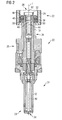
- Figure 3 shows a longitudinal section through a second embodiment of the coupling arrangement 22 for coupling the fuel injector 20 to the fuel rail 18.
- the fuel injector cup 24 is in engagement with the fuel inlet portion 28 of the fuel injector 20.
- the coupling arrangement 22 comprises the fuel injector cup 24, the housing 26 of the fuel injector 20, the back-up ring 36, the separating element 38 and the O-ring seal 40.
- the fuel injector cup 24 has the central longitudinal axis L and is designed to be coupled to the fuel rail 18 at the first axial end area 42 of the fuel injector cup 24 and to the housing 26 of the fuel injector 20 at the second axial end area 44 of the fuel injector cup 24.
- the housing 26 of the fuel injector 20 is arranged at the central longitudinal axis L facing the second axial end area 44 of the fuel injector cup 24.
- the housing 26 of the fuel injector 20 comprises the first part 52 of the housing 26 facing the fuel injector cup 24 and the second part 54 of the housing 26 facing away from the fuel injector cup 24, wherein the first part 52 of the housing 26 comprises a smaller outer diameter than the second part 54 of the housing 26.
- the O-ring seal 40 is arranged between the housing 26 and the fuel injector cup 24 at an axially overlapping area of the fuel injector cup 24 and the housing 26 in order to have a proper sealing between the housing 26 of the fuel injector 20 and the fuel injector cup 24.
- the O-ring seal 40, the separating element 38 and the back-up ring 36 are arranged at least partly circumferentially the first part 52 of the housing 26.
- the separating element 38 is arranged between the O-ring seal 40 and the back-up ring 36 such as to prevent a contact of the O-ring seal 40 with the back-up ring 36.
- the separating element 38 may support the placement of the O-ring seal 40 at the housing 26.
- the back-up ring 36 is in contact with at least a part of the second part 54 of the housing 26 such as to prevent the back-up ring 36 and therewith the O-ring seal 40 and the separating element 38 to be released from the first part 52 of the housing 26.
- a movement of the O-ring seal 40, the separating element 38 and the back-up ring 36 relative to the housing 26 of the fuel injector 20 at least in one direction of the central longitudinal axis L may be prevented.
- the O-ring seal 40, the back-up ring 36 and the separating element 38 may be designed and arranged such as to enable a coupling of the housing 26 of the fuel injector 20 to the fuel injector cup 24 at the second axial end area 44 of the fuel injector cup 24.
- the separating element 38 may comprise plastic.
- the separating element 38 may comprise polytetrafluoroethylene.
- the separating element 38 may comprise Teflon.
- the back-up ring 36 may comprise a larger outer diameter at a first axial end area 46 of the back-up ring 36 facing the separating element 38 than at a second axial end area 48 of the back-up ring 36 facing away from the separating element 38.
- an angled cut of the back-up ring 36 may help the progressive adaption of the support of the O-ring seal 40 while pressure is increasing.
- the separating element 38 comprises a larger outer diameter than the back-up ring 36.
- a wearing and damage caused by a contact between the back-up ring 36, for example a metallic back-up ring 36, and the fuel injector cup 24 may be prevented.
- the back-up ring 36 is shifted over the housing 26 of the fuel injector 20 and arranged at least partly circumferentially the first part 52 of the housing 26 being in contact with the second part 54 of the housing 26.
- the separating element 38 is arranged at least partly circumferentially the first part 52 of the housing 26 being in contact with the back-up ring 36.
- the O-ring seal 40 is arranged at least partly circumferentially the first part 52 of the housing 26 being in contact with the separating element 38.
- the housing 26 of the fuel injector 20 is engaged into the fuel injector cup 24 in such a way that the O-ring seal 40 is arranged between the housing 26 and the fuel injector cup 24 at an axially overlapping area of the fuel injector cup 24 and the housing 26 in order to have a proper sealing between the housing 26 of the fuel injector 20 and the fuel injector cup 24.
- the O-ring seal 40 may be removed and the housing 26 of the fuel injector 20 can be shifted away from the fuel injector cup 24 in axial direction and the fuel injector cup 24 and the fuel injector 20 can be separated from each other.
- the fuel injector cup 24, the back-up ring 36 and the separating element 38 may comprise alternative shapes.
- the housing 26 of the fuel injector 20 may comprise alternative shapes.
Landscapes
- Engineering & Computer Science (AREA)
- Chemical & Material Sciences (AREA)
- Combustion & Propulsion (AREA)
- Mechanical Engineering (AREA)
- General Engineering & Computer Science (AREA)
- Fuel-Injection Apparatus (AREA)
Priority Applications (2)
| Application Number | Priority Date | Filing Date | Title |
|---|---|---|---|
| EP08007858A EP2112367B1 (fr) | 2008-04-23 | 2008-04-23 | Agencement de couplage et injecteur de carburant |
| US12/421,802 US8069841B2 (en) | 2008-04-23 | 2009-04-10 | Coupling arrangement and fuel injector |
Applications Claiming Priority (1)
| Application Number | Priority Date | Filing Date | Title |
|---|---|---|---|
| EP08007858A EP2112367B1 (fr) | 2008-04-23 | 2008-04-23 | Agencement de couplage et injecteur de carburant |
Publications (2)
| Publication Number | Publication Date |
|---|---|
| EP2112367A1 true EP2112367A1 (fr) | 2009-10-28 |
| EP2112367B1 EP2112367B1 (fr) | 2011-09-14 |
Family
ID=39720457
Family Applications (1)
| Application Number | Title | Priority Date | Filing Date |
|---|---|---|---|
| EP08007858A Ceased EP2112367B1 (fr) | 2008-04-23 | 2008-04-23 | Agencement de couplage et injecteur de carburant |
Country Status (2)
| Country | Link |
|---|---|
| US (1) | US8069841B2 (fr) |
| EP (1) | EP2112367B1 (fr) |
Cited By (2)
| Publication number | Priority date | Publication date | Assignee | Title |
|---|---|---|---|---|
| US8479710B2 (en) | 2010-05-07 | 2013-07-09 | Continental Automotive Systems Us, Inc. | Injector to fuel rail coupling structure for high pressure direct injection engines |
| WO2015067389A1 (fr) * | 2013-11-06 | 2015-05-14 | Robert Bosch Gmbh | Vanne de dosage de fluide à haute pression |
Families Citing this family (3)
| Publication number | Priority date | Publication date | Assignee | Title |
|---|---|---|---|---|
| US11174825B2 (en) * | 2019-02-11 | 2021-11-16 | Caterpillar Inc. | Seal configuration for fuel injector |
| DE102019216587A1 (de) * | 2019-10-29 | 2021-04-29 | Robert Bosch Gmbh | Brennstoffeinspritzventil |
| US11454200B2 (en) * | 2019-11-08 | 2022-09-27 | Delphi Technologies Ip Limited | Fuel system with an arrangement which seals between a fuel injector and a fuel rail socket |
Citations (3)
| Publication number | Priority date | Publication date | Assignee | Title |
|---|---|---|---|---|
| US6419282B1 (en) | 2000-08-09 | 2002-07-16 | Siemens Automotive Corporation | Compliant zero evaporative fuel connection |
| WO2006063689A1 (fr) | 2004-12-18 | 2006-06-22 | Daimlerchrysler Ag | Dispositif d'injection de carburant haute pression pour moteur a combustion interne |
| EP1849995A1 (fr) * | 2006-04-24 | 2007-10-31 | Siemens Aktiengesellschaft | Agencement pour monter une soupape d'injection dans une rampe d'injection de carburant |
Family Cites Families (6)
| Publication number | Priority date | Publication date | Assignee | Title |
|---|---|---|---|---|
| DE19725076A1 (de) * | 1997-06-13 | 1998-12-17 | Bosch Gmbh Robert | Brennstoffeinspritzanlage |
| DE10056038A1 (de) * | 2000-11-11 | 2002-05-16 | Bosch Gmbh Robert | Brennstoffeinspritzanlage |
| DE10056005A1 (de) * | 2000-11-11 | 2002-05-16 | Bosch Gmbh Robert | Brennstoffeinspritzanlage |
| US6640784B1 (en) * | 2002-10-09 | 2003-11-04 | Robert Bosch Corporation | Spark ignition direct injection system |
| US20090013968A1 (en) * | 2007-07-09 | 2009-01-15 | Keegan Kevin R | Vapor recovery system for a direct injector fuel rail assembly |
| US7556022B1 (en) * | 2008-01-04 | 2009-07-07 | Millennium Industries | Attachment for fuel injectors in direct injection fuel systems |
-
2008
- 2008-04-23 EP EP08007858A patent/EP2112367B1/fr not_active Ceased
-
2009
- 2009-04-10 US US12/421,802 patent/US8069841B2/en not_active Expired - Fee Related
Patent Citations (3)
| Publication number | Priority date | Publication date | Assignee | Title |
|---|---|---|---|---|
| US6419282B1 (en) | 2000-08-09 | 2002-07-16 | Siemens Automotive Corporation | Compliant zero evaporative fuel connection |
| WO2006063689A1 (fr) | 2004-12-18 | 2006-06-22 | Daimlerchrysler Ag | Dispositif d'injection de carburant haute pression pour moteur a combustion interne |
| EP1849995A1 (fr) * | 2006-04-24 | 2007-10-31 | Siemens Aktiengesellschaft | Agencement pour monter une soupape d'injection dans une rampe d'injection de carburant |
Cited By (5)
| Publication number | Priority date | Publication date | Assignee | Title |
|---|---|---|---|---|
| US8479710B2 (en) | 2010-05-07 | 2013-07-09 | Continental Automotive Systems Us, Inc. | Injector to fuel rail coupling structure for high pressure direct injection engines |
| WO2015067389A1 (fr) * | 2013-11-06 | 2015-05-14 | Robert Bosch Gmbh | Vanne de dosage de fluide à haute pression |
| JP2016538474A (ja) * | 2013-11-06 | 2016-12-08 | ローベルト ボッシュ ゲゼルシャフト ミット ベシュレンクテル ハフツング | 高圧下にある流体を調量するための弁 |
| US10378653B2 (en) | 2013-11-06 | 2019-08-13 | Robert Bosch Gmbh | Valve for the metering of highly pressurized fluid |
| DE102013222508B4 (de) | 2013-11-06 | 2023-07-27 | Robert Bosch Gmbh | Ventil zum Zumessen von unter Hochdruck stehendem Fluid |
Also Published As
| Publication number | Publication date |
|---|---|
| US20090308954A1 (en) | 2009-12-17 |
| US8069841B2 (en) | 2011-12-06 |
| EP2112367B1 (fr) | 2011-09-14 |
Similar Documents
| Publication | Publication Date | Title |
|---|---|---|
| EP2093413B1 (fr) | Dispositif de couplage | |
| EP2103804B1 (fr) | Agencement de couplage | |
| EP2093412B1 (fr) | Dispositif de couplage | |
| US7976073B2 (en) | Coupling device | |
| US7934488B2 (en) | Coupling device | |
| EP2241746A1 (fr) | Dispositif de couplage | |
| EP2375052B1 (fr) | Ensemble d'injecteur de carburant | |
| US8069841B2 (en) | Coupling arrangement and fuel injector | |
| US8245697B2 (en) | Coupling device | |
| EP3088728B1 (fr) | Pompe à carburant destinée à un système d'injection directe avec une étanchéité hydraulique ameliorée de la soupape d'admission | |
| EP2246555B1 (fr) | Dispositif de couplage et agencement d'injection de carburant | |
| EP2058509A1 (fr) | Raccord | |
| US8171917B2 (en) | Coupling device | |
| EP2141348B1 (fr) | Ensemble injecteur de fluides | |
| US7886718B2 (en) | Fuel injector having integral body guide and nozzle case for pressure containment | |
| EP2090772B1 (fr) | Ensemble de couplage | |
| US10018168B2 (en) | Fuel injector and fuel-injection system | |
| JP6358162B2 (ja) | 燃料供給システム | |
| EP1600626A1 (fr) | Système de raccordement | |
| EP1876349A1 (fr) | Dispositif d'injection pour un injecteur |
Legal Events
| Date | Code | Title | Description |
|---|---|---|---|
| PUAI | Public reference made under article 153(3) epc to a published international application that has entered the european phase |
Free format text: ORIGINAL CODE: 0009012 |
|
| AK | Designated contracting states |
Kind code of ref document: A1 Designated state(s): AT BE BG CH CY CZ DE DK EE ES FI FR GB GR HR HU IE IS IT LI LT LU LV MC MT NL NO PL PT RO SE SI SK TR |
|
| AX | Request for extension of the european patent |
Extension state: AL BA MK RS |
|
| 17P | Request for examination filed |
Effective date: 20100428 |
|
| AKX | Designation fees paid |
Designated state(s): DE FR IT |
|
| GRAP | Despatch of communication of intention to grant a patent |
Free format text: ORIGINAL CODE: EPIDOSNIGR1 |
|
| GRAS | Grant fee paid |
Free format text: ORIGINAL CODE: EPIDOSNIGR3 |
|
| GRAA | (expected) grant |
Free format text: ORIGINAL CODE: 0009210 |
|
| RIN1 | Information on inventor provided before grant (corrected) |
Inventor name: GIORGETTI, EDOARDO Inventor name: GRANDI, MAURO |
|
| AK | Designated contracting states |
Kind code of ref document: B1 Designated state(s): DE FR IT |
|
| REG | Reference to a national code |
Ref country code: DE Ref legal event code: R096 Ref document number: 602008009697 Country of ref document: DE Effective date: 20111124 |
|
| PLBE | No opposition filed within time limit |
Free format text: ORIGINAL CODE: 0009261 |
|
| STAA | Information on the status of an ep patent application or granted ep patent |
Free format text: STATUS: NO OPPOSITION FILED WITHIN TIME LIMIT |
|
| 26N | No opposition filed |
Effective date: 20120615 |
|
| REG | Reference to a national code |
Ref country code: DE Ref legal event code: R097 Ref document number: 602008009697 Country of ref document: DE Effective date: 20120615 |
|
| REG | Reference to a national code |
Ref country code: FR Ref legal event code: PLFP Year of fee payment: 9 |
|
| REG | Reference to a national code |
Ref country code: FR Ref legal event code: PLFP Year of fee payment: 10 |
|
| REG | Reference to a national code |
Ref country code: FR Ref legal event code: PLFP Year of fee payment: 11 |
|
| PGFP | Annual fee paid to national office [announced via postgrant information from national office to epo] |
Ref country code: DE Payment date: 20180430 Year of fee payment: 11 |
|
| PGFP | Annual fee paid to national office [announced via postgrant information from national office to epo] |
Ref country code: IT Payment date: 20190429 Year of fee payment: 12 |
|
| PGFP | Annual fee paid to national office [announced via postgrant information from national office to epo] |
Ref country code: FR Payment date: 20190424 Year of fee payment: 12 |
|
| REG | Reference to a national code |
Ref country code: DE Ref legal event code: R119 Ref document number: 602008009697 Country of ref document: DE |
|
| PG25 | Lapsed in a contracting state [announced via postgrant information from national office to epo] |
Ref country code: DE Free format text: LAPSE BECAUSE OF NON-PAYMENT OF DUE FEES Effective date: 20191101 |
|
| REG | Reference to a national code |
Ref country code: DE Ref legal event code: R081 Ref document number: 602008009697 Country of ref document: DE Owner name: VITESCO TECHNOLOGIES GMBH, DE Free format text: FORMER OWNER: CONTINENTAL AUTOMOTIVE GMBH, 30165 HANNOVER, DE |
|
| PG25 | Lapsed in a contracting state [announced via postgrant information from national office to epo] |
Ref country code: FR Free format text: LAPSE BECAUSE OF NON-PAYMENT OF DUE FEES Effective date: 20200430 |
|
| PG25 | Lapsed in a contracting state [announced via postgrant information from national office to epo] |
Ref country code: IT Free format text: LAPSE BECAUSE OF NON-PAYMENT OF DUE FEES Effective date: 20200423 |