EP2112381A2 - Dispositif ventilateur - Google Patents
Dispositif ventilateur Download PDFInfo
- Publication number
- EP2112381A2 EP2112381A2 EP09003504A EP09003504A EP2112381A2 EP 2112381 A2 EP2112381 A2 EP 2112381A2 EP 09003504 A EP09003504 A EP 09003504A EP 09003504 A EP09003504 A EP 09003504A EP 2112381 A2 EP2112381 A2 EP 2112381A2
- Authority
- EP
- European Patent Office
- Prior art keywords
- fan
- circuit board
- small
- fastening part
- housing
- Prior art date
- Legal status (The legal status is an assumption and is not a legal conclusion. Google has not performed a legal analysis and makes no representation as to the accuracy of the status listed.)
- Withdrawn
Links
- 239000013013 elastic material Substances 0.000 claims abstract description 4
- 238000004804 winding Methods 0.000 claims description 7
- 229920001971 elastomer Polymers 0.000 abstract description 2
- 239000000806 elastomer Substances 0.000 abstract description 2
- 239000012528 membrane Substances 0.000 description 10
- 239000000725 suspension Substances 0.000 description 9
- 210000002105 tongue Anatomy 0.000 description 7
- 230000006378 damage Effects 0.000 description 4
- 238000013016 damping Methods 0.000 description 4
- 239000006260 foam Substances 0.000 description 3
- 238000012986 modification Methods 0.000 description 3
- 230000004048 modification Effects 0.000 description 3
- 238000005476 soldering Methods 0.000 description 3
- 238000011161 development Methods 0.000 description 2
- 230000018109 developmental process Effects 0.000 description 2
- 238000010438 heat treatment Methods 0.000 description 2
- 238000007664 blowing Methods 0.000 description 1
- 238000001816 cooling Methods 0.000 description 1
- 230000001419 dependent effect Effects 0.000 description 1
- 238000003780 insertion Methods 0.000 description 1
- 230000037431 insertion Effects 0.000 description 1
- 238000009423 ventilation Methods 0.000 description 1
Images






Classifications
-
- F—MECHANICAL ENGINEERING; LIGHTING; HEATING; WEAPONS; BLASTING
- F04—POSITIVE - DISPLACEMENT MACHINES FOR LIQUIDS; PUMPS FOR LIQUIDS OR ELASTIC FLUIDS
- F04D—NON-POSITIVE-DISPLACEMENT PUMPS
- F04D25/00—Pumping installations or systems
- F04D25/02—Units comprising pumps and their driving means
- F04D25/06—Units comprising pumps and their driving means the pump being electrically driven
- F04D25/0606—Units comprising pumps and their driving means the pump being electrically driven the electric motor being specially adapted for integration in the pump
- F04D25/0613—Units comprising pumps and their driving means the pump being electrically driven the electric motor being specially adapted for integration in the pump the electric motor being of the inside-out type, i.e. the rotor is arranged radially outside a central stator
- F04D25/0633—Details of the magnetic circuit
-
- F—MECHANICAL ENGINEERING; LIGHTING; HEATING; WEAPONS; BLASTING
- F04—POSITIVE - DISPLACEMENT MACHINES FOR LIQUIDS; PUMPS FOR LIQUIDS OR ELASTIC FLUIDS
- F04D—NON-POSITIVE-DISPLACEMENT PUMPS
- F04D25/00—Pumping installations or systems
- F04D25/02—Units comprising pumps and their driving means
- F04D25/06—Units comprising pumps and their driving means the pump being electrically driven
- F04D25/0606—Units comprising pumps and their driving means the pump being electrically driven the electric motor being specially adapted for integration in the pump
- F04D25/0613—Units comprising pumps and their driving means the pump being electrically driven the electric motor being specially adapted for integration in the pump the electric motor being of the inside-out type, i.e. the rotor is arranged radially outside a central stator
- F04D25/0646—Details of the stator
-
- F—MECHANICAL ENGINEERING; LIGHTING; HEATING; WEAPONS; BLASTING
- F04—POSITIVE - DISPLACEMENT MACHINES FOR LIQUIDS; PUMPS FOR LIQUIDS OR ELASTIC FLUIDS
- F04D—NON-POSITIVE-DISPLACEMENT PUMPS
- F04D25/00—Pumping installations or systems
- F04D25/02—Units comprising pumps and their driving means
- F04D25/06—Units comprising pumps and their driving means the pump being electrically driven
- F04D25/068—Mechanical details of the pump control unit
-
- F—MECHANICAL ENGINEERING; LIGHTING; HEATING; WEAPONS; BLASTING
- F04—POSITIVE - DISPLACEMENT MACHINES FOR LIQUIDS; PUMPS FOR LIQUIDS OR ELASTIC FLUIDS
- F04D—NON-POSITIVE-DISPLACEMENT PUMPS
- F04D25/00—Pumping installations or systems
- F04D25/02—Units comprising pumps and their driving means
- F04D25/06—Units comprising pumps and their driving means the pump being electrically driven
- F04D25/0693—Details or arrangements of the wiring
-
- F—MECHANICAL ENGINEERING; LIGHTING; HEATING; WEAPONS; BLASTING
- F04—POSITIVE - DISPLACEMENT MACHINES FOR LIQUIDS; PUMPS FOR LIQUIDS OR ELASTIC FLUIDS
- F04D—NON-POSITIVE-DISPLACEMENT PUMPS
- F04D29/00—Details, component parts, or accessories
- F04D29/60—Mounting; Assembling; Disassembling
- F04D29/601—Mounting; Assembling; Disassembling specially adapted for elastic fluid pumps
-
- F—MECHANICAL ENGINEERING; LIGHTING; HEATING; WEAPONS; BLASTING
- F04—POSITIVE - DISPLACEMENT MACHINES FOR LIQUIDS; PUMPS FOR LIQUIDS OR ELASTIC FLUIDS
- F04D—NON-POSITIVE-DISPLACEMENT PUMPS
- F04D29/00—Details, component parts, or accessories
- F04D29/66—Combating cavitation, whirls, noise, vibration or the like; Balancing
- F04D29/661—Combating cavitation, whirls, noise, vibration or the like; Balancing especially adapted for elastic fluid pumps
- F04D29/668—Combating cavitation, whirls, noise, vibration or the like; Balancing especially adapted for elastic fluid pumps damping or preventing mechanical vibrations
Definitions
- the invention relates to a small fan assembly and, in particular, a small fan assembly with a vibration-damping suspension.
- small or very small fans with housing dimensions of 20 to 60 mm side length are used for the realization of such fan arrangements.
- These often have to be provided with application-specific advanced driving and protection electronics suitable for cooling or, in conjunction with a small heating, for heating tasks, e.g. in automobiles, trains, airplanes, control boxes, cabinets and IT electronics cabinets is required.
- this electronics can also be designed to operate the fan alternatively blowing or sucking. Due to the very small dimensions of small and micro fans, however, the extended control and protection electronics are usually not or only partially arranged on the circuit board associated with the fan.
- a small fan assembly according to claim 1.
- an additional mounting surface is provided by the use of a second circuit board, which is arranged radially within an outer fastening part and outside a fan housing of the fan.
- the dimensions of the second printed circuit board are in this case preferably determined as a function of the dimensions of the fan housing and the fastening part, so that their dimensions can remain unchanged small.
- the additional mounting surface is provided by the use of a second circuit board, which is arranged radially within the fan housing.
- control electronics without compromising the air performance and the air pressure build-up or the performance of the fan can be realized in a simple manner.
- This control electronics can have protection against incorrect polarity connection, overvoltage protection and / or stall protection.
- additional assembly area space for control via pulse width modulation, analog and / or power control, as well as LAN or CAN bus control systems can be created.
- left, right, front, back, top, and bottom refer to the respective drawing figure and may vary from one drawing figure to another depending on a particular orientation (portrait or landscape). Identical or equivalent parts are denoted by the same reference numerals in the various figures and usually described only once.
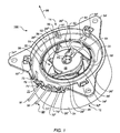
- Fig. 1 shows a first embodiment of a fan assembly 100 with a fan 10 and a mounting portion 34.
- the latter has mounting flanges 34 ', 34 ", 34''' for mounting the fan assembly 100, which screwed over the mounting flanges 34 ', 34", 34''' , riveted, glued or welded.
- the attachment member 34 itself can be foamed directly in wall foams, foam pillows, foam backs, etc.
- the fan 10 has a fan housing 30, in which a fan 18 about an axis of rotation 23 (FIG. Fig. 7 ) is rotatably disposed, which extends along the longitudinal axis of the fan housing 30.
- the fan 18 promotes air in the direction of an arrow 98 during operation of the fan 10 (FIG. Fig. 1 . 7 ) from a suction side 12 to a pressure side 14 of the fan 10, and has fan blades 26 'to 26V, whose shape is adapted to the shape of the inside of the fan housing 30.
- the fan housing 30 is as in Fig. 2 described via a vibration-damping suspension 32 ( Fig. 2 . 7 . 8th ) suspended in the attachment part 34, which is arranged radially outside of the fan housing 30.
- the suspension 32 is used to reduce vibrations occurring during operation of the fan 10 and Schallabstrahlept.
- the fan 10 has a motor 21 (FIG. Fig. 7 to 9 ) for driving its fan wheel 18, which motor 21 is preferably designed as an electronically commutated external rotor motor. He has a rotor bell 25 ( Fig. 2 . 7 . 8th ) to which the fan 18 is attached.
- a motor holding cup 85 mounting flange 38 which is connected via webs 29 '.. 29'' to the fan housing 30.
- the motor 21 is associated with a first circuit board 52 for receiving components of the engine electronics, which first circuit board 52 is disposed within the fan housing 30. It is via flexible connection lines 62, 64 ( Fig. 1 ) Connected to a second circuit board 54, which is provided as an additional mounting surface for advanced control and protection electronics.
- the second printed circuit board 54 is arranged radially inside the fastening part 34 and outside of the fan housing 30.
- the dimensions of the second circuit board 54 are preferably determined depending on the dimensions of the fan housing 30 and the attachment part 34.
- the fan housing 30 is formed tubular by way of example, and the second circuit board 54 is arranged annularly around the tubular fan housing 30.
- the second circuit board 54 may be provided either in the region of the suction side 12 or in the region of the pressure side 14 of the fan 10.
- the use of a single second circuit board 54 which is arranged in the region of the suction side 12 or the pressure side 14 of the fan 10, serves only as an example for illustrating an embodiment of the invention.
- the second circuit board 54 may be provided on the suction side 12 of the fan 10, and a third Printed circuit board is arranged in the region of the pressure side 14, wherein, for example, the second and third circuit board are electrically conductively connected to each other.
- At least one recess 39 is provided, which allows for a closure of the pressure side 14 of the fan 10, a backflow of air conveyed by the fan 18 air from the pressure side 14 to the suction side 12.
- the recess 39 is in Fig. 1 is formed as an annular gap between the second circuit board 54 and the fan housing 30.
- Fig. 1 For fastening the second circuit board 54 in the fastening part 34 are in Fig. 1
- three fastening elements 82 ', 82 ", 82''' are provided, which are formed, for example, as radially resilient latching tongues on the inner side 36 of the fastening part 34.
- this is in Fig. 1 inserted from the pressure side 14 into the fastening part 34, wherein the locking tongues 82 ', 82 ", 82''' are first bent radially outwardly from a predetermined starting position, and then after inserting the second circuit board 54 back to spring back into its original position the circuit board 54.
- this preferably has a guide groove 97, which is guided during insertion into the fastening part 34 along a guide projection 99 provided on the inside 36 of the fastening part.
- the second circuit board 54 may be connected to the first circuit board 52 via lines 62, 64, e.g. by soldering.
- the second circuit board 54 is further electrically connected to a flexible power supply line 90 having two lines 91, 92, e.g. also by soldering. In many cases further lines are provided, e.g. for a tacho signal or an alarm signal.
- a strain relief device 70 is provided on the attachment part 34 for the flexible power supply line 90.
- This has at least one suspension eye 71 ', 71 ", at least one winding pin 72', 72” and at least one hook bolt 73 ', 73 " Winding pin 72 ', 72 “is guided around the hook bolt 73', 73” on the hook bolt 73 ', 73 ", the cable 90 is wound around its entire outer circumference at least once and then guided to the printed circuit board 54, cf.
- a separate strain relief device for each line 91, 92 of the power supply line 90 may be provided. Accordingly, in Fig. 1 a suspension eye 71 ', a winding bolt 72' and a hook bolt 73 'for the line 91, and a suspension eye 71 ", a winding bolt 72" and a hook bolt 73 "provided for the line 92.
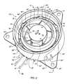
- FIG. 2 shows the suction side 12 of the fan assembly 100 of Fig. 1
- Fig. 2 illustrates the provided on the fastening part 34 latching tongue 82 '''and the vibration-damping suspension 32.
- Fig. 2 Supporting elements 84 ', 84 ", 84''', 84 IV for supporting the second circuit board 54 (FIG. Fig. 1 ).
- the vibration-damping suspension 32 is a diaphragm made of an elastic material, which elastically connects the fan housing 30 and the fastening part 34.
- the membrane 32 is e.g. made of a plastic or an elastomer as a direct connection between the fastening part 34 and the fan housing 30.
- the membrane 32 can be connected to the fan housing 30 and / or the fastening part 34 in a material-locking and / or form-fitting manner. With the fan housing 30, the membrane 32 is almost or completely connected to its entire outer periphery. With the fastening part 34, the membrane is almost or completely connected to the entire inner side 36.
- the membrane 32 has six recesses 33 ', 33 ", 33"', 33 IV , 33 V , 33 VI . These serve to allow for a closure of the pressure side 14 of the fan 10, a return flow of air conveyed by the fan 18 of the pressure side 14 to the suction side 12.
- a suitable diaphragm for suspending a fan housing in a mounting part is in the EP 1 498 613 A2 described, which is incorporated herein by reference.
- the support elements 84 ', 84 ", 84''', 84 IV are formed according to an embodiment as axially resilient support members on the inner side 36 of the fastening part 34, on these is the circuit board 54 after mounting in the mounting member 34 resiliently, as below Fig. 7 described.
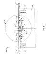
- Fig. 3 shows a side view of the fan assembly 100 of Fig. 1 with the strain relief device 70 and provided on the fastening part 34, resilient locking tongues 82 ", 82"'.
- Fig. 4 shows a greatly enlarged view (scale 5: 1) of the strain relief device 70 of Fig. 3
- Fig. 4 illustrates the in the suspension eyes 71 ', 71''hinged, around the winding pins 72', 72 "around and at least once around the entire outer circumference of the hook bolts 73 ', 73" wound lines 91 and 92nd
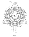
- Fig. 5 shows a plan view of the pressure side 14 of the fan assembly 100 of Fig. 1 , Fig. 5 illustrates the locking of the second circuit board 54 with the radially resilient latching tongues 82 ', 82 ", 82''' in the fastening part 34th
- Fig. 5A show the Fig. 5 in natural size, so in the scale 1: 1.
- Fig. 6 shows a plan view of the suction side 12 of the fan assembly 100 of Fig. 1 ,
- the membrane 32 is connected in a form-fitting manner to the fan housing 30 and the fastening part 34.
- Fig. 6 illustrates the six provided in the membrane 32 recesses 33 ', 33 ", 33"', 33 IV , 33 V , 33 VI and the resilient support members 84 ', 84 ", 84''', 84 IV , 84 V , 84 VI ,
- Fig. 7 shows a sectional view of the fan assembly 100 of Fig. 1 and illustrates the form and materially connected to the fan housing 30 and the mounting member 34 membrane 32, as well as provided on the fastening part 34, resilient support members 84 ", 84 V , on which the second circuit board 54 rests.
- the electronically commutated drive motor 21 has a stator assembly 83 with Klauenpolblechen 87, an outer rotor 88, and one with the mounting flange 38th
- the rotor 88 has the rotor bell 25, on which the fan 18 is fixed, and a rotor shaft 86 which is rotatably mounted in a bearing assembly 60 about the rotation axis 23.
- Fig. 8 shows a sectional view of the fan assembly 100 of Fig. 1
- Fig. 8 illustrates the attachment of the second circuit board 54 in the attachment part 34 and the connection of the electrical connection line 64 to the first and second circuit board 52 and 54, respectively.
- the second circuit board 54 rests with its underside 54 'on the resilient support members 84 ", 84 IV and is locked at its upper side 54".
- the latching tongue 82 ' has for this purpose a latching hook 95, which engages on the upper side 54 "of the printed circuit board 54.
- an electrical connection 64 ' is provided, to which one end of the connection line 64 is fastened, the other end of which is connected to an electrical connection 64" provided on the first circuit board 52.
- the length of the lead 64 is chosen in consideration of the spring travel of the diaphragm 32 to prevent damage or destruction of the electrical connection between the circuit boards 52, 54 during operation of the fan 10, e.g. by tearing off the line 64, to prevent.
- Fig. 9 shows a greatly enlarged view of the drive motor 21 of Fig. 8 and shows the line 64 connected to the electrical connection 64 "provided on the first circuit board 52.
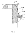
- Fig. 10 shows a greatly enlarged view of the resilient latching tongue 82 'of Fig. 8 , which with its latched at the top 54 "of the circuit board 54 latching hooks 95, the circuit board 54 in the fastening part 34.
- a game D is present, with which possible movements of the second circuit board 54 in Operation of the fan 10 ( Fig. 1 ).
- Fig. 11 13 shows a second embodiment of a fan assembly 200 having a fan 110 and a mounting member 134 having mounting flanges 134 ', 134 ", 134''' for mounting the fan assembly 200.
- the fan 110 like the fan 10 of the first embodiment, has a fan housing 30, in which the fan 18 about the axis of rotation 23 ( Fig. 12 . 13 ) is rotatably mounted, which promotes air in the direction of the arrow 98 from the suction side 12 to the pressure side 14 of the fan 110 during operation of the fan 10 with its fan blades 26 'to 26V.
- the fan housing 30 is suspended over the membrane 32 in the attachment part 34.
- the fan 110 has a motor 121 (preferably designed as an electronically commutated external rotor motor) 121 (FIG. Fig. 12 and 13 ) to drive its fan wheel 18.
- This has a rotor bell 25 ( Fig. 12 ) to which the fan 18 is attached.
- For mounting the motor 121 in the fan housing 30 is provided on a motor holding shell 185 mounting flange 38 which is connected via webs 129 'to 129''' to the fan housing 30.
- the engine support shell 185 differs from the engine support shell 85 of the first embodiment, as below Fig. 12 described.
- the motor 121 is associated with the first circuit board 52, which is disposed within the fan housing 30.
- the first printed circuit board 52 is connected via a connecting line 148 (FIG. Fig. 12 and 13 ) electrically conductively connected to a second printed circuit board 154 (FIG. Fig. 12 and 13 ), which is also located inside the fan housing 30, as shown below Fig. 12 and 13 described.
- a flexible power supply line 190 For supplying an operating voltage for the motor 121 is in Fig. 11 the first circuit board 52 by a flexible power supply line 190, which has two lines 191, 192, electrically conductively connected, for example by soldering, wherein further lines may be provided, for example for a speed signal or an alarm signal.
- a strain relief device 170 is provided on the attachment part 134. This essentially corresponds to the strain relief device 70 of the first embodiment, but in which the hook bolts 73 ', 73 "were dispensed with.
- Fig. 12 shows a sectional view of the fan assembly 200 of Fig. 11 , which illustrates the diaphragm 32 connected to the fan housing 30 and the fastening part 134.
- the engine 121 corresponds substantially to the above at Fig. 7
- the motor holding cup 185 compared to the motor holding cup 85 of the first embodiment has a greater height and thus a larger interior, in which a second circuit board 154 is arranged.
- a second circuit board 154 is arranged. This is in Fig. 12 on a bearing tube 149 of Motor holding shell 185 stored.
- the second circuit board 154 is electrically conductively connected to the first circuit board 52.
- the lead 148 is preferably a contact pin.
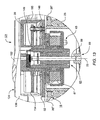
- Fig. 13 shows a greatly enlarged view of the drive motor 121 of the Fig. 12 , It shows the electrically conductive connection between the first and second printed circuit boards 52 and 154 via the contact pin 148.
Landscapes
- Engineering & Computer Science (AREA)
- Mechanical Engineering (AREA)
- General Engineering & Computer Science (AREA)
- Structures Of Non-Positive Displacement Pumps (AREA)
- Motor Or Generator Frames (AREA)
Applications Claiming Priority (1)
| Application Number | Priority Date | Filing Date | Title |
|---|---|---|---|
| DE202008005917 | 2008-04-21 |
Publications (2)
| Publication Number | Publication Date |
|---|---|
| EP2112381A2 true EP2112381A2 (fr) | 2009-10-28 |
| EP2112381A3 EP2112381A3 (fr) | 2014-04-30 |
Family
ID=40475017
Family Applications (1)
| Application Number | Title | Priority Date | Filing Date |
|---|---|---|---|
| EP09003504.9A Withdrawn EP2112381A3 (fr) | 2008-04-21 | 2009-03-11 | Dispositif ventilateur |
Country Status (3)
| Country | Link |
|---|---|
| US (1) | US8371830B2 (fr) |
| EP (1) | EP2112381A3 (fr) |
| DE (1) | DE202009004586U1 (fr) |
Cited By (1)
| Publication number | Priority date | Publication date | Assignee | Title |
|---|---|---|---|---|
| US12213553B2 (en) | 2020-10-13 | 2025-02-04 | Gilz Llc | Head protection with integrated air filtration |
Families Citing this family (20)
| Publication number | Priority date | Publication date | Assignee | Title |
|---|---|---|---|---|
| USD639924S1 (en) * | 2008-01-25 | 2011-06-14 | Ebm-Papst St. Georgen Gmbh & Co. Kg | Axial fan |
| DE102010045899B3 (de) | 2010-09-17 | 2012-02-16 | Ingo Schehr | Ventilatoreinheit mit einem elektrischen Axialventilator |
| US9121414B2 (en) | 2010-11-05 | 2015-09-01 | Gentherm Incorporated | Low-profile blowers and methods |
| USD703301S1 (en) * | 2011-08-08 | 2014-04-22 | Ebm-Papst St. Georgen Gmbh & Co. Kg | Axial fan |
| DE102011114933B9 (de) * | 2011-10-06 | 2019-03-07 | I.G. Bauerhin Gmbh | "Sitzgestell für einen Fahrzeugsitz" |
| USD701299S1 (en) * | 2012-09-21 | 2014-03-18 | Asmo Co., Ltd. | Fan motor |
| CN103790866B (zh) * | 2012-10-31 | 2016-05-11 | 英业达科技有限公司 | 风扇结构 |
| TWI542792B (zh) * | 2013-07-17 | 2016-07-21 | 建準電機工業股份有限公司 | 減震風扇 |
| TWI542789B (zh) * | 2013-07-17 | 2016-07-21 | 建準電機工業股份有限公司 | 串聯式風扇 |
| WO2015171901A1 (fr) | 2014-05-09 | 2015-11-12 | Gentherm Incorporated | Ensemble de régulation de la température |
| DE102014111055A1 (de) * | 2014-08-04 | 2016-02-04 | Ebm-Papst St. Georgen Gmbh & Co. Kg | Lüftereinheit mit einem Axiallüfter |
| CH713428A2 (de) * | 2018-06-06 | 2018-08-15 | V Zug Ag | Kühlgerät mit aktiver Luftumwälzung. |
| CN121230238A (zh) | 2018-11-30 | 2025-12-30 | 金瑟姆股份公司 | 热电调节系统和方法 |
| JP7327045B2 (ja) * | 2019-09-26 | 2023-08-16 | ニデック株式会社 | 送風機 |
| JP2021065463A (ja) * | 2019-10-24 | 2021-04-30 | 株式会社マキタ | 集塵機 |
| US20210289876A1 (en) * | 2020-03-20 | 2021-09-23 | Hall Labs Llc | Personal Air Filtration Device with Reduced Noise from Air Mover |
| US12611909B2 (en) | 2021-03-18 | 2026-04-28 | Gentherm Incorporated | Preconditioning surfaces using intelligent thermal effectors |
| US12552223B2 (en) | 2021-03-18 | 2026-02-17 | Gentherm Incorporated | Optimal control of convective thermal devices |
| JP2024132250A (ja) * | 2023-03-17 | 2024-09-30 | 山洋電気株式会社 | 軸流送風機 |
| US12431763B1 (en) * | 2024-05-09 | 2025-09-30 | Whisper Aero Inc. | Conductive aerodynamic stator |
Citations (1)
| Publication number | Priority date | Publication date | Assignee | Title |
|---|---|---|---|---|
| EP1498613A2 (fr) | 2003-07-15 | 2005-01-19 | Papst-Motoren GmbH & Co. KG | Ensemble ventilateur et sa méthode de fabrication |
Family Cites Families (10)
| Publication number | Priority date | Publication date | Assignee | Title |
|---|---|---|---|---|
| US4171190A (en) | 1976-11-08 | 1979-10-16 | Molded Products Company | Blower motor mounting assembly |
| US4170190A (en) * | 1978-04-04 | 1979-10-09 | Warner John H | Method for detecting and a detector for indicating excessive temperature at electrical wiring devices |
| US4385025A (en) | 1979-10-22 | 1983-05-24 | Barry Wright Corporation | Method of coinjection molding of thermoplastic and thermoplastic elastomer |
| US4568243A (en) | 1981-10-08 | 1986-02-04 | Barry Wright Corporation | Vibration isolating seal for mounting fans and blowers |
| DE3227017A1 (de) | 1982-07-20 | 1984-01-26 | Bayer Ag, 5090 Leverkusen | Verfahren zur herstellung von kunststoffen aus polyisocyanat-basis |
| DE3823477A1 (de) | 1988-07-11 | 1990-01-18 | Siemens Ag | Verfahren zur fertigung von ultraschall-wandlern |
| DE3927426B4 (de) | 1989-08-19 | 2006-02-23 | Ebm-Papst Mulfingen Gmbh & Co. Kg | Antriebseinheit für eine Wäsche-Behandlungsmaschine |
| DE29914693U1 (de) * | 1998-09-01 | 2000-01-13 | Papst Motoren Gmbh & Co Kg | Axiallüfter mit einem Aussenläufer-Antriebsmotor |
| JP2001128432A (ja) * | 1999-09-10 | 2001-05-11 | Jianzhun Electric Mach Ind Co Ltd | 交流電源駆動式直流ブラシレス電動機 |
| EP1464106A1 (fr) * | 2002-01-11 | 2004-10-06 | ebm-papst St. Georgen GmbH & Co. KG | Ventilateur miniature ou micro-ventilateur |
-
2009
- 2009-03-11 EP EP09003504.9A patent/EP2112381A3/fr not_active Withdrawn
- 2009-04-03 DE DE202009004586U patent/DE202009004586U1/de not_active Expired - Lifetime
- 2009-04-16 US US12/424,554 patent/US8371830B2/en not_active Expired - Fee Related
Patent Citations (1)
| Publication number | Priority date | Publication date | Assignee | Title |
|---|---|---|---|---|
| EP1498613A2 (fr) | 2003-07-15 | 2005-01-19 | Papst-Motoren GmbH & Co. KG | Ensemble ventilateur et sa méthode de fabrication |
Cited By (1)
| Publication number | Priority date | Publication date | Assignee | Title |
|---|---|---|---|---|
| US12213553B2 (en) | 2020-10-13 | 2025-02-04 | Gilz Llc | Head protection with integrated air filtration |
Also Published As
| Publication number | Publication date |
|---|---|
| US8371830B2 (en) | 2013-02-12 |
| DE202009004586U1 (de) | 2009-09-10 |
| US20090263242A1 (en) | 2009-10-22 |
| EP2112381A3 (fr) | 2014-04-30 |
Similar Documents
| Publication | Publication Date | Title |
|---|---|---|
| EP2112381A2 (fr) | Dispositif ventilateur | |
| EP2083176B1 (fr) | Unité de ventilateur dotée d'un ventilateur axial | |
| DE19503521B4 (de) | Lüfter mit einem Lüfterrad | |
| EP1464106A1 (fr) | Ventilateur miniature ou micro-ventilateur | |
| EP1702165A1 (fr) | Dispositif pour refroidir une carte de circuits ou similaire | |
| CH669486A5 (fr) | ||
| DE102005016043A1 (de) | Aufbau zum Montieren eines Akkukastens auf einem elektrischen Fahrrad | |
| DE102009007803A1 (de) | Mehrflügel-Zentrifugalventilator | |
| DE102022103847A1 (de) | Motor und antriebselement | |
| WO2015106881A1 (fr) | Système modulaire pour un dispositif d'évaporation d'une installation de climatisation montée sur un toit | |
| DE112013006947T5 (de) | Rotor-Haltestruktur einer elektrischen Umlaufmaschine für Hybridfahrzeuge | |
| DE202010017072U1 (de) | Vorrichtung zum Halten eines Bauteils auf einer Leiterplatte | |
| EP2603388B1 (fr) | Système de ventilation | |
| DE102015105894A1 (de) | Elektrisches Gebläse | |
| WO2005026510A1 (fr) | Module d'aeration | |
| EP1000783A1 (fr) | Ventilateur radial avec raccord de connexion | |
| EP1117155A1 (fr) | Fixation et montage d'un connecteur à angle droit sur un circuit imprimé | |
| DE102008048835A1 (de) | Fixierungssystem zum lösbaren Fixieren einer Lichtquelle an einer Lichteintrittsfläche eines Lichtleitkörpers | |
| DE112023003174T5 (de) | Elektrisch angetriebener verdichter | |
| EP0548611A1 (fr) | Moteur électrique avec génératrice tachymétrique | |
| EP0168744A2 (fr) | Flasque-palier pour micromoteurs à courant continu | |
| DE102011005058A1 (de) | Elektromotoranordnung und Verfahren zum Montieren einer Elektromotoranordnung | |
| DE202010006891U1 (de) | Gerätelüfter | |
| EP2439834A2 (fr) | Boîtier d'engrenage, agencement d'engrenage de moteur et entraînement d'essuie-glace | |
| EP2486348B1 (fr) | Appareil de réfrigération doté d'un bloc ventilateur |
Legal Events
| Date | Code | Title | Description |
|---|---|---|---|
| PUAI | Public reference made under article 153(3) epc to a published international application that has entered the european phase |
Free format text: ORIGINAL CODE: 0009012 |
|
| AK | Designated contracting states |
Kind code of ref document: A2 Designated state(s): AT BE BG CH CY CZ DE DK EE ES FI FR GB GR HR HU IE IS IT LI LT LU LV MC MK MT NL NO PL PT RO SE SI SK TR |
|
| AX | Request for extension of the european patent |
Extension state: AL BA RS |
|
| PUAL | Search report despatched |
Free format text: ORIGINAL CODE: 0009013 |
|
| AK | Designated contracting states |
Kind code of ref document: A3 Designated state(s): AT BE BG CH CY CZ DE DK EE ES FI FR GB GR HR HU IE IS IT LI LT LU LV MC MK MT NL NO PL PT RO SE SI SK TR |
|
| AX | Request for extension of the european patent |
Extension state: AL BA RS |
|
| RIC1 | Information provided on ipc code assigned before grant |
Ipc: F04D 25/06 20060101AFI20140327BHEP Ipc: F04D 29/60 20060101ALI20140327BHEP Ipc: F04D 29/64 20060101ALI20140327BHEP Ipc: F04D 29/66 20060101ALI20140327BHEP |
|
| STAA | Information on the status of an ep patent application or granted ep patent |
Free format text: STATUS: THE APPLICATION HAS BEEN WITHDRAWN |
|
| 18W | Application withdrawn |
Effective date: 20141029 |