EP2112384B1 - Cheville dotée d'un élément de fixation et d'une douille - Google Patents
Cheville dotée d'un élément de fixation et d'une douille Download PDFInfo
- Publication number
- EP2112384B1 EP2112384B1 EP08007880.1A EP08007880A EP2112384B1 EP 2112384 B1 EP2112384 B1 EP 2112384B1 EP 08007880 A EP08007880 A EP 08007880A EP 2112384 B1 EP2112384 B1 EP 2112384B1
- Authority
- EP
- European Patent Office
- Prior art keywords
- clamping sleeve
- anchoring
- fastening device
- fastening
- conical
- Prior art date
- Legal status (The legal status is an assumption and is not a legal conclusion. Google has not performed a legal analysis and makes no representation as to the accuracy of the status listed.)
- Not-in-force
Links
Images

Classifications
-
- F—MECHANICAL ENGINEERING; LIGHTING; HEATING; WEAPONS; BLASTING
- F16—ENGINEERING ELEMENTS AND UNITS; GENERAL MEASURES FOR PRODUCING AND MAINTAINING EFFECTIVE FUNCTIONING OF MACHINES OR INSTALLATIONS; THERMAL INSULATION IN GENERAL
- F16B—DEVICES FOR FASTENING OR SECURING CONSTRUCTIONAL ELEMENTS OR MACHINE PARTS TOGETHER, e.g. NAILS, BOLTS, CIRCLIPS, CLAMPS, CLIPS OR WEDGES; JOINTS OR JOINTING
- F16B13/00—Dowels or other devices fastened in walls or the like by inserting them in holes made therein for that purpose
- F16B13/04—Dowels or other devices fastened in walls or the like by inserting them in holes made therein for that purpose with parts gripping in the hole or behind the reverse side of the wall after inserting from the front
- F16B13/08—Dowels or other devices fastened in walls or the like by inserting them in holes made therein for that purpose with parts gripping in the hole or behind the reverse side of the wall after inserting from the front with separate or non-separate gripping parts moved into their final position in relation to the body of the device without further manual operation
- F16B13/0858—Dowels or other devices fastened in walls or the like by inserting them in holes made therein for that purpose with parts gripping in the hole or behind the reverse side of the wall after inserting from the front with separate or non-separate gripping parts moved into their final position in relation to the body of the device without further manual operation with an expansible sleeve or dowel body driven against a tapered or spherical expander plug
Definitions
- the invention relates to a fastening device for anchoring in a building material and a method for anchoring the fastening device.
- dowel-type devices for attaching objects to masonry which is provided in particular for holding facade cladding and the like. It has an elongated, tubular, longitudinally slotted sleeve and a fastening screw for it. After tightening the fastening screw, a comparatively narrow annular fastening zone forms in the axial direction at the inner end of the elongate expansion sleeve.
- the time required for the screwing is very large, especially from a diameter of about 10 mm, since a relatively large number of revolutions must be performed at the mounting screw.
- Another fastening device is from the DE 2 657 402 known.
- the invention is based on the problem of providing a fastening device or a dowel, the above overcome disadvantages mentioned, and in particular allows a fast and stable anchoring of the fastening device.
- a fastening device for anchoring in a building material with a fastener having an axially conical anchoring area and a mounting portion, and a radially resilient clamping sleeve which is clamped between the anchoring area and the building material which, the features of claim 1 having.
- the fastening device accordingly comprises a fastening element which has an anchoring region which is formed rotationally symmetrically about its longitudinal axis in a conical shape, ie in the form of a truncated cone.
- the fastener further includes a mounting portion located at the end of the tapered anchoring area where the truncated cone has the smallest diameter.
- the fastening element with anchoring area and fastening area can be formed in one piece or also in several pieces.
- the fastening device comprises a radially resilient clamping sleeve, which can be clamped between the anchoring region of the fastening element and the building material in which the fastening device is to be anchored.
- This jamming takes place in that the fastening element with the larger diameter of the conical anchoring region is inserted into a recess of the building material, for example a hole, and the clamping sleeve is subsequently inserted and clamped between the conical anchoring area of the fastening element and the building material. It can be z. B. the conical anchoring area expand the radially compliant clamping sleeve such that the outside of the clamping sleeve enters frictionally with the building material in conjunction.
- an object to be fastened can be fastened.
- the fastening device can be anchored in a concrete floor and the fastening element can be designed as a receptacle for a retroreflector, whereby a fixed point for the optical measurement with laser trackers in the 3D coordinate metrology is defined.
- the fastening device according to the invention can also be anchored in a ceiling or in a wall, and the fastening region can have, for example, a thread to which the element to be fastened can be screwed.
- the fastening device according to the invention can be developed such that the dimensioning of the anchoring region and the clamping sleeve are matched to one another such that the clamping sleeve is radially expandable by the anchoring region for clamping.
- the geometric configuration of the conical anchoring area with respect to diameter and cone angle and the diameter of the clamping sleeve are matched, and they are in turn matched to the size of a hole in the building material, so that when a collapse of the clamping sleeve in the borehole, the clamping sleeve on the slides inward widening cone-shaped anchoring area and is thereby radially expanded until a kraft weighter contact is made to the building material.
- the dimensioning of the anchoring region and the clamping sleeve and the borehole can also be matched to one another such that the clamping sleeve is radially compressed when being driven into the borehole by the building material and the clamping sleeve is driven until it comes into contact with the conical anchoring region and It is then pressed against the borehole wall again until a frictional jamming with the building material is done.
- the inside of the clamping sleeve can be brought into surface contact with the outside of the conical anchoring region. This has the advantage that the frictional clamping takes place flat, whereby a reliable anchoring of the fastener is achieved.
- the fastening device is that the inside of the clamping sleeve is conical, with an angle which corresponds to that of the conical anchoring region. In this way, there is a large contact area between the conical anchoring area and he conical inner side of the clamping sleeve, whereby a uniform jamming can be achieved with the building material.
- the clamping sleeve a longitudinal slot - ie in the axial direction - may have.
- a clamping sleeve can be provided in a simple manner, which is radially yielding, in particular when the clamping sleeve consists of a metallic material.
- the material of the clamping sleeve plastic in particular hard PVC, or metal, in particular brass, may include. If the clamping sleeve is made of plastic, the fastener can be used both in hard materials as well as in soft materials such. B. gas or aerated concrete can be used. If the clamping sleeve is made of metal, a very stable anchoring is achieved in the building material.
- the attachment area a thread, in particular a threaded bolt, and / or a dome, in particular a spherical cap, and / or a hook and / or eyelet and / or a magnet and / or a bayonet and / or may include an adhesive surface.
- the attachment area has a thread, z.
- an extension piece with a separate receptacle for a retroreflector are screwed to adapt inaccessible ground points with the extension piece and so make it accessible to a laser tracker.
- the fastener metal preferably free-cutting steel
- the fastener metal may include. In this way, the fastener is formed stably.
- the fastening device consists in that the conical anchoring region can taper towards the fastening region.
- the attachment area may face the open side of a non-continuous wellbore of a building material.
- the attachment area may be located at the end of the cone, which has the largest diameter has, so for example, in a through hole in a wall, the clamping sleeve is knocked in from one side, while the mounting portion is disposed on the other side of the wall.
- the fastening device is such that it can comprise a cover for covering the fastening element. It can thereby be ensured that in fastening devices which are suitable for receiving various bodies which can be replaced regularly, in particular, that the fastening region of the fastening element is not damaged.
- the cover can be designed such that it is fully retractable, waterproof closing and can be screwed onto the fastener.
- the cover can be screwed onto a thread of the fastening element, such that the cover is flat with a surface of the building material.
- a flat surface can be obtained, in particular for anchors in the floor area with cover, if the fastening device is not used.
- the clamping sleeve has conical barbs on its outer side. In this way, a good connection with the building material can be achieved, in particular high extraction values can be achieved thereby.
- the inventive method for anchoring a fastening device according to the invention in a building material comprising the following steps: introducing the fastener into an anchoring hole, in particular into a hole in the building material, wherein the conical anchoring area to the open side the anchoring hole tapers, and jamming the clamping sleeve between the anchoring area and the building material.
- the advantages of this method correspond to the advantages already mentioned in relation to the fastening device.
- the inventive method can be further developed in that the jamming of the clamping sleeve by a momentary force on the clamping sleeve takes place, in particular by hitting in the axial direction of a force applied to the clamping sleeve Einschlagadapter, whereby the clamping sleeve slides over the axially conical anchoring area and this radially widening the clamping sleeve and jammed between the anchoring area and the building material.
- the various training courses can be used independently or combined with each other.
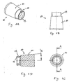
- the Figures 1A to 1D show different views of the fastener 10 of the fastening device according to the invention.
- the fastening element 10 has an axially conical anchoring region 11 and a fastening region 12.
- the opening angle of the conical region is denoted by ⁇ .
- the attachment portion 12 has on its outside a thread on which a cap can be screwed.
- the attachment region has a support section 13, on which a retroreflector ball is placed, for example, by a magnet (not shown) can when the fastener is arranged in a bottom hole.
- This arrangement is such that the end of the larger diameter conical portion in the bottom hole faces downward.
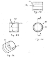
- FIGS. 2A to 2D show different views of the clamping sleeve 20 of the fastening device according to the invention.
- the clamping sleeve 20 is conically formed on its inside, in such a way that the opening angle to that of the conical anchoring portion 11 of the fastener 10 after FIG. 1 equivalent.
- the clamping sleeve 20 has a longitudinal slot 21.
- the outside of the clamping sleeve 20 is also provided with conical barbs 22 which can get caught with unevenness of the building material.
- FIGS. 3A to 3D show various views of the entire fastening device according to the invention 30.
- the entire fastening device 30 consists of the fastening element 10, the clamping sleeve 20 and a cover 31st
- the procedure for anchoring the fastening device is as follows. First, a hole is drilled or broken in the building material, for example in a concrete floor. The diameter of the borehole is only slightly larger than the largest diameter of the conical anchoring region 11 of the fastening element 10. The fastening element 10 is then inserted into the borehole and, e.g. leveled with sand in the height. Subsequently, the clamping sleeve 20 is placed on the conical anchoring region 11 and clamped with a laid on the inner edge 23 Einschlagadapter by a blow in the axial direction between the anchoring region 11 and the building material.
- the clamping sleeve 20 expands due to the slot 21 in the radial direction, so that a frictional connection between the conical anchoring region 11 of the fastener 10 of the clamping sleeve 20 and the building material comes off.
- the anchor is in case of need, at least partially, preferably made entirely of plastic in order as possible both in hard material such as concrete and in softer material such. B. gas or aerated concrete can be used.
- An important object of the invention is to design the dowel so that it is equally suitable for different fields of application, z.
- anchors or as a retractable mount for retroreflectors as used in the optical 3D metrology, for example, as a benchmark in the measurement of particle accelerator.
- the fastener is provided with an external thread as well as with a spherical cap.
- the anchoring of the dowel in the borehole is carried out by the conical sleeve is widened uniformly in the radial direction with a Einschlagadapter by a blow in the axial direction by the conical fastener.
- the sleeve has conical barbs that ensure that extremely high pull-out values are achieved.
- the dowel Since the dowel is suitable for receiving a wide variety of bodies that can change regularly, it must be ensured that the retroreflector receptacle / thread of the fastening element is not damaged. According to the invention, this is realized by a fully retractable, watertight closing cover, which is screwed onto the fastening element.
Landscapes
- Engineering & Computer Science (AREA)
- General Engineering & Computer Science (AREA)
- Mechanical Engineering (AREA)
- Joining Of Building Structures In Genera (AREA)
- Dowels (AREA)
Claims (11)
- Dispositif de fixation (30) destiné à l'ancrage dans un matériau de construction, et comprenant
un élément de fixation (10), qui présente une zone d'ancrage (11) axialement conique et une zone de fixation (12), et
une douille de serrage (20) radialement extensible, qui peut être serrée entre la zone d'ancrage et le matériau de construction ;
un cabochon de recouvrement (31) pour recouvrir l'élément de fixation (10) ;
dispositif de fixation
dans lequel le côté intérieur de la douille de serrage (20) est de configuration conique, avec un angle qui correspond à celui de la zone d'ancrage (11) conique ; et
dans lequel le cabochon de recouvrement (31) peut être vissé sur un filetage de l'élément de fixation (10) de manière telle que le cabochon de recouvrement arrive au ras d'une surface externe du matériau de construction. - Dispositif de fixation selon la revendication 1, dans lequel les dimensionnements de la zone d'ancrage et de la douille de serrage sont mutuellement adaptés l'un à l'autre, de manière à ce que la zone d'ancrage puisse produire, en vue du serrage, une expansion radiale de la douille de serrage.
- Dispositif de fixation selon la revendication 1 ou la revendication 2, dans lequel le côté intérieur de la douille de serrage peut être amené en contact de surface avec le côté extérieur de la zone d'ancrage conique.
- Dispositif de fixation selon l'une des revendications précédentes, dans lequel la douille de serrage présente une fente longitudinale (21).
- Dispositif de fixation selon l'une des revendications précédentes, dans lequel la matière de la douille de serrage comprend une matière plastique, notamment du PVC dur, ou un métal, notamment du laiton.
- Dispositif de fixation selon l'une des revendications précédentes, dans lequel la zone de fixation comprend un filetage, notamment une broche filetée, et/ou une calotte, notamment une calotte sphérique, et/ou un système de crochet et/ou un anneau et/ou un aimant et/ou un système à baïonnette et/ou une surface de collage.
- Dispositif de fixation selon l'une des revendications précédentes, dans lequel l'élément de fixation comprend du métal, de préférence un acier de décolletage.
- Dispositif de fixation selon l'une des revendications précédentes, dans lequel la zone d'ancrage conique se rétrécit en direction de la zone de fixation.
- Dispositif de fixation selon l'une des revendications précédentes, dans lequel la douille de serrage présente sur son côté extérieur, des griffes d'accrochage coniques (22).
- Procédé pour assurer l'ancrage d'un dispositif de fixation selon l'une des revendications précédentes, dans un matériau de construction, le procédé comprenant les étapes suivantes :insertion de l'élément de fixation dans un trou d'ancrage, notamment un perçage, dans le matériau de construction, la zone d'ancrage conique se rétrécissant en direction du côté ouvert du trou d'ancrage,serrage de la douille de serrage entre la zone d'ancrage et le matériau de construction.
- Procédé selon la revendication 10, d'après lequel le serrage de la douille de serrage s'effectue par l'action momentanée d'une force sur la douille de serrage, notamment par frappe dans la direction axiale sur un adaptateur de frappe appliqué sur la douille de serrage, en faisant ainsi glisser la douille de serrage par-dessus la zone d'ancrage axialement conique, qui produit l'expansion radiale de la douille de serrage et le serrage de celle-ci entre la zone d'ancrage et le matériau de construction.
Priority Applications (4)
| Application Number | Priority Date | Filing Date | Title |
|---|---|---|---|
| ES08007880T ES2435439T3 (es) | 2008-04-23 | 2008-04-23 | Clavija con elemento de fijación y manguito |
| EP08007880.1A EP2112384B1 (fr) | 2008-04-23 | 2008-04-23 | Cheville dotée d'un élément de fixation et d'une douille |
| PCT/EP2009/002966 WO2009130027A1 (fr) | 2008-04-23 | 2009-04-23 | Cheville comprenant un élément de fixation et une douille |
| US12/988,782 US8876449B2 (en) | 2008-04-23 | 2009-04-23 | Plug with fixing element and sleeve |
Applications Claiming Priority (1)
| Application Number | Priority Date | Filing Date | Title |
|---|---|---|---|
| EP08007880.1A EP2112384B1 (fr) | 2008-04-23 | 2008-04-23 | Cheville dotée d'un élément de fixation et d'une douille |
Publications (2)
| Publication Number | Publication Date |
|---|---|
| EP2112384A1 EP2112384A1 (fr) | 2009-10-28 |
| EP2112384B1 true EP2112384B1 (fr) | 2013-08-21 |
Family
ID=39745464
Family Applications (1)
| Application Number | Title | Priority Date | Filing Date |
|---|---|---|---|
| EP08007880.1A Not-in-force EP2112384B1 (fr) | 2008-04-23 | 2008-04-23 | Cheville dotée d'un élément de fixation et d'une douille |
Country Status (4)
| Country | Link |
|---|---|
| US (1) | US8876449B2 (fr) |
| EP (1) | EP2112384B1 (fr) |
| ES (1) | ES2435439T3 (fr) |
| WO (1) | WO2009130027A1 (fr) |
Families Citing this family (6)
| Publication number | Priority date | Publication date | Assignee | Title |
|---|---|---|---|---|
| US9909330B2 (en) | 2012-05-22 | 2018-03-06 | Gerald R. Gray | Method and apparatus to fill and fire proof holes in concrete floors |
| US8959863B2 (en) | 2012-05-22 | 2015-02-24 | Gerald R. Gray | Method and apparatus to fill and fire proof holes in concrete floors of commercial buildings utilizing a precast plug |
| US9765541B2 (en) | 2012-05-22 | 2017-09-19 | Gerald R. Gray | Method and apparatus to fill and fire proof holes in concrete floors |
| EP3069153A2 (fr) * | 2013-11-13 | 2016-09-21 | Philips Lighting Holding B.V. | Détection de problèmes dans un système de câbles |
| US9986728B2 (en) * | 2015-10-28 | 2018-06-05 | Lary Adkins | Termiticide flex plug system and method |
| WO2019066753A2 (fr) * | 2017-09-26 | 2019-04-04 | Di̇renç Metal Ve Metal Bağlanti Elem. Tas. Üreti̇m Ve Pazarlama Li̇mi̇ted Şi̇rketi̇ | Patte de fixation pour évier |
Family Cites Families (13)
| Publication number | Priority date | Publication date | Assignee | Title |
|---|---|---|---|---|
| US688756A (en) * | 1900-05-24 | 1901-12-10 | Jacob W Tripp | Expansion-bolt. |
| US688758A (en) * | 1900-07-06 | 1901-12-10 | Robert J Victor | Port-light for marine craft. |
| US777399A (en) * | 1903-04-06 | 1904-12-13 | Isaac Church | Expansion-bolt. |
| CH325754A (de) * | 1954-10-13 | 1957-11-30 | Kurzen Paul | Mauerschraube |
| DK135813C (da) * | 1967-04-05 | 1977-11-21 | Mortensen L | Ekspansionsbolt |
| CH492890A (fr) * | 1968-10-08 | 1970-06-30 | Etem Ets De Tech Mod | Cheville de fixation |
| DE2548495A1 (de) * | 1974-11-01 | 1976-05-06 | Adbar Patent Co Ltd | Einsatz |
| US4371300A (en) * | 1980-01-26 | 1983-02-01 | Adbar (Patent Co.) Limited | Insert |
| NZ223633A (en) * | 1987-02-25 | 1991-11-26 | Prospection & Inventions | Expanding eye-bolt: fastener expanded by withdrawal force on eye |
| US4861198A (en) * | 1988-11-22 | 1989-08-29 | Jennmar Corporation | Expansion assembly for mine roof bolts |
| FR2657402B1 (fr) * | 1990-01-25 | 1992-05-15 | Titeux Sa Ferronnerie | Cheville auto-bloquante de securite. |
| DE10339147A1 (de) * | 2003-08-26 | 2005-03-24 | Brückl-Gesellschaft für Befestigungssysteme mbH | Schwerlastanker |
| DE10353237A1 (de) * | 2003-09-26 | 2005-07-28 | Fischerwerke Artur Fischer Gmbh & Co. Kg | Befestigungselement, Anordnung und Verfahren zur Verankerung in einem kurzen, nicht hinterschnittenen Sackloch |
-
2008
- 2008-04-23 EP EP08007880.1A patent/EP2112384B1/fr not_active Not-in-force
- 2008-04-23 ES ES08007880T patent/ES2435439T3/es active Active
-
2009
- 2009-04-23 WO PCT/EP2009/002966 patent/WO2009130027A1/fr not_active Ceased
- 2009-04-23 US US12/988,782 patent/US8876449B2/en active Active
Also Published As
| Publication number | Publication date |
|---|---|
| US8876449B2 (en) | 2014-11-04 |
| US20110110743A1 (en) | 2011-05-12 |
| ES2435439T3 (es) | 2013-12-19 |
| EP2112384A1 (fr) | 2009-10-28 |
| WO2009130027A1 (fr) | 2009-10-29 |
Similar Documents
| Publication | Publication Date | Title |
|---|---|---|
| EP2309138B1 (fr) | Piton à expansion | |
| WO2009130027A1 (fr) | Cheville comprenant un élément de fixation et une douille | |
| DE60300630T2 (de) | Tief einführbarer und entfernbarer Anker | |
| EP2992226B1 (fr) | Système d'ancrage | |
| EP2354567B1 (fr) | Vis de tige d'encrage | |
| EP3507509A1 (fr) | Capteur de distance sur la pointe de l'ancre | |
| EP2171293B1 (fr) | Element d'ancrage a expansion et procede d'ancrage de cet element dans une base d'ancrage de preference a proximite de la surface | |
| EP2003270A2 (fr) | Système et procédé de fixation d'un objet en forme de mât ou de poteau dans le sol en terre avec une partie réceptrice en plusieurs pièces pouvant être vissées sur le sol en terre | |
| DE202010012930U1 (de) | Bauwerkanker | |
| EP1518056B1 (fr) | Piton a expansion en matiere plastique | |
| DE2412901A1 (de) | Spreizduebel | |
| DE2552435A1 (de) | Mauerspreizduebel mit durchlaufsperre fuer einlagen | |
| EP0056255A1 (fr) | Dispositif pour l'attachement d'objets à un mur en béton | |
| EP0635645B1 (fr) | Douille | |
| DE4215435C2 (de) | Schalldämmende Verbindung | |
| EP1970575A2 (fr) | Piton à expansion pour mur à double paroi | |
| DE102008053638A1 (de) | Vorrichtung zum Justieren eines Bauelementes in einem Abstand zum Bauteil | |
| EP0997650A1 (fr) | Cheville d'expansion | |
| DE20218372U1 (de) | Zentrierhilfe zur Injektionsbefestigung | |
| WO2005108803A1 (fr) | Cheville | |
| EP3084234B1 (fr) | Dispositif de cheville de déport | |
| EP2063135B1 (fr) | Cheville à expansion | |
| EP0913592A1 (fr) | Cheville à percussion | |
| DE1911632A1 (de) | Bolzenfoermiges Befestigungselement | |
| DE3631544A1 (de) | Verfahren zum verankern von bauteilen in insbesondere beton |
Legal Events
| Date | Code | Title | Description |
|---|---|---|---|
| PUAI | Public reference made under article 153(3) epc to a published international application that has entered the european phase |
Free format text: ORIGINAL CODE: 0009012 |
|
| AK | Designated contracting states |
Kind code of ref document: A1 Designated state(s): AT BE BG CH CY CZ DE DK EE ES FI FR GB GR HR HU IE IS IT LI LT LU LV MC MT NL NO PL PT RO SE SI SK TR |
|
| AX | Request for extension of the european patent |
Extension state: AL BA MK RS |
|
| 17P | Request for examination filed |
Effective date: 20100428 |
|
| AKX | Designation fees paid |
Designated state(s): AT BE BG CH CY CZ DE DK EE ES FI FR GB GR HR HU IE IS IT LI LT LU LV MC MT NL NO PL PT RO SE SI SK TR |
|
| 17Q | First examination report despatched |
Effective date: 20100615 |
|
| GRAP | Despatch of communication of intention to grant a patent |
Free format text: ORIGINAL CODE: EPIDOSNIGR1 |
|
| GRAS | Grant fee paid |
Free format text: ORIGINAL CODE: EPIDOSNIGR3 |
|
| GRAA | (expected) grant |
Free format text: ORIGINAL CODE: 0009210 |
|
| AK | Designated contracting states |
Kind code of ref document: B1 Designated state(s): AT BE BG CH CY CZ DE DK EE ES FI FR GB GR HR HU IE IS IT LI LT LU LV MC MT NL NO PL PT RO SE SI SK TR |
|
| REG | Reference to a national code |
Ref country code: GB Ref legal event code: FG4D Free format text: NOT ENGLISH |
|
| REG | Reference to a national code |
Ref country code: CH Ref legal event code: EP |
|
| REG | Reference to a national code |
Ref country code: CH Ref legal event code: NV Representative=s name: BOHEST AG, CH |
|
| REG | Reference to a national code |
Ref country code: AT Ref legal event code: REF Ref document number: 628276 Country of ref document: AT Kind code of ref document: T Effective date: 20130915 |
|
| REG | Reference to a national code |
Ref country code: IE Ref legal event code: FG4D Free format text: LANGUAGE OF EP DOCUMENT: GERMAN |
|
| REG | Reference to a national code |
Ref country code: DE Ref legal event code: R096 Ref document number: 502008010511 Country of ref document: DE Effective date: 20131017 |
|
| REG | Reference to a national code |
Ref country code: NL Ref legal event code: T3 |
|
| REG | Reference to a national code |
Ref country code: ES Ref legal event code: FG2A Ref document number: 2435439 Country of ref document: ES Kind code of ref document: T3 Effective date: 20131219 |
|
| REG | Reference to a national code |
Ref country code: LT Ref legal event code: MG4D |
|
| PG25 | Lapsed in a contracting state [announced via postgrant information from national office to epo] |
Ref country code: HR Free format text: LAPSE BECAUSE OF FAILURE TO SUBMIT A TRANSLATION OF THE DESCRIPTION OR TO PAY THE FEE WITHIN THE PRESCRIBED TIME-LIMIT Effective date: 20130821 Ref country code: LT Free format text: LAPSE BECAUSE OF FAILURE TO SUBMIT A TRANSLATION OF THE DESCRIPTION OR TO PAY THE FEE WITHIN THE PRESCRIBED TIME-LIMIT Effective date: 20130821 Ref country code: CY Free format text: LAPSE BECAUSE OF FAILURE TO SUBMIT A TRANSLATION OF THE DESCRIPTION OR TO PAY THE FEE WITHIN THE PRESCRIBED TIME-LIMIT Effective date: 20130807 Ref country code: PT Free format text: LAPSE BECAUSE OF FAILURE TO SUBMIT A TRANSLATION OF THE DESCRIPTION OR TO PAY THE FEE WITHIN THE PRESCRIBED TIME-LIMIT Effective date: 20131223 Ref country code: SE Free format text: LAPSE BECAUSE OF FAILURE TO SUBMIT A TRANSLATION OF THE DESCRIPTION OR TO PAY THE FEE WITHIN THE PRESCRIBED TIME-LIMIT Effective date: 20130821 Ref country code: IS Free format text: LAPSE BECAUSE OF FAILURE TO SUBMIT A TRANSLATION OF THE DESCRIPTION OR TO PAY THE FEE WITHIN THE PRESCRIBED TIME-LIMIT Effective date: 20131221 Ref country code: NO Free format text: LAPSE BECAUSE OF FAILURE TO SUBMIT A TRANSLATION OF THE DESCRIPTION OR TO PAY THE FEE WITHIN THE PRESCRIBED TIME-LIMIT Effective date: 20131121 |
|
| PG25 | Lapsed in a contracting state [announced via postgrant information from national office to epo] |
Ref country code: PL Free format text: LAPSE BECAUSE OF FAILURE TO SUBMIT A TRANSLATION OF THE DESCRIPTION OR TO PAY THE FEE WITHIN THE PRESCRIBED TIME-LIMIT Effective date: 20130821 Ref country code: GR Free format text: LAPSE BECAUSE OF FAILURE TO SUBMIT A TRANSLATION OF THE DESCRIPTION OR TO PAY THE FEE WITHIN THE PRESCRIBED TIME-LIMIT Effective date: 20131122 Ref country code: SI Free format text: LAPSE BECAUSE OF FAILURE TO SUBMIT A TRANSLATION OF THE DESCRIPTION OR TO PAY THE FEE WITHIN THE PRESCRIBED TIME-LIMIT Effective date: 20130821 Ref country code: FI Free format text: LAPSE BECAUSE OF FAILURE TO SUBMIT A TRANSLATION OF THE DESCRIPTION OR TO PAY THE FEE WITHIN THE PRESCRIBED TIME-LIMIT Effective date: 20130821 Ref country code: LV Free format text: LAPSE BECAUSE OF FAILURE TO SUBMIT A TRANSLATION OF THE DESCRIPTION OR TO PAY THE FEE WITHIN THE PRESCRIBED TIME-LIMIT Effective date: 20130821 |
|
| PG25 | Lapsed in a contracting state [announced via postgrant information from national office to epo] |
Ref country code: CY Free format text: LAPSE BECAUSE OF FAILURE TO SUBMIT A TRANSLATION OF THE DESCRIPTION OR TO PAY THE FEE WITHIN THE PRESCRIBED TIME-LIMIT Effective date: 20130821 |
|
| PG25 | Lapsed in a contracting state [announced via postgrant information from national office to epo] |
Ref country code: SK Free format text: LAPSE BECAUSE OF FAILURE TO SUBMIT A TRANSLATION OF THE DESCRIPTION OR TO PAY THE FEE WITHIN THE PRESCRIBED TIME-LIMIT Effective date: 20130821 Ref country code: DK Free format text: LAPSE BECAUSE OF FAILURE TO SUBMIT A TRANSLATION OF THE DESCRIPTION OR TO PAY THE FEE WITHIN THE PRESCRIBED TIME-LIMIT Effective date: 20130821 Ref country code: RO Free format text: LAPSE BECAUSE OF FAILURE TO SUBMIT A TRANSLATION OF THE DESCRIPTION OR TO PAY THE FEE WITHIN THE PRESCRIBED TIME-LIMIT Effective date: 20130821 Ref country code: EE Free format text: LAPSE BECAUSE OF FAILURE TO SUBMIT A TRANSLATION OF THE DESCRIPTION OR TO PAY THE FEE WITHIN THE PRESCRIBED TIME-LIMIT Effective date: 20130821 Ref country code: CZ Free format text: LAPSE BECAUSE OF FAILURE TO SUBMIT A TRANSLATION OF THE DESCRIPTION OR TO PAY THE FEE WITHIN THE PRESCRIBED TIME-LIMIT Effective date: 20130821 |
|
| PLBE | No opposition filed within time limit |
Free format text: ORIGINAL CODE: 0009261 |
|
| STAA | Information on the status of an ep patent application or granted ep patent |
Free format text: STATUS: NO OPPOSITION FILED WITHIN TIME LIMIT |
|
| 26N | No opposition filed |
Effective date: 20140522 |
|
| PGFP | Annual fee paid to national office [announced via postgrant information from national office to epo] |
Ref country code: GB Payment date: 20140423 Year of fee payment: 7 |
|
| REG | Reference to a national code |
Ref country code: CH Ref legal event code: PCAR Free format text: NEW ADDRESS: HOLBEINSTRASSE 36-38, 4051 BASEL (CH) |
|
| PGFP | Annual fee paid to national office [announced via postgrant information from national office to epo] |
Ref country code: IT Payment date: 20140423 Year of fee payment: 7 Ref country code: FR Payment date: 20140416 Year of fee payment: 7 Ref country code: CH Payment date: 20140422 Year of fee payment: 7 Ref country code: NL Payment date: 20140417 Year of fee payment: 7 Ref country code: AT Payment date: 20140417 Year of fee payment: 7 Ref country code: ES Payment date: 20140417 Year of fee payment: 7 |
|
| REG | Reference to a national code |
Ref country code: DE Ref legal event code: R097 Ref document number: 502008010511 Country of ref document: DE Effective date: 20140522 |
|
| REG | Reference to a national code |
Ref country code: CH Ref legal event code: PUE Owner name: BRUNSON INSTRUMENT COMPANY, US Free format text: FORMER OWNER: AFM TECHNOLOGY GMBH, DE |
|
| PG25 | Lapsed in a contracting state [announced via postgrant information from national office to epo] |
Ref country code: MC Free format text: LAPSE BECAUSE OF FAILURE TO SUBMIT A TRANSLATION OF THE DESCRIPTION OR TO PAY THE FEE WITHIN THE PRESCRIBED TIME-LIMIT Effective date: 20130821 Ref country code: LU Free format text: LAPSE BECAUSE OF FAILURE TO SUBMIT A TRANSLATION OF THE DESCRIPTION OR TO PAY THE FEE WITHIN THE PRESCRIBED TIME-LIMIT Effective date: 20140423 |
|
| REG | Reference to a national code |
Ref country code: DE Ref legal event code: R082 Ref document number: 502008010511 Country of ref document: DE Representative=s name: MITSCHERLICH, PATENT- UND RECHTSANWAELTE PARTM, DE |
|
| REG | Reference to a national code |
Ref country code: IE Ref legal event code: MM4A |
|
| REG | Reference to a national code |
Ref country code: DE Ref legal event code: R081 Ref document number: 502008010511 Country of ref document: DE Owner name: BRUNSON INSTRUMENT COMPANY, KANSAS CITY, US Free format text: FORMER OWNER: AFM TECHNOLOGY GMBH, 73430 AALEN, DE Effective date: 20141223 Ref country code: DE Ref legal event code: R082 Ref document number: 502008010511 Country of ref document: DE Representative=s name: MITSCHERLICH, PATENT- UND RECHTSANWAELTE PARTM, DE Effective date: 20141223 Ref country code: DE Ref legal event code: R082 Ref document number: 502008010511 Country of ref document: DE Representative=s name: HASELTINE LAKE LLP, DE Effective date: 20141223 |
|
| REG | Reference to a national code |
Ref country code: DE Ref legal event code: R082 Ref document number: 502008010511 Country of ref document: DE Representative=s name: HASELTINE LAKE LLP, DE |
|
| PG25 | Lapsed in a contracting state [announced via postgrant information from national office to epo] |
Ref country code: IE Free format text: LAPSE BECAUSE OF NON-PAYMENT OF DUE FEES Effective date: 20140423 |
|
| REG | Reference to a national code |
Ref country code: CH Ref legal event code: PL |
|
| REG | Reference to a national code |
Ref country code: AT Ref legal event code: MM01 Ref document number: 628276 Country of ref document: AT Kind code of ref document: T Effective date: 20150423 |
|
| GBPC | Gb: european patent ceased through non-payment of renewal fee |
Effective date: 20150423 |
|
| REG | Reference to a national code |
Ref country code: NL Ref legal event code: MM Effective date: 20150501 |
|
| PG25 | Lapsed in a contracting state [announced via postgrant information from national office to epo] |
Ref country code: LI Free format text: LAPSE BECAUSE OF NON-PAYMENT OF DUE FEES Effective date: 20150430 Ref country code: CH Free format text: LAPSE BECAUSE OF NON-PAYMENT OF DUE FEES Effective date: 20150430 Ref country code: GB Free format text: LAPSE BECAUSE OF NON-PAYMENT OF DUE FEES Effective date: 20150423 Ref country code: IT Free format text: LAPSE BECAUSE OF NON-PAYMENT OF DUE FEES Effective date: 20150423 |
|
| REG | Reference to a national code |
Ref country code: FR Ref legal event code: ST Effective date: 20151231 |
|
| PG25 | Lapsed in a contracting state [announced via postgrant information from national office to epo] |
Ref country code: FR Free format text: LAPSE BECAUSE OF NON-PAYMENT OF DUE FEES Effective date: 20150430 Ref country code: AT Free format text: LAPSE BECAUSE OF NON-PAYMENT OF DUE FEES Effective date: 20150423 |
|
| PG25 | Lapsed in a contracting state [announced via postgrant information from national office to epo] |
Ref country code: MT Free format text: LAPSE BECAUSE OF FAILURE TO SUBMIT A TRANSLATION OF THE DESCRIPTION OR TO PAY THE FEE WITHIN THE PRESCRIBED TIME-LIMIT Effective date: 20130821 Ref country code: NL Free format text: LAPSE BECAUSE OF NON-PAYMENT OF DUE FEES Effective date: 20150501 |
|
| REG | Reference to a national code |
Ref country code: ES Ref legal event code: FD2A Effective date: 20160526 |
|
| PG25 | Lapsed in a contracting state [announced via postgrant information from national office to epo] |
Ref country code: BG Free format text: LAPSE BECAUSE OF FAILURE TO SUBMIT A TRANSLATION OF THE DESCRIPTION OR TO PAY THE FEE WITHIN THE PRESCRIBED TIME-LIMIT Effective date: 20130821 |
|
| PG25 | Lapsed in a contracting state [announced via postgrant information from national office to epo] |
Ref country code: TR Free format text: LAPSE BECAUSE OF FAILURE TO SUBMIT A TRANSLATION OF THE DESCRIPTION OR TO PAY THE FEE WITHIN THE PRESCRIBED TIME-LIMIT Effective date: 20130821 Ref country code: HU Free format text: LAPSE BECAUSE OF FAILURE TO SUBMIT A TRANSLATION OF THE DESCRIPTION OR TO PAY THE FEE WITHIN THE PRESCRIBED TIME-LIMIT; INVALID AB INITIO Effective date: 20080423 Ref country code: ES Free format text: LAPSE BECAUSE OF NON-PAYMENT OF DUE FEES Effective date: 20150424 Ref country code: BE Free format text: LAPSE BECAUSE OF FAILURE TO SUBMIT A TRANSLATION OF THE DESCRIPTION OR TO PAY THE FEE WITHIN THE PRESCRIBED TIME-LIMIT Effective date: 20140430 |
|
| REG | Reference to a national code |
Ref country code: DE Ref legal event code: R082 Ref document number: 502008010511 Country of ref document: DE Representative=s name: HL KEMPNER PATENTANWAELTE, SOLICITORS (ENGLAND, DE Ref country code: DE Ref legal event code: R082 Ref document number: 502008010511 Country of ref document: DE Representative=s name: HL KEMPNER PATENTANWALT, RECHTSANWALT, SOLICIT, DE Ref country code: DE Ref legal event code: R082 Ref document number: 502008010511 Country of ref document: DE Representative=s name: HL KEMPNER PARTG MBB, DE |
|
| PGFP | Annual fee paid to national office [announced via postgrant information from national office to epo] |
Ref country code: DE Payment date: 20240416 Year of fee payment: 17 |
|
| REG | Reference to a national code |
Ref country code: DE Ref legal event code: R119 Ref document number: 502008010511 Country of ref document: DE |
|
| PG25 | Lapsed in a contracting state [announced via postgrant information from national office to epo] |
Ref country code: DE Free format text: LAPSE BECAUSE OF NON-PAYMENT OF DUE FEES Effective date: 20251104 |