EP2112475A1 - Agencement de capteurs - Google Patents
Agencement de capteurs Download PDFInfo
- Publication number
- EP2112475A1 EP2112475A1 EP08154879A EP08154879A EP2112475A1 EP 2112475 A1 EP2112475 A1 EP 2112475A1 EP 08154879 A EP08154879 A EP 08154879A EP 08154879 A EP08154879 A EP 08154879A EP 2112475 A1 EP2112475 A1 EP 2112475A1
- Authority
- EP
- European Patent Office
- Prior art keywords
- sensor
- sensor element
- magnetic
- sensor arrangement
- arrangement according
- Prior art date
- Legal status (The legal status is an assumption and is not a legal conclusion. Google has not performed a legal analysis and makes no representation as to the accuracy of the status listed.)
- Granted
Links
- 230000005291 magnetic effect Effects 0.000 claims abstract description 56
- 239000012530 fluid Substances 0.000 claims abstract description 37
- 230000004907 flux Effects 0.000 claims abstract description 10
- 239000004020 conductor Substances 0.000 claims description 11
- 230000002093 peripheral effect Effects 0.000 claims description 8
- 239000000696 magnetic material Substances 0.000 claims description 7
- 239000000463 material Substances 0.000 description 3
- 238000003754 machining Methods 0.000 description 2
- 238000000034 method Methods 0.000 description 2
- 229910000831 Steel Inorganic materials 0.000 description 1
- 239000011248 coating agent Substances 0.000 description 1
- 238000000576 coating method Methods 0.000 description 1
- 238000001514 detection method Methods 0.000 description 1
- 230000005294 ferromagnetic effect Effects 0.000 description 1
- 230000002452 interceptive effect Effects 0.000 description 1
- 230000007257 malfunction Effects 0.000 description 1
- 238000004519 manufacturing process Methods 0.000 description 1
- 239000007769 metal material Substances 0.000 description 1
- 239000010959 steel Substances 0.000 description 1
Images

Classifications
-
- G—PHYSICS
- G01—MEASURING; TESTING
- G01D—MEASURING NOT SPECIALLY ADAPTED FOR A SPECIFIC VARIABLE; ARRANGEMENTS FOR MEASURING TWO OR MORE VARIABLES NOT COVERED IN A SINGLE OTHER SUBCLASS; TARIFF METERING APPARATUS; MEASURING OR TESTING NOT OTHERWISE PROVIDED FOR
- G01D5/00—Mechanical means for transferring the output of a sensing member; Means for converting the output of a sensing member to another variable where the form or nature of the sensing member does not constrain the means for converting; Transducers not specially adapted for a specific variable
- G01D5/12—Mechanical means for transferring the output of a sensing member; Means for converting the output of a sensing member to another variable where the form or nature of the sensing member does not constrain the means for converting; Transducers not specially adapted for a specific variable using electric or magnetic means
- G01D5/14—Mechanical means for transferring the output of a sensing member; Means for converting the output of a sensing member to another variable where the form or nature of the sensing member does not constrain the means for converting; Transducers not specially adapted for a specific variable using electric or magnetic means influencing the magnitude of a current or voltage
Definitions
- the present invention relates generally to a sensor arrangement for detecting at least one position of a displaceable component in a fluid device.
- a conventional sensor used for this purpose is a magnetic sensor, commonly referred to as a Hall sensor.
- US 6 283 149 discloses a sensor arrangement for a directional control valve, where a magnetic sensor is mounted in a blind bore in the valve body. Magnets are provided in an outer radial surface of the spool, which magnets are used by the sensor for determining the position of the spool. This arrangement requires the sensor to detect a magnet through a section of the wall, which may reduce the accuracy of the sensor. The solution also requires additional machining of both the valve body, to allow mounting of the sensor, and the spool, to allow magnets to be mounted on the spool. This makes the manufacture of the valve unnecessarily complex and expensive.
- WO 2007/076750 discloses an alternative arrangement for mounting a sensor.
- the sensor is mounted in a bore exiting in a cavity for a spool in a valve body.
- the sensor uses magnets mounted on a projection on the spool to detect the position thereof.
- This arrangement exposes the sensor to the hydraulic fluid in the cavity, which may cause the sensor to corrode and eventually malfunction.
- This solution also requires additional machining of the spool, to allow magnets to be mounted on the spool.
- One object of the present invention is to provide an improved arrangement for detecting the position of a displaceable component in a fluid device, which arrangement solves the problems stated above.
- the invention aims to provide a sensor arrangement having an improved accuracy and which is less affected by hydraulic fluid.
- the invention relates to a sensor arrangement arranged to detect at least one position of a displaceable component in a fluid device.
- the fluid device may be a spool valve, a directional control valve, a piston-cylinder device, or similar.
- the fluid device comprises a wall enclosing a cavity, in which cavity the said component is displaced by a fluid selectively applied to the component.
- the device may be operated using a suitable hydraulic, pneumatic or similar source of fluid pressure supplied from a pump, compressor, accumulator or a similar device.
- the sensor arrangement preferably comprises a magnetic sensor, such as a Hall sensor, mounted outside the wall, and cooperating first and second sensor elements.
- the first sensor element is connected to the magnetic sensor and extends through said wall and a predetermined distance into the cavity, wherein the magnetic sensor is arranged to detect the position of at least one predetermined second sensor element located on the displaceable component by sensing a change in magnetic flux induced in the first sensor element by the second sensor element.
- the distance between the first and second elements can be reduced in order to improve the accuracy of the sensor.
- the change in the magnetic field in the first sensor element is proportional to the distance between the second sensor element and first sensor element. This will in turn allow position sensing using surfaces that are remote from any wear surfaces and which may not be available or suitable for this purpose using known sensor arrangements.
- the first sensor element that is connected to the sensor is a magnetically conductive material, such as a suitable ferromagnetic metallic material.
- the second sensor element mounted on the displaceable component is a magnet, such as a permanent magnet.
- the first sensor element is a magnet
- the second sensor element is a magnetically conductive material
- the magnetic sensor may be a magnetically sensing element is formed by a Hall sensor or a pickup coil mounted on or adjacent an outer surface of the wall. In this way the sensor is neither exposed to the fluid in the cavity of the fluid device, nor to high pressures that may occur therein.
- the magnetic sensor is connected to an electronic control unit or a signal detecting unit, which receives electrical pulses representing the change in magnetic flux induced in the first sensor element by the second sensor element. Based on these input signals and information relating to the fluid operation and current direction of movement of the displaceable component, the electronic control unit can determine the position of said component.
- the magnetic sensor may be attached on and connected to the first sensor element.
- the first sensor element may be mounted in a plug that encases the longitudinal surfaces of the element extending through the wall and into the cavity.
- the first sensor element is separated from the wall by an isolating non-magnetic material. This may be achieved by providing the first sensor element with a coating of a suitable non-magnetic material or by mounting the first sensor element in a non-magnetic casing. In the latter case, the casing surrounding the first sensor element can be made from an insulating non-magnetic material.
- the first sensor element can be a cylindrical body, but other cross-sections are also possible.
- the displaceable component may be displaceable along a longitudinal axis and the second sensor element is an end surface of the displaceable component.
- This arrangement is mainly suited for detecting an end position of the displaceable component as it is displaced in the cavity.
- the displaceable component is arranged to be displaceable along a longitudinal axis and the second sensor element comprises at least one peripheral element on the displaceable component.
- This arrangement is mainly suited for detecting one or more individual positions or for continuous detection of the position of the displaceable component as it is displaced in the cavity.
- the magnetic sensor may be arranged to detect the position of each of a single second sensor element or a number of consecutive and separated peripheral second sensor elements along the longitudinal axis.
- the second sensor element comprises one or more magnets
- the said magnet or magnets may be located in a peripheral surface of the displaceable component, or in a holder attached to an end thereof.
- the second sensor element comprises a magnetically conductive material
- the consecutive elements may comprise a number of material sections of a predetermined shape arranged at the same distance from the longitudinal axis and a predetermined axial thickness, or a row of individual teeth with a predetermined spacing.
- the consecutive elements may comprise a number of discs having the same diameter and equal thickness.
- the consecutive elements may be arranged at different distances from the longitudinal axis.
- the consecutive elements may comprise a number of stepped cylindrical surfaces having successively reduced diameters, each with an equal axial extension.
- the invention also relates to a fluid device comprising a sensor arrangement as described above.
- the fluid device may be a spool valve, wherein the position of the spool is detected by the sensor arrangement.
- the fluid device may be a fluid cylinder-piston device, wherein the position of the piston is detected by the sensor arrangement.
- the invention also relates to a vehicle comprising an engine arrangement as described in the above examples.
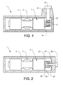
- Figure 1 shows a schematic illustration of a sensor arrangement according to a first embodiment of the invention.
- Figure 1 shows a fluid device in the form of a directional control valve 1.
- the directional control valve 1 comprises a wall 2 enclosing a cavity 3, which cavity contains a displaceable component in the form of a spool 4 that is displaced in the longitudinal cavity 3 along a longitudinal axis of said cavity by pressurized fluid selectively applied to the control valve 1.
- the device may be operated using a suitable hydraulic, pneumatic or similar source of fluid pressure supplied from a pump, compressor, accumulator or a similar device.
- the device is provided with a sensor arrangement comprising a magnetic sensor 10, such as a Hall sensor, mounted outside the wall 2 and a first sensor element 11 that is connected to the magnetic sensor 10 and extends through said wall 2 and a predetermined distance into the cavity 3.
- the magnetic sensor 10 is arranged to detect the position of a second sensor element 12 located on the spool 4 by sensing a change in magnetic flux induced in the first sensor 11 element by the second sensor element 12.
- the first sensor element 11 comprises a cylindrical body of a magnetically conductive material that extends through the wall 2 and in a substantially radial direction into the cavity 3.
- the end surface 13 of the first sensor element 11 may extend as close to the outer surface of the second sensor element 12 as possible without interfering with the function thereof.
- the second sensor element 12 comprises a permanent magnet arranged in the outer peripheral surface of and axially extending end portion 14 of the spool 4.
- the second sensor element 12 is arranged around the entire periphery of the end portion 14 in order to allow position sensing to be performed even if the spool should be rotated about its axis.
- the second sensor element 12 need only be arranged along the section of end portion 14 facing the end surface 13 of the first sensor element 11.
- the wall 2 comprises a material that is not magnetically conductive. If the wall 2 of the directional valve 1 comprises a magnetically conductive material, the first sensor element 11 would have to be insulated from the wall by a suitable non-magnetic material.
- a suitable arrangement for this purpose is described in connection with Figure 3 below.
- FIG. 2 shows a schematic illustration of a sensor arrangement according to a second embodiment of the invention.
- the directional control valve 1 comprises a wall 2 enclosing a cavity 3, which cavity contains a spool 4 displaceable by pressurized fluid selectively applied to the control valve 1.
- the device is provided with a sensor arrangement comprising a magnetic sensor 20, such as a Hall sensor, mounted outside the wall 2, a first sensor element 21 that is connected to the magnetic sensor 20 and extends through said wall 2 and a predetermined distance in a substantially axial direction into the cavity 3.
- the magnetic sensor 20 is arranged to detect the position of a second sensor element 22 located on the spool 4 by sensing a change in magnetic flux induced in the first sensor 21 element by the second sensor element 22.
- the first sensor element 21 comprises a cylindrical body of a magnetically conductive material that extends substantially axially into the cavity 3.
- An end portion 23 of the first sensor element 21 extends into a recess 25 in an axially extending end portion 24 of the spool 4.
- the second sensor element 22 comprises a permanent magnet arranged in the outer peripheral surface of and axially extending end portion 24 of the spool 4.
- the second sensor element 22 is shown arranged around the entire periphery of the end portion 24. However, it is also possible to arrange the second sensor element along an axially extending recess in the outer surface of the end portion 24.
- Figure 3 shows an enlarged view of a first alternative sensor arrangement similar to that of Figure 1 .
- the sensor arrangement comprises a magnetic sensor 30 mounted outside the wall 2 and a first sensor element 31 that is connected to the magnetic sensor 30 and extends through said wall 2 and a predetermined distance into the cavity 3.
- the magnetic sensor 30 is arranged to detect the position of a second sensor element 32 located on an axially extending portion 34 of a spool 4 by sensing a change in magnetic flux induced in the first sensor 31 element by the second sensor element 32.
- the wall 2 of the directional valve 1 comprises a magnetically conductive material.
- said first sensor element 31 is insulated from the wall by a casing 35 made from a suitable non-magnetic material.
- the casing 35, the first sensor element 31 and the magnetic sensor 30 can be made as a unit that is screwed into place in the wall 2 and connected to an electronic control unit (not shown).
- the outer end of the casing can be given a shape that allows it to be mounted with a standard tool and be provided with a flange having a contact surface that ensures that the first sensor element 31 is in position when the contact surface contacts the outer surface of the wall 2.
- the second sensor element 32 can comprise more than one permanent magnet 32a, 32b.
- the magnetic sensor 30 is connected to an electronic control unit (not shown), which receives electrical pulses representing the change in magnetic flux induced in the first sensor element 31 by the magnets 32a, 32b making up the second sensor element 32. Based on these input signals and information relating to the fluid operation and current direction of movement of a spool 4, or a similar displaceable component, the electronic control unit can determine the position of said spool 4.
- Figure 4 shows an enlarged view of a second alternative sensor arrangement.
- the sensor arrangement comprises a magnetic sensor 40 mounted outside the wall 2 and a second sensor element 42 that is connected to the magnetic sensor 40 and extends through said wall 2 and a predetermined distance into the cavity 3.
- the second sensor element 42 comprises a magnet located in a fixed position in the wall 2.
- the magnetic sensor 40 is arranged to detect the position of at least one first sensor element 41 located on an axially extending portion 44 of a spool 4 by sensing a change in magnetic flux induced in the magnetic second sensor element 42 element by at least one first sensor element 41.
- the wall 2 of the directional valve 1 comprises a magnetically conductive material.
- said second sensor element 42 is mounted in a casing 45 made from a suitable non-magnetic material.
- the casing 45, the second sensor element 42 and the magnetic sensor 40 can be made as a unit that is screwed into place in the wall 2 and connected to an electronic control unit (not shown).
- the outer end of the casing can be given a shape that allows it to be mounted with a standard tool and be provided with a flange having a contact surface that ensures that the second sensor element 42 is in position when the contact surface contacts the outer surface of the wall 2.
- the first sensor element 41 can comprise a number of axially separated element s 41 a, 41 b, 41 c.
- the magnetic sensor 40 is connected to an electronic control unit (not shown), which receives electrical pulses representing the change in magnetic flux induced in the magnetic second sensor element 42 by the elements 41 a, 41 b, 41 c making up the first sensor element 41. Based on these input signals and information relating to the fluid operation and current direction of movement of a spool 4, or a similar displaceable component, the electronic control unit can determine the position of said spool 4.
- the magnetic sensor 40 may be achieved by arranging the magnetic sensor 40 to detect the position and direction of movement of each of the consecutive and separated peripheral first sensor elements 41 a, 41 b, 41 c arranged along the longitudinal axis of the spool 4 as they move past the magnetic second sensor element 42.
- the second sensor element 42 comprises a single magnetic body, while the consecutive first sensor elements 41 a, 41 b, 41 c comprise a number of material sections of a predetermined shape arranged at the same distance from the longitudinal axis and a predetermined axial thickness. According to the example shown in Figure 4 , the consecutive elements comprise a number of discs having the same diameter and equal thickness.
- the consecutive elements of Figure 4 may be arranged at different distances from the longitudinal axis.
- the consecutive elements may comprise a number of stepped cylindrical surfaces having successively reduced diameters, each with an equal axial extension.
Landscapes
- Physics & Mathematics (AREA)
- General Physics & Mathematics (AREA)
- Measurement Of Length, Angles, Or The Like Using Electric Or Magnetic Means (AREA)
- Actuator (AREA)
Priority Applications (2)
| Application Number | Priority Date | Filing Date | Title |
|---|---|---|---|
| EP08154879A EP2112475B1 (fr) | 2008-04-21 | 2008-04-21 | Agencement de capteurs |
| US12/420,893 US7788983B2 (en) | 2008-04-21 | 2009-04-09 | Sensor arrangement |
Applications Claiming Priority (1)
| Application Number | Priority Date | Filing Date | Title |
|---|---|---|---|
| EP08154879A EP2112475B1 (fr) | 2008-04-21 | 2008-04-21 | Agencement de capteurs |
Publications (2)
| Publication Number | Publication Date |
|---|---|
| EP2112475A1 true EP2112475A1 (fr) | 2009-10-28 |
| EP2112475B1 EP2112475B1 (fr) | 2012-06-27 |
Family
ID=39708663
Family Applications (1)
| Application Number | Title | Priority Date | Filing Date |
|---|---|---|---|
| EP08154879A Expired - Fee Related EP2112475B1 (fr) | 2008-04-21 | 2008-04-21 | Agencement de capteurs |
Country Status (2)
| Country | Link |
|---|---|
| US (1) | US7788983B2 (fr) |
| EP (1) | EP2112475B1 (fr) |
Cited By (1)
| Publication number | Priority date | Publication date | Assignee | Title |
|---|---|---|---|---|
| EP2431307A3 (fr) * | 2010-09-16 | 2012-04-04 | Montech AG | Transporteur à courroie à vide et soupape de régulation de vide dudit transporteur |
Families Citing this family (10)
| Publication number | Priority date | Publication date | Assignee | Title |
|---|---|---|---|---|
| DE112006003201A5 (de) * | 2005-12-17 | 2008-09-04 | Luk Lamellen Und Kupplungsbau Beteiligungs Kg | Verfahren zur Montage einer Ventileinrichtung und Ventileinrichtung |
| US8485497B2 (en) | 2011-02-08 | 2013-07-16 | Walvoil Fluid Power Usa | Hydraulic valve device with associated spool displacement transducer |
| EP2484949B1 (fr) | 2011-02-08 | 2013-08-28 | Walvoil S.p.A. | Dispositif de vanne hydraulique doté d'un transducteur de déplacement de bobine associé |
| US9657863B2 (en) | 2012-08-30 | 2017-05-23 | Schlumberger Technology Corporation | Sample valve systems and methods |
| MX367380B (es) * | 2013-07-09 | 2019-08-19 | Schlumberger Technology Bv | Sistemas y metodos de deteccion de cambio de valvula. |
| JP6228003B2 (ja) * | 2013-12-26 | 2017-11-08 | サンデンホールディングス株式会社 | 流量検出装置及び可変容量圧縮機 |
| CN104848903A (zh) * | 2014-02-18 | 2015-08-19 | 伊利诺斯工具制品有限公司 | 水流量传感部件、水流量传感器和安装有水流量传感器的热水器 |
| EP2944850B1 (fr) * | 2014-05-12 | 2017-07-12 | HAWE Hydraulik SE | Capteur de position résistant à la pression |
| JP7566607B2 (ja) * | 2020-12-10 | 2024-10-15 | 住友重機械工業株式会社 | スプール型流量制御弁およびその製造方法 |
| JP7699375B2 (ja) * | 2021-10-29 | 2025-06-27 | 株式会社フジキン | バルブ及び流体制御装置 |
Citations (4)
| Publication number | Priority date | Publication date | Assignee | Title |
|---|---|---|---|---|
| US4793241A (en) * | 1986-11-13 | 1988-12-27 | C K D Kabushiki Kaisha | Piston position detector for fluid pressure cylinder |
| US6283149B1 (en) | 1999-07-12 | 2001-09-04 | Smc Corporation | Directional control valve having position detecting function |
| US20050092100A1 (en) * | 2003-10-17 | 2005-05-05 | Lehker Wayne H. | Magnetic field coupler for fluid meter |
| WO2007076750A1 (fr) | 2005-12-17 | 2007-07-12 | Luk Lamellen Und Kupplungsbau Beteiligungs Kg | Procede de montage d'un dispositif de soupape et dispositif de soupape |
Family Cites Families (5)
| Publication number | Priority date | Publication date | Assignee | Title |
|---|---|---|---|---|
| DE19616281C2 (de) * | 1995-04-26 | 2001-04-19 | Murray F Feller | Magnetischer Durchflußsensor |
| US6809515B1 (en) * | 1998-07-31 | 2004-10-26 | Spinix Corporation | Passive solid-state magnetic field sensors and applications therefor |
| US6658720B1 (en) * | 1999-03-26 | 2003-12-09 | Endress + Hauser Flowtec Ag | Method of manufacturing an electromagnetic flow sensor |
| US6152172A (en) * | 1999-07-28 | 2000-11-28 | Husco International, Inc. | Hall effect valve spool position sensor |
| US7021127B2 (en) * | 2004-01-12 | 2006-04-04 | Delphi Technologies, Inc. | Self-powered wireless sensor assembly for sensing angular position of the engine crankshaft in a vehicle |
-
2008
- 2008-04-21 EP EP08154879A patent/EP2112475B1/fr not_active Expired - Fee Related
-
2009
- 2009-04-09 US US12/420,893 patent/US7788983B2/en not_active Expired - Fee Related
Patent Citations (4)
| Publication number | Priority date | Publication date | Assignee | Title |
|---|---|---|---|---|
| US4793241A (en) * | 1986-11-13 | 1988-12-27 | C K D Kabushiki Kaisha | Piston position detector for fluid pressure cylinder |
| US6283149B1 (en) | 1999-07-12 | 2001-09-04 | Smc Corporation | Directional control valve having position detecting function |
| US20050092100A1 (en) * | 2003-10-17 | 2005-05-05 | Lehker Wayne H. | Magnetic field coupler for fluid meter |
| WO2007076750A1 (fr) | 2005-12-17 | 2007-07-12 | Luk Lamellen Und Kupplungsbau Beteiligungs Kg | Procede de montage d'un dispositif de soupape et dispositif de soupape |
Cited By (1)
| Publication number | Priority date | Publication date | Assignee | Title |
|---|---|---|---|---|
| EP2431307A3 (fr) * | 2010-09-16 | 2012-04-04 | Montech AG | Transporteur à courroie à vide et soupape de régulation de vide dudit transporteur |
Also Published As
| Publication number | Publication date |
|---|---|
| EP2112475B1 (fr) | 2012-06-27 |
| US20090261819A1 (en) | 2009-10-22 |
| US7788983B2 (en) | 2010-09-07 |
Similar Documents
| Publication | Publication Date | Title |
|---|---|---|
| EP2112475B1 (fr) | Agencement de capteurs | |
| AU2009272461B2 (en) | Linear actuator and position sensing apparatus therefor | |
| US9771958B2 (en) | Piston cylinder assembly having integrated measuring device | |
| US9086301B2 (en) | Non-contact sensor system and method for displacement determination | |
| US6690160B2 (en) | Position sensing apparatus | |
| US11204262B2 (en) | Sensor device | |
| JP5383535B2 (ja) | 位置と負荷の検出可能な流体圧アクチュエータ | |
| US20080092960A1 (en) | Valve system with position sensor | |
| JP2006242341A (ja) | 位置検出機構付きアクチュエータ | |
| EP2182222B1 (fr) | Capteur de position de cylindre ajustable | |
| KR20140129132A (ko) | 직선으로 이동 가능한 피스톤의 위치 및 이동에 대한 무접촉 모니터링을 위한 장치를 구비한 메인 브레이크 실린더 | |
| US6267140B1 (en) | Directional control valve having position detecting function | |
| US20040129095A1 (en) | Microminiature gauging displacement sensor | |
| US9958295B2 (en) | Device for compensating external magnetic stray fields or for compensating the influence of a magnetic field gradient on a magnetic field sensor | |
| CN101561241B (zh) | 位置测量系统 | |
| US8164326B2 (en) | Non-contact sensor system and method for velocity determination | |
| US20100207608A1 (en) | Non-contact sensor system and method for position determination | |
| CN114729655A (zh) | 流体压力缸 | |
| JP3425610B2 (ja) | ピストン型アキュムレータのピストン位置検出装置 | |
| US8203331B2 (en) | Non-contact sensor system and method for selection determination | |
| US7276898B2 (en) | Long stroke hall position sensor having a shaped pole | |
| EP1688653A1 (fr) | Capteur de position d'un tiroir de soupape | |
| US7262593B2 (en) | Device for monitoring dimensional, shape, and positional tolerances of a mechanical workpiece | |
| EP3483456A1 (fr) | Dispositif de détection de position d'un piston dans un cylindre de pression de fluide | |
| US10176915B2 (en) | Bistable linear electromagnet |
Legal Events
| Date | Code | Title | Description |
|---|---|---|---|
| PUAI | Public reference made under article 153(3) epc to a published international application that has entered the european phase |
Free format text: ORIGINAL CODE: 0009012 |
|
| AK | Designated contracting states |
Kind code of ref document: A1 Designated state(s): AT BE BG CH CY CZ DE DK EE ES FI FR GB GR HR HU IE IS IT LI LT LU LV MC MT NL NO PL PT RO SE SI SK TR |
|
| AX | Request for extension of the european patent |
Extension state: AL BA MK RS |
|
| 17P | Request for examination filed |
Effective date: 20100225 |
|
| 17Q | First examination report despatched |
Effective date: 20100322 |
|
| AKX | Designation fees paid |
Designated state(s): DE SE |
|
| GRAP | Despatch of communication of intention to grant a patent |
Free format text: ORIGINAL CODE: EPIDOSNIGR1 |
|
| GRAS | Grant fee paid |
Free format text: ORIGINAL CODE: EPIDOSNIGR3 |
|
| GRAA | (expected) grant |
Free format text: ORIGINAL CODE: 0009210 |
|
| AK | Designated contracting states |
Kind code of ref document: B1 Designated state(s): DE SE |
|
| REG | Reference to a national code |
Ref country code: DE Ref legal event code: R096 Ref document number: 602008016681 Country of ref document: DE Effective date: 20120830 |
|
| REG | Reference to a national code |
Ref country code: SE Ref legal event code: TRGR |
|
| PLBE | No opposition filed within time limit |
Free format text: ORIGINAL CODE: 0009261 |
|
| STAA | Information on the status of an ep patent application or granted ep patent |
Free format text: STATUS: NO OPPOSITION FILED WITHIN TIME LIMIT |
|
| 26N | No opposition filed |
Effective date: 20130328 |
|
| REG | Reference to a national code |
Ref country code: DE Ref legal event code: R097 Ref document number: 602008016681 Country of ref document: DE Effective date: 20130328 |
|
| PGFP | Annual fee paid to national office [announced via postgrant information from national office to epo] |
Ref country code: SE Payment date: 20130424 Year of fee payment: 6 Ref country code: DE Payment date: 20130423 Year of fee payment: 6 |
|
| REG | Reference to a national code |
Ref country code: DE Ref legal event code: R119 Ref document number: 602008016681 Country of ref document: DE |
|
| REG | Reference to a national code |
Ref country code: SE Ref legal event code: EUG |
|
| REG | Reference to a national code |
Ref country code: DE Ref legal event code: R119 Ref document number: 602008016681 Country of ref document: DE Effective date: 20141101 |
|
| PG25 | Lapsed in a contracting state [announced via postgrant information from national office to epo] |
Ref country code: DE Free format text: LAPSE BECAUSE OF NON-PAYMENT OF DUE FEES Effective date: 20141101 Ref country code: SE Free format text: LAPSE BECAUSE OF NON-PAYMENT OF DUE FEES Effective date: 20140422 |