EP2112591A2 - Système de commande intégré - Google Patents
Système de commande intégré Download PDFInfo
- Publication number
- EP2112591A2 EP2112591A2 EP09001842A EP09001842A EP2112591A2 EP 2112591 A2 EP2112591 A2 EP 2112591A2 EP 09001842 A EP09001842 A EP 09001842A EP 09001842 A EP09001842 A EP 09001842A EP 2112591 A2 EP2112591 A2 EP 2112591A2
- Authority
- EP
- European Patent Office
- Prior art keywords
- data
- point format
- floating
- significand
- bit
- Prior art date
- Legal status (The legal status is an assumption and is not a legal conclusion. Google has not performed a legal analysis and makes no representation as to the accuracy of the status listed.)
- Granted
Links
Images




Classifications
-
- G—PHYSICS
- G06—COMPUTING OR CALCULATING; COUNTING
- G06F—ELECTRIC DIGITAL DATA PROCESSING
- G06F7/00—Methods or arrangements for processing data by operating upon the order or content of the data handled
- G06F7/38—Methods or arrangements for performing computations using exclusively denominational number representation, e.g. using binary, ternary, decimal representation
- G06F7/48—Methods or arrangements for performing computations using exclusively denominational number representation, e.g. using binary, ternary, decimal representation using non-contact-making devices, e.g. tube, solid state device; using unspecified devices
- G06F7/483—Computations with numbers represented by a non-linear combination of denominational numbers, e.g. rational numbers, logarithmic number system or floating-point numbers
-
- G—PHYSICS
- G06—COMPUTING OR CALCULATING; COUNTING
- G06F—ELECTRIC DIGITAL DATA PROCESSING
- G06F1/00—Details not covered by groups G06F3/00 - G06F13/00 and G06F21/00
- G06F1/02—Digital function generators
- G06F1/03—Digital function generators working, at least partly, by table look-up
- G06F1/035—Reduction of table size
Definitions
- the present invention relates to a control system generating a control signal to a device to be controlled, and in particular, relates to an embedded control system provided with a processor for performing floating-point operations.
- an interpolation search of a table/map is performed from map/table/axis data.
- the map/table/axis data means map/axis data or table/axis data.
- the map/axis data is a three-dimensional map with a parameter called the axis set as the X axis and controlled amounts each set as the Y axis and the Z axis.
- the table/axis data is a two-dimensional table with a parameter called the axis set as the X axis and a controlled amount as the Y axis.
- Such data takes discrete values, which are also called reference values.
- processing to obtain data with higher precision from such discrete value data is an interpolation search.
- Data obtained from an interpolation search is used to control a control target.
- Map/table/axis data is represented as fixed-point numbers. However, when a floating-point operation processor (FPU) or microcomputer is used, map/table/axis data needs to be represented as floating-point numbers.
- FPU floating-point operation processor
- microcomputer microcomputer
- the data size of a fixed-point number is 1 byte, 2 bytes, or 4 bytes.
- the data size of a floating-point number is 4 bytes for single-precision floating-point number and 8 bytes for a double-precision floating-point number.
- the amount of data used for floating-point operations will be approximately double compared with that used for conventional fixed-point operations and the storage area of a processor (FPU) or microcomputer is starting to run short.
- map/table/axis data is stored in a memory using a technology disclosed by Japanese Patent Application Laid-Open No. 2004-225668
- the data is defined by fixed-point numbers requiring a smaller data capacity.
- an interpolation search of the table/map from map/table/axis data is performed, data in the fixed-point format is converted into data in the floating-point format.
- a shortage of storage capacity in the memory can be avoided while at the same time, arithmetic precision is ensured.
- map/table/axis data When map/table/axis data is converted by conventional technology, physical value conversion data (LSB data and offset data) is used. That is, when an interpolation search is performed, fixed-point map/table/axis data is converted into floating-point format data and multiplied by LSB data, which is physical value conversion data, before offset data being further added thereto.
- map/table/axis data When map/table/axis data is stored in a backup memory, floating-point map/table/axis data is temporarily fetched from a random access memory. Next, the data is limited by a fixed-point maximum value and minimum value. Then, the offset data is subtracted from the data and the resultant data is divided by the LSB data.
- the map/table/axis data obtained in this way is stored in the backup memory. Thus, there is a possibility that computational load increases.
- the present invention has been developed in view of the above subject and an object thereof is to provide an embedded control system capable of ensuring precision in arithmetic with data in the floating-point format and also avoiding a shortage of storage area in a memory.
- a significand-reduced floating-point number is a number obtained by deleting low-order bits of the significand of the floating-point number.
- the interpolation search is performed after discrete data in the significand-reduced floating-point format being brought back to discrete data in the floating-point format.
- an embedded control system capable of ensuring precision in arithmetic with data in the floating-point format and also avoiding a shortage of storage area in the memory is provided.
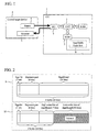
- the embedded control system in the example has a control unit (C/U) 1 provided with a microcomputer.
- the control unit (C/U) 1 has a central processing unit (CPU) 2, a read-only memory (ROM) 3, a memory (RAM), and an input/output unit (I/O) 7.
- Map/table/axis data 8 is stored in the read-only memory 3.
- a control target device 4 has a sensor 5 and an actuator 6.
- a signal from the sensor 5 provided in the control target device 4 is sent to the control unit 1.
- the signal from the sensor 5 is sent to the central processing unit 2 via the input/output unit 7 of the control unit 1.
- the central processing unit 2 performs an interpolation search using the signal from the sensor 5 and the map/table/axis data 8 stored in the read-only memory 3 to generate a control signal.
- the control signal is sent to the actuator 6 of the control target device 4 via the input/output unit 7.
- the control unit 1 may be an on-board engine control unit
- the control target device 4 may be a gasoline-injected internal combustion engine
- the sensor 5 may be an intake air amount sensor or an engine speed sensor
- the actuator 6 may be a fuel injection valve.
- the map/table/axis data 8 may be a three-dimensional map with the X axis set as an intake air amount axis, the Y axis as an engine speed axis, and the Z axis as a fuel injection amount.
- a measured value of the intake air amount is supplied from the intake air amount sensor to the central processing unit 2 and a measured value of the engine speed is supplied from the engine speed sensor to the central processing unit 2.
- the central processing unit 2 calculates the fuel injection amount by an interpolation search on a fuel injection amount map. That is, the fuel injection amount corresponding to measured values of the intake air amount and engine speed is calculated from discrete values on the fuel injection amount map. Data in the floating-point format is used for an interpolation search in the central processing unit 2.
- the central processing unit 2 Based on the fuel injection amount obtained from the interpolation search, the central processing unit 2 generates a signal for controlling the valve opening time of the fuel injection valve.
- the signal is supplied to the gasoline-injected internal combustion engine to control fuel injection.
- control target device 4 may be a gasoline-injected internal combustion engine, but may also be other device, for example, an air conditioner. If the control target device 4 is an air conditioner, the control unit 1 is a controller of the air conditioner. In any case, the present invention is applicable to any embedded control system in which software is installed in hardware in advance.
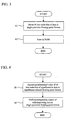
- Examples of data in the floating-point format according to conventional technology and data in the significand-reduced floating-point format according to the present invention will be described with reference to FIG. 2 .
- data 9 in the floating-point format according to conventional technology will be described.
- the data 9 in the floating-point format shows data in the floating-point format conforming to the IEEE 754 standard.
- the data 9 in the floating-point format is data of a total of 4 bytes consisting of the sign bit (1 bit) + the exponent part (8 bits) + the significand (23 bits).
- the data 10 in the significand-reduced floating-point format of the example is data of a total of 2 bytes consisting of the sign bit (1 bit) + the exponent part (8 bits) + the significand (7 bits).
- Comparison of the data 10 in the significand-reduced floating-point format of the example with the data 9 in the floating-point format conforming to the IEEE 754 standard shows that low-order bits of the significand are deleted in the data 10 in the significand-reduced floating-point format of the example.
- a case in which 16 low-order bits of the significand are deleted is shown.
- the 2-byte data 10 in the significand-reduced floating-point format defined by the present invention is obtained by deleting 16 low-order bits of the significand from the 4-byte data 9 in the single-precision floating-point format.
- the present invention is not limited to this.
- the 4-byte data 9 in the single-precision floating-point format 8-byte data in the double-precision floating-point format may be used.
- the 2-byte data 10 in the significand-reduced floating-point format the data 10 in the significand-reduced floating-point format of bytes other than 2 bytes may be generated. As shown in FIG. 2 , a case in which data in the significand-reduced floating-point format is generated using the 4-byte data 9 in the single-precision floating-point format will be described below.
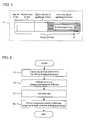
- Processing for changing the data 9 in the single-precision floating-point format to the data 10 in the significand-reduced floating-point format and for storing the data 10 in a memory will be described with reference to FIG. 3 .
- This processing is performed by the central processing unit (CPU) 2.
- CPU central processing unit
- 16 low-order bits of the data 9 in the single-precision floating-point format are deleted at step A1.
- the data 10 in the significand-reduced floating-point format is thereby generated.
- the map/table/axis data 8 defined by the data 10 in the significand-reduced floating-point format is stored in the read-only memory 3 at step A2.
- the data amount is reduced by 50% when compared with a case in which the 4-byte data 9 in the single-precision floating-point format is used. It is assumed, for example, that single-precision floating-point map/table/axis data stored in the read-only memory 3 has a storage capacity of 500 bytes. By using the data 10 in the significand-reduced floating-point format of the example, the storage capacity of 250 bytes can be reduced.
- Processing for bringing back the data 10 in the significand-reduced floating-point format to the data 9 in the single-precision floating-point format and for performing an interpolation search of a table/map will be described with reference to FIG. 4 .
- This processing is performed by the central processing unit (CPU) 2.
- a predetermined value 12 of 16 low-order bits of the significand is appended to the data 10 in the significand-reduced floating-point format at step B 1.
- the data 10 in the significand-reduced floating-point format is thereby brought back to the data 9 in the single-precision floating-point format.
- the predetermined value 12 is any predefined constant.
- the predetermined value 12 may be zero.
- An interpolation search of a table/map is performed using data of the data 9 in the single-precision floating-point format at step B2.
- FIG. 5 shows a state in which the data 9 in the single-precision floating-point format is generated by appending the predetermined value 12 of 16 low-order bits of the significand to the data 10 in the significand-reduced floating-point format.
- a shown in FIG. 5 low-order bits of the significand were deleted when the data 10 in the significand-reduced floating-point format was generated. Therefore, the predetermined value 12 of 16 low-order bits of the significand is appended to generate data of the data 9 in the single-precision floating-point format.
- the predetermined value 12 will be described later. In this manner, the 2-byte data 10 in the significand-reduced floating-point format is converted into the 4-byte data 9 in the single-precision floating-point format.
- the map/table/axis data 8 is defined as data in the fixed-point format and stored in a memory. Therefore, data in the fixed-point format needs to be converted into the data 9 in the single-precision floating-point format in order to perform an interpolation search of the table/map, and physical value conversion data (LSB data and offset data) for the conversion needs to be defined.
- Data in the fixed-point format is converted into data in the single-precision floating-point format at step C1.
- the data in the single-precision floating-point format is multiplied by LSB (least significant bit) data at step C2.
- Offset data is added to the data in the single-precision floating-point format at step C3.
- An interpolation search of the table/map is performed using the data 9 in the single-precision floating-point format at step B2.
- step C1, step C2, and step C3 are needed before performing an interpolation search of the table/map at step B2.
- step B 1 is needed before performing an interpolation search of the table/map at step B2. Therefore, it becomes possible to reduce a computational load.
- FIG. 7 shows a case in which data 13 in the single-precision floating-point format is obtained by appending 0 as the predetermined value 12 to the data 10 in the significand-reduced floating-point format.
- 16 low-order bits of the significand of the data 10 in the significand-reduced floating-point format may be regarded as 0, thereby performing an interpolation search of the table/map.
- step D 1 can be eliminated. Therefore, a computational load can further be reduced. If 0 is appended as the predetermined value 12, an error contained in the data 9 in the single-precision floating-point format restored thereby may become larger. Thus, by using a value other than 0 as the predetermined value 12, an error contained in the restored data 9 in the single-precision floating-point format can be made smaller.
- the predetermined value 12 is appended to 16 low-order bits of the significand of the data 10 in the significand-reduced floating-point format.
- data 14 and 15 in the significand-reduced floating-point format of the example it is assumed that the predetermined value 12 is a value corresponding to half the maximum value that can be taken by the predetermined value 12. If, for example, the maximum value that can be taken by the predetermined value 12 is 65535, half the maximum value can be 32767 or 32768.
- the predetermined value 12 is 32767.
- This number is represented in binary notation as a number of 1 followed by 15 0s and in hexadecimal notation as 0 x 8000.
- the predetermined value 12 is 32768. This number is represented in binary notation as a number of 0 followed by 15 1s and in hexadecimal notation as 0 x 7FFF.
- 16 low-order bits of the significand whose highest-order bit is 1 and other bits are 0 are appended to the data 10 in the significand-reduced floating-point format at step E1.
- the data 10 in the significand-reduced floating-point format is thereby converted into the data 14 in the single-precision floating-point format in FIG. 9 .
- An interpolation search of the table/map is performed using the data 14 in the single-precision floating-point format at step B2.
- 16 low-order bits of the significand whose highest-order bit is 0 and other bits are 1 are appended to the data 10 in the significand-reduced floating-point format at step F1.
- the data 10 in the significand-reduced floating-point format is thereby converted into the data 15 in the single-precision floating-point format in FIG. 9 .
- An interpolation search of the table/map is performed using the data 15 in the single-precision floating-point format at step B2.
- the predetermined value to be appended to 16 low-order bits of the significand of the data 10 in the significand-reduced floating-point format is set to a value about half the maximum value that can be taken by the predetermined value, as described above, an error contained in the restored data 9 in the single-precision floating-point format is made smaller. Therefore, a rounding error that occurs when the data 10 in the significand-reduced floating-point format is stored in the read-only memory 3 can be normalized.
- FIG. 12 Another example of generating data in the significand-reduced floating-point format will be described with reference to FIG. 12 .
- 16 low-order bits of the significand are deleted and at this point, the value of a highest-order bit 18 (1 bit) of low-order bits (16 bits) of the significand is used to change the value of high-order bits 17 (7 bits) of the significand.
- the flowchart at this point is shown in FIG. 13 .
- bit value of the highest-order bit 18 (1 bit) of low-order bits (16 bits) of the significand of the data 9 in the single-precision floating-point format is set as X at step 19.
- step 21 1 is added to the high-order bits 17 of the significand.
- the processing terminates without changing the high-order bits 17 of the significand.
- an error between the restored data 9 in the single-precision floating-point format and the original data 9 in the single-precision floating-point format is considered to be small even if 0 is appended as the predetermined value 12.
- the embedded control system in the example has the control unit (C/U) 1 provided with a microcomputer.
- the control unit (C/U) 1 has the central processing unit (CPU) 2, the read-only memory (ROM) 3, a random access memory (RAM) 26, a backup memory 24, and the input/output unit (I/O) 7.
- the map/table/axis data 8 is stored in the read-only memory 3.
- An input signal or data 27 calculated in the process of operation is temporarily stored in the random access memory (RAM) 26. However, the data 27 is deleted with power-off.
- saved data 25 that is identical to the data 27 is always stored in the backup memory 24. When power is turned on next time, the saved data 25 stored in the backup memory 24 is used.
- the backup memory 24 may be a RAM always energized by a power supply or an erasable programmable read-only memory or a flash memory.
- the data 27 stored in the random access memory (RAM) 26 is the 4-byte data 9 in the single-precision floating-point format.
- the data 9 is converted into the 2-byte data 10 in the significand-reduced floating-point format to be the saved data 25.
- the 2-byte data 10 in the significand-reduced floating-point format is stored in the backup memory 24.
- the saved data 25 stored in the backup memory 24 is read to perform an operation thereon, the data 10 is brought back to the data 9 in the single-precision floating-point format.
- the method of bringing back the data 10 to the 4-byte data 9 in the single-precision floating-point format is already described above. That is, the predetermined value 12 is substituted into 16 low-order bits of the significand.
- the flowchart at this point is shown in FIG. 15 .
- FIG. 15 will be described below.
- Low-order bits of the significand of the calculated data 27 in the single-precision floating-point format stored in the random access memory 26 are deleted at step G 1.
- Data in the significand-reduced floating-point format is thereby obtained.
- Saved data 28 in the significand-reduced floating-point format is stored in the backup memory 24 at step G2.
- a predetermined value is appended to low-order bits of the significand of the saved data 28 stored in the backup memory 24 at step G3.
- the data 9 in the single-precision floating-point format is thereby restored.
- An interpolation search of the table/map is performed using the data 9 in the single-precision floating-point format at step B2.
- the saved data 25 in the single-precision floating-point format is 100-byte data
- the data 10 in the significand-reduced floating-point format stored in the backup memory 24 becomes 50-byte data so that the storage capacity of 50 bytes can be reduced.
- Offset data is subtracted from the calculated data 27 in the single-precision floating-point format stored in the random access memory 26 at step H1.
- the calculated data 27 after the subtraction is divided by LSB at step H2.
- the calculated data 27 after the subtraction and division is converted into data in the fixed-point format at step H3.
- the saved data 25 in the fixed-point format is stored in the backup memory 24 at step G2.
- the saved data 28 stored in the backup memory 24 is converted into data in the single-precision floating-point format at step C1.
- the data in the single-precision floating-point format is multiplied by the LSB data at step C2.
- the offset data is added to the data after the multiplication at step C3.
- An interpolation search of the table/map is performed using the data 9 in the single-precision floating-point format at step B2.
- the conventional technology shown in FIG. 16 needs three steps of step H1, step H2, and step H3 before data is stored in the backup memory 24. According to the present invention shown in FIG. 15 , on the other hand, only one step of step G1 is needed. Thus, a computational load can be reduced.
- the conventional technology shown in FIG. 16 also needs three steps of step C1, step C2, and step C3 before an interpolation search of the table/map being performed using saved data stored in the backup memory 24. According to the present invention, on the other hand, only one step of step G3 is needed. Therefore, a computational load can be reduced.
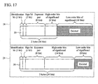
- the data 28 in the significand-reduced floating-point format of the example is data of a total of 2 bytes consisting of the identification bit (1 bit) + the sign bit (1 bit) + the exponent part (8 bits) + high-order bits (6 bits) of the significand.
- the data 28 in the significand-reduced floating-point format of the example is obtained by both appending the identification bit (1 bit) to the head of the 4-byte data 9 in the single-precision floating-point format shown in FIG. 2 and deleting 16 low-order bits of the significand.
- the data 29 in the significand-reduced floating-point format of the example is data of a total of 3 bytes consisting of the identification bit (1 bit) + the sign bit (1 bit) + the exponent part (8 bits) + high-order bits (14 bits) of the significand.
- the data 29 in the significand-reduced floating-point format of the example is obtained by both appending the identification bit (1 bit) to the head of the 4-byte data 9 in the single-precision floating-point format shown in FIG. 2 and deleting 8 low-order bits of the significand.
- the identification bit (1 bit) shows the type of data in the significand-reduced floating-point format, that is, the number of bytes. If, for example, the value of an identification bit 30 is "0", the 2-byte data 28 in the significand-reduced floating-point format is indicated, and if the value of the identification bit 30 is "1", the 3-byte data 29 in the significand-reduced floating-point format is indicated. By reading the value of the identification bit 30 at the head of data, the central processing unit 2 can know whether data is 2-byte data in the significand-reduced floating-point format or 3-byte data in the significand-reduced floating-point format.
- the map/table/axis data 8 contains two types of the data 28 and 29 in the significand-reduced floating-point format shown in FIG. 17 .
- the 2-byte data 28 in the significand-reduced floating-point format can reduce the storage capacity of the read-only memory 3 since the amount of data thereof is relatively small. However, accuracy of arithmetic using the data 28 is relatively low.
- the 3-byte data 29 in the significand-reduced floating-point format cannot reduce the storage capacity of the read-only memory 3 since the amount of data thereof is relatively large. However, accuracy of arithmetic using the data 29 is relatively high.
- the 2-byte data 28 in the significand-reduced floating-point format is used, and when higher priority should be given to arithmetic precision, the 3-byte data 29 in the significand-reduced floating-point format is used.
- the read-only memory 3 has the map/table/axis data 8 including two types of data of the data 28 and 29 in the significand-reduced floating-point format stored therein.
- the 2-byte data 28 in the significand-reduced floating-point format and the 3-byte data 29 in the significand-reduced floating-point format are arranged in random order.
- the central processing unit 2 reads data in units of 3 bytes from the head of the data array 31. In the first readout, the central processing unit 2 reads 3-byte data.
- the central processing unit 2 reads the identification bit at the head of the 3 bytes and determines that the read data is the 3-byte data 29 in the significand-reduced floating-point format. This will be first data to be used 33.
- the data to be used 33 consists of the 3-byte data 29 in the significand-reduced floating-point format. A predetermined value of 8 low-order bits is appended to the 3-byte data to be used. 4-byte data is obtained by this 4-byte conversion 34.
- the central processing unit 2 reads 3-byte data.
- the central processing unit 2 reads the identification bit of the 3 bytes and identifies that the read data is the 2-byte data 28 in the significand-reduced floating-point format. Therefore, the central processing unit 2 determines that the read 3-byte data contains, in addition to the 2-byte data 28 in the significand-reduced floating-point format, 1-byte unnecessary data. Thus, 1-byte data at the back of the read 3-byte data is deleted.
- the data to be used 33 consists of the 2-byte data 28 in the significand-reduced floating-point format. A predetermined value of 16 low-order bits is appended to the 2-byte data to be used. 4-byte data is obtained by the 4-byte conversion 34.
- Initialization processing is performed at step 35. That is, the start address of map/table/axis data is substituted into a data address A. 3-byte data from the address indicated by the data address A is read at step 36 to substitute the data into a temporary variable X. This corresponds to read data 32 in FIG. 18 .
- the identification bit 30 is read from data contained in the temporary variable X at step 37. If the identification bit 30 is "0", processing proceeds to step 38. That is, the read data is the 2-byte data 28 in the significand-reduced floating-point format. If the identification bit 30 is "1”, processing proceeds to step 42. That is, the read data is the 3-byte data 29 in the significand-reduced floating-point format.
- Steps 38 to 40 correspond to processing when the read data is the 2-byte data 28 in the significand-reduced floating-point format. 2 is added to the data address A for the next readout processing at step 38.
- step 39 first 2 bytes of 3-byte data X are substituted into data Y to be returned by the subroutine. This corresponds to the second data to be used 33 in FIG. 18 .
- a predetermined value of 16 low-order bits is appended to the data Y at step 40.
- the data Y thereby becomes 4-byte data. This corresponds to the second 4-byte conversion 34.
- Steps 42 to 44 correspond to processing when the read data is the 3-byte data 29 in the significand-reduced floating-point format. 3 is added to the data address A for the next readout processing at step 42. 3-byte data X is substituted into the data Y at step 43. This corresponds to the first data to be used 33 in FIG. 18 . A predetermined value of 8 low-order bits is appended to the data Y at step 44. The data Y thereby becomes 4-byte data. This corresponds to the first 4-byte conversion 34.
- a loop counter is referenced at step 41 in order to determine whether or not the current data is the target data. If the current data is the target data, processing proceeds to step 45 to set the data Y as the return value before terminating the subroutine. If it is determined at step 41 that the target data has not been reached, processing returns to step 36 to repeat subsequent steps.
- the identification bit 30 will at least have 2 bits.
- the identification bit 30 is appended to the first bit of data in the significand-reduced floating-point format.
- the identification bit 30 may be appended to anywhere of data in the significand-reduced floating-point format.
- the central processing unit 2 reads data in units of 3 bytes from the head of the data array 31. Therefore, the identification bit 30 needs only to be included in the 3 bytes from the head of the read data.
- the identification bit 30 is preferably appended to the head of data in the significand-reduced floating-point format. In this case, the type of data can be identified by reading only the first 1 byte. Processing can thereby be made faster.
Landscapes
- Engineering & Computer Science (AREA)
- General Physics & Mathematics (AREA)
- Theoretical Computer Science (AREA)
- Physics & Mathematics (AREA)
- Mathematical Optimization (AREA)
- Mathematical Analysis (AREA)
- Computing Systems (AREA)
- Pure & Applied Mathematics (AREA)
- General Engineering & Computer Science (AREA)
- Computational Mathematics (AREA)
- Nonlinear Science (AREA)
- Compression, Expansion, Code Conversion, And Decoders (AREA)
- Complex Calculations (AREA)
- Image Processing (AREA)
Applications Claiming Priority (1)
| Application Number | Priority Date | Filing Date | Title |
|---|---|---|---|
| JP2008091632A JP4629750B2 (ja) | 2008-03-31 | 2008-03-31 | 組み込み制御装置 |
Publications (3)
| Publication Number | Publication Date |
|---|---|
| EP2112591A2 true EP2112591A2 (fr) | 2009-10-28 |
| EP2112591A3 EP2112591A3 (fr) | 2011-02-16 |
| EP2112591B1 EP2112591B1 (fr) | 2012-12-19 |
Family
ID=41066105
Family Applications (1)
| Application Number | Title | Priority Date | Filing Date |
|---|---|---|---|
| EP09001842A Not-in-force EP2112591B1 (fr) | 2008-03-31 | 2009-02-10 | Système de commande intégré |
Country Status (4)
| Country | Link |
|---|---|
| US (1) | US8484266B2 (fr) |
| EP (1) | EP2112591B1 (fr) |
| JP (1) | JP4629750B2 (fr) |
| CN (1) | CN101551740B (fr) |
Cited By (3)
| Publication number | Priority date | Publication date | Assignee | Title |
|---|---|---|---|---|
| GB2539265A (en) * | 2015-06-12 | 2016-12-14 | Advanced Risc Mach Ltd | Apparatus and method for controlling rounding when performing a floating point operation |
| GB2488322B (en) * | 2011-02-22 | 2017-09-20 | Advanced Risc Mach Ltd | Number format pre-conversion instructions |
| EP3651017A3 (fr) * | 2018-11-09 | 2020-06-24 | INTEL Corporation | Systèmes et procédés permettant d'effectuer des instructions de produit à points de matrice 16 bits à virgule flottante |
Families Citing this family (6)
| Publication number | Priority date | Publication date | Assignee | Title |
|---|---|---|---|---|
| US10289412B2 (en) * | 2012-02-09 | 2019-05-14 | Qualcomm Incorporated | Floating point constant generation instruction |
| DE102015000259B4 (de) | 2015-01-16 | 2016-12-29 | Cayago Gmbh | Schwimm- und Tauchhilfe |
| CN107038016B (zh) * | 2017-03-29 | 2019-11-15 | 广州酷狗计算机科技有限公司 | 一种基于gpu的浮点数转换方法及装置 |
| US11017291B2 (en) * | 2017-04-28 | 2021-05-25 | Intel Corporation | Training with adaptive runtime and precision profiling |
| CN112558918B (zh) * | 2020-12-11 | 2022-05-27 | 北京百度网讯科技有限公司 | 用于神经网络的乘加运算方法和装置 |
| JP2023127942A (ja) * | 2022-03-02 | 2023-09-14 | 富士通株式会社 | 演算処理装置及びメモリアクセス方法 |
Citations (1)
| Publication number | Priority date | Publication date | Assignee | Title |
|---|---|---|---|---|
| JP2004225668A (ja) | 2003-01-27 | 2004-08-12 | Denso Corp | 電子制御装置及び該電子制御装置の記憶装置 |
Family Cites Families (24)
| Publication number | Priority date | Publication date | Assignee | Title |
|---|---|---|---|---|
| JPS5776634A (en) * | 1980-10-31 | 1982-05-13 | Hitachi Ltd | Digital signal processor |
| US6643765B1 (en) * | 1995-08-16 | 2003-11-04 | Microunity Systems Engineering, Inc. | Programmable processor with group floating point operations |
| US5696710A (en) * | 1995-12-29 | 1997-12-09 | Thomson Consumer Electronics, Inc. | Apparatus for symmetrically reducing N least significant bits of an M-bit digital signal |
| US6601079B1 (en) * | 1997-12-29 | 2003-07-29 | Intel Corporation | Converting between different floating point exponent representations |
| US6105129A (en) * | 1998-02-18 | 2000-08-15 | Advanced Micro Devices, Inc. | Converting register data from a first format type to a second format type if a second type instruction consumes data produced by a first type instruction |
| US6253312B1 (en) * | 1998-08-07 | 2001-06-26 | Ip First, L.L.C. | Method and apparatus for double operand load |
| US6212539B1 (en) * | 1998-10-10 | 2001-04-03 | Institute For The Development Of Emerging Architectures, L.L.C. | Methods and apparatus for handling and storing bi-endian words in a floating-point processor |
| JP2000182072A (ja) * | 1998-12-11 | 2000-06-30 | Hitachi Ltd | データ記録媒体、データプロセッサ及び描画情報演算方法 |
| JP2000293494A (ja) * | 1999-04-09 | 2000-10-20 | Fuji Xerox Co Ltd | 並列計算装置および並列計算方法 |
| US6487653B1 (en) * | 1999-08-25 | 2002-11-26 | Advanced Micro Devices, Inc. | Method and apparatus for denormal load handling |
| US7092803B2 (en) * | 2000-08-18 | 2006-08-15 | Idsc Holdings, Llc | Remote monitoring, configuring, programming and diagnostic system and method for vehicles and vehicle components |
| US7330864B2 (en) * | 2001-03-01 | 2008-02-12 | Microsoft Corporation | System and method for using native floating point microprocessor instructions to manipulate 16-bit floating point data representations |
| US8214655B2 (en) * | 2002-03-29 | 2012-07-03 | Kabushiki Kaisha Toshiba | Data structure of multimedia file format, encrypting method and device thereof, and decrypting method and device thereof |
| US7188133B2 (en) * | 2002-06-20 | 2007-03-06 | Matsushita Electric Industrial Co., Ltd. | Floating point number storage method and floating point arithmetic device |
| US7236995B2 (en) * | 2002-12-27 | 2007-06-26 | Arm Limited | Data processing apparatus and method for converting a number between fixed-point and floating-point representations |
| US7290024B2 (en) * | 2003-12-18 | 2007-10-30 | Intel Corporation | Methods and apparatus for performing mathematical operations using scaled integers |
| US7305295B2 (en) * | 2004-04-23 | 2007-12-04 | General Motors Corporation | Throttle limiting for an internal combustion engine |
| JP4837305B2 (ja) * | 2005-05-10 | 2011-12-14 | ルネサスエレクトロニクス株式会社 | マイクロプロセッサ及びマイクロプロセッサの制御方法 |
| US7406589B2 (en) * | 2005-05-12 | 2008-07-29 | International Business Machines Corporation | Processor having efficient function estimate instructions |
| US7533575B2 (en) * | 2006-02-03 | 2009-05-19 | Jentek Sensors, Inc. | Quasistatic magnetic and electric field stress/strain gages |
| JP4413198B2 (ja) * | 2006-03-23 | 2010-02-10 | 富士通株式会社 | 浮動小数点データの総和演算処理方法及びコンピュータシステム |
| US7797360B2 (en) * | 2006-04-06 | 2010-09-14 | Sap Ag | Sortable floating point numbers |
| EP1916603A1 (fr) * | 2006-10-23 | 2008-04-30 | Codenomicon Ltd. | Procédé et dispositif pour localiser des frontières de domaine d'entrée |
| US8103946B2 (en) * | 2007-05-18 | 2012-01-24 | GM Global Technology Operations LLC | Secure data strategy for vehicle control systems |
-
2008
- 2008-03-31 JP JP2008091632A patent/JP4629750B2/ja not_active Expired - Fee Related
-
2009
- 2009-02-10 EP EP09001842A patent/EP2112591B1/fr not_active Not-in-force
- 2009-02-19 US US12/389,161 patent/US8484266B2/en not_active Expired - Fee Related
- 2009-02-20 CN CN2009100049341A patent/CN101551740B/zh not_active Expired - Fee Related
Patent Citations (1)
| Publication number | Priority date | Publication date | Assignee | Title |
|---|---|---|---|---|
| JP2004225668A (ja) | 2003-01-27 | 2004-08-12 | Denso Corp | 電子制御装置及び該電子制御装置の記憶装置 |
Cited By (12)
| Publication number | Priority date | Publication date | Assignee | Title |
|---|---|---|---|---|
| GB2488322B (en) * | 2011-02-22 | 2017-09-20 | Advanced Risc Mach Ltd | Number format pre-conversion instructions |
| US10331404B2 (en) | 2011-02-22 | 2019-06-25 | Arm Limited | Number format pre-conversion instructions |
| GB2539265A (en) * | 2015-06-12 | 2016-12-14 | Advanced Risc Mach Ltd | Apparatus and method for controlling rounding when performing a floating point operation |
| US10338889B2 (en) | 2015-06-12 | 2019-07-02 | Arm Limited | Apparatus and method for controlling rounding when performing a floating point operation |
| GB2539265B (en) * | 2015-06-12 | 2020-07-29 | Advanced Risc Mach Ltd | Apparatus and method for controlling rounding when performing a floating point operation |
| EP3651017A3 (fr) * | 2018-11-09 | 2020-06-24 | INTEL Corporation | Systèmes et procédés permettant d'effectuer des instructions de produit à points de matrice 16 bits à virgule flottante |
| US10963246B2 (en) | 2018-11-09 | 2021-03-30 | Intel Corporation | Systems and methods for performing 16-bit floating-point matrix dot product instructions |
| EP4002105A1 (fr) * | 2018-11-09 | 2022-05-25 | Intel Corporation | Systèmes et procédés permettant d'effectuer des instructions de produit à points de matrice 16 bits à virgule flottante |
| US11614936B2 (en) | 2018-11-09 | 2023-03-28 | Intel Corporation | Systems and methods for performing 16-bit floating-point matrix dot product instructions |
| US11893389B2 (en) | 2018-11-09 | 2024-02-06 | Intel Corporation | Systems and methods for performing 16-bit floating-point matrix dot product instructions |
| EP4276609A3 (fr) * | 2018-11-09 | 2024-02-14 | Intel Corporation | Systèmes et procédés pour effectuer des instructions de produit de points matriciels à virgule flottante à 16 bits |
| US12307250B2 (en) | 2018-11-09 | 2025-05-20 | Intel Corporation | Systems and methods for performing 16-bit floating-point matrix dot product instructions |
Also Published As
| Publication number | Publication date |
|---|---|
| JP4629750B2 (ja) | 2011-02-09 |
| EP2112591A3 (fr) | 2011-02-16 |
| CN101551740B (zh) | 2011-12-28 |
| JP2009245212A (ja) | 2009-10-22 |
| CN101551740A (zh) | 2009-10-07 |
| EP2112591B1 (fr) | 2012-12-19 |
| US20090249040A1 (en) | 2009-10-01 |
| US8484266B2 (en) | 2013-07-09 |
Similar Documents
| Publication | Publication Date | Title |
|---|---|---|
| EP2112591B1 (fr) | Système de commande intégré | |
| US5892697A (en) | Method and apparatus for handling overflow and underflow in processing floating-point numbers | |
| CN114919418B (zh) | 滑行能量回收控制方法、装置、可读存储介质及电子设备 | |
| JPH05324270A (ja) | 浮動小数点数のためのフォーマット変換方法及びその装置 | |
| US7558811B2 (en) | Electronic control apparatus and memory apparatus for electronic control apparatus | |
| JP3551875B2 (ja) | 浮動小数点演算機能を有した電子制御装置 | |
| JP4329332B2 (ja) | 電子制御装置及び制御プログラム | |
| CN115146769B (zh) | 一种基于范围可寻址查找表计算tanh函数的数字电路模块 | |
| US20150012574A1 (en) | Model calculation unit and control unit for calculating a data-based function model having data in various number formats | |
| JP2004278483A (ja) | 浮動小数点演算機能を有する電子制御装置 | |
| WO2023116400A1 (fr) | Procédé d'opération vectorielle, opérateur vectoriel, dispositif électronique et support de stockage | |
| US7321914B2 (en) | Fast method for calculating powers of two as a floating point data type | |
| CN100410871C (zh) | 应用跳跃式浮点数运算法的数字讯号处理器 | |
| JP4868408B2 (ja) | 演算装置、逆数の近似計算プログラムおよび近似計算方法 | |
| CN118498474B (zh) | 挖掘机回转控制方法和系统以及挖掘机 | |
| CN121009930B (zh) | 激活函数计算电路、方法和系统 | |
| JP2001282505A (ja) | 浮動小数点演算機能を有した電子制御装置 | |
| JP3688503B2 (ja) | プログラマブルコントローラ | |
| JP2000305750A (ja) | 車載用電子制御装置 | |
| CN117707471A (zh) | 环境采集设备和目标设备及其数据处理方法、系统 | |
| US7181645B2 (en) | Method and apparatus for storing main data with two checkup data | |
| JP5040710B2 (ja) | 電子制御装置、及び電子制御装置における演算方法 | |
| JP2008152801A (ja) | 浮動小数点演算機能を有する電子制御装置 | |
| KR20070025195A (ko) | 고속 구현 및 정확도 향상을 위한 역제곱근 연산방법 | |
| JP2001184192A (ja) | 浮動小数点演算機能を有した電子制御装置 |
Legal Events
| Date | Code | Title | Description |
|---|---|---|---|
| PUAI | Public reference made under article 153(3) epc to a published international application that has entered the european phase |
Free format text: ORIGINAL CODE: 0009012 |
|
| 17P | Request for examination filed |
Effective date: 20090210 |
|
| AK | Designated contracting states |
Kind code of ref document: A2 Designated state(s): AT BE BG CH CY CZ DE DK EE ES FI FR GB GR HR HU IE IS IT LI LT LU LV MC MK MT NL NO PL PT RO SE SI SK TR |
|
| AX | Request for extension of the european patent |
Extension state: AL BA RS |
|
| RIC1 | Information provided on ipc code assigned before grant |
Ipc: H03M 7/30 20060101ALI20100624BHEP Ipc: G06F 1/035 20060101ALI20100624BHEP Ipc: G06F 7/483 20060101AFI20100624BHEP Ipc: H03M 7/24 20060101ALI20100624BHEP |
|
| PUAL | Search report despatched |
Free format text: ORIGINAL CODE: 0009013 |
|
| AK | Designated contracting states |
Kind code of ref document: A3 Designated state(s): AT BE BG CH CY CZ DE DK EE ES FI FR GB GR HR HU IE IS IT LI LT LU LV MC MK MT NL NO PL PT RO SE SI SK TR |
|
| AX | Request for extension of the european patent |
Extension state: AL BA RS |
|
| AKX | Designation fees paid |
Designated state(s): DE FR GB IT |
|
| 17Q | First examination report despatched |
Effective date: 20111102 |
|
| GRAP | Despatch of communication of intention to grant a patent |
Free format text: ORIGINAL CODE: EPIDOSNIGR1 |
|
| GRAS | Grant fee paid |
Free format text: ORIGINAL CODE: EPIDOSNIGR3 |
|
| GRAA | (expected) grant |
Free format text: ORIGINAL CODE: 0009210 |
|
| AK | Designated contracting states |
Kind code of ref document: B1 Designated state(s): DE FR GB IT |
|
| REG | Reference to a national code |
Ref country code: GB Ref legal event code: FG4D |
|
| RIN1 | Information on inventor provided before grant (corrected) |
Inventor name: FUJIMOTO, SHINYA Inventor name: OHKAWA, KEIICHIRO |
|
| REG | Reference to a national code |
Ref country code: DE Ref legal event code: R096 Ref document number: 602009011973 Country of ref document: DE Effective date: 20130214 |
|
| PLBE | No opposition filed within time limit |
Free format text: ORIGINAL CODE: 0009261 |
|
| STAA | Information on the status of an ep patent application or granted ep patent |
Free format text: STATUS: NO OPPOSITION FILED WITHIN TIME LIMIT |
|
| REG | Reference to a national code |
Ref country code: FR Ref legal event code: ST Effective date: 20131031 |
|
| 26N | No opposition filed |
Effective date: 20130920 |
|
| GBPC | Gb: european patent ceased through non-payment of renewal fee |
Effective date: 20130319 |
|
| PG25 | Lapsed in a contracting state [announced via postgrant information from national office to epo] |
Ref country code: IT Free format text: LAPSE BECAUSE OF FAILURE TO SUBMIT A TRANSLATION OF THE DESCRIPTION OR TO PAY THE FEE WITHIN THE PRESCRIBED TIME-LIMIT Effective date: 20121219 |
|
| REG | Reference to a national code |
Ref country code: DE Ref legal event code: R097 Ref document number: 602009011973 Country of ref document: DE Effective date: 20130920 |
|
| PG25 | Lapsed in a contracting state [announced via postgrant information from national office to epo] |
Ref country code: GB Free format text: LAPSE BECAUSE OF NON-PAYMENT OF DUE FEES Effective date: 20130319 Ref country code: FR Free format text: LAPSE BECAUSE OF NON-PAYMENT OF DUE FEES Effective date: 20130228 |
|
| PGFP | Annual fee paid to national office [announced via postgrant information from national office to epo] |
Ref country code: DE Payment date: 20210126 Year of fee payment: 13 |
|
| REG | Reference to a national code |
Ref country code: DE Ref legal event code: R119 Ref document number: 602009011973 Country of ref document: DE |
|
| PG25 | Lapsed in a contracting state [announced via postgrant information from national office to epo] |
Ref country code: DE Free format text: LAPSE BECAUSE OF NON-PAYMENT OF DUE FEES Effective date: 20220901 |