EP2112640B1 - Terminal d'un système de commande radio en continu - Google Patents
Terminal d'un système de commande radio en continu Download PDFInfo
- Publication number
- EP2112640B1 EP2112640B1 EP08103685A EP08103685A EP2112640B1 EP 2112640 B1 EP2112640 B1 EP 2112640B1 EP 08103685 A EP08103685 A EP 08103685A EP 08103685 A EP08103685 A EP 08103685A EP 2112640 B1 EP2112640 B1 EP 2112640B1
- Authority
- EP
- European Patent Office
- Prior art keywords
- processing
- control
- terminal according
- information
- unit
- Prior art date
- Legal status (The legal status is an assumption and is not a legal conclusion. Google has not performed a legal analysis and makes no representation as to the accuracy of the status listed.)
- Active
Links
Images


Classifications
-
- G—PHYSICS
- G08—SIGNALLING
- G08C—TRANSMISSION SYSTEMS FOR MEASURED VALUES, CONTROL OR SIMILAR SIGNALS
- G08C17/00—Arrangements for transmitting signals characterised by the use of a wireless electrical link
- G08C17/02—Arrangements for transmitting signals characterised by the use of a wireless electrical link using a radio link
-
- G—PHYSICS
- G08—SIGNALLING
- G08C—TRANSMISSION SYSTEMS FOR MEASURED VALUES, CONTROL OR SIMILAR SIGNALS
- G08C2201/00—Transmission systems of control signals via wireless link
- G08C2201/30—User interface
- G08C2201/33—Remote control using macros, scripts
-
- G—PHYSICS
- G08—SIGNALLING
- G08C—TRANSMISSION SYSTEMS FOR MEASURED VALUES, CONTROL OR SIMILAR SIGNALS
- G08C2201/00—Transmission systems of control signals via wireless link
- G08C2201/50—Receiving or transmitting feedback, e.g. replies, status updates, acknowledgements, from the controlled devices
- G08C2201/51—Remote controlling of devices based on replies, status thereof
-
- G—PHYSICS
- G08—SIGNALLING
- G08C—TRANSMISSION SYSTEMS FOR MEASURED VALUES, CONTROL OR SIMILAR SIGNALS
- G08C2201/00—Transmission systems of control signals via wireless link
- G08C2201/60—Security, fault tolerance
- G08C2201/61—Password, biometric
Definitions
- the invention relates to a terminal of a radio ripple control system.
- the invention has for its object to provide a terminal of such a system, which is more versatile than the terminals used in previous systems and in particular can provide extended uses for private users.
- the invention includes the idea of a combined processing of received information, which was imprinted in a radio ripple control telegram on a long-wave carrier, and locally detected at the terminal or entered there or stored there information. It further includes the idea of providing a control signal obtained as a result of the processing at a suitable output interface of the terminal. Finally, the invention includes the idea of providing a display device connected to the processing unit for displaying the processing result, specifically information relating to the generated control signal.
- a terminal designed in this way can fulfill tasks which go beyond the previous uses, and open up systems of radio ripple control, such as the EFR system (European Radio Ground Control), novel applications and user groups, including private users and applications in the building or leisure sector.
- radio ripple control such as the EFR system (European Radio Ground Control)
- novel applications and user groups including private users and applications in the building or leisure sector.
- an information separating device for separating control information and supplementary information transmitted time-sequentially in a ripple control telegram containing the control information of an internal processing and at least a part of the supplementary information of the display unit supplies.
- Such a terminal can easily process ripple telegrams, which provide both exclusively processing-relevant data for triggering control operations by the terminal and exclusively display-relevant data for the information supply of a user or operator.
- ripple telegrams which provide both exclusively processing-relevant data for triggering control operations by the terminal and exclusively display-relevant data for the information supply of a user or operator.
- This can for example be designed so that in addition to load control data for cost-effective control of an electrical load in a ripple control telegram Weather data are transmitted at the location of the terminal and the terminal separates both types of data and the load control data processing for obtaining a local control signal, but the weather data directly to a display unit supplies.
- the processing device is assigned a decryption unit which is designed to decrypt information encrypted on the transmitter side, in particular supplementary information, by means of a key internally stored in the terminal or transmitted in a separate data telegram and supplied via the receiving unit of the decryption unit is.
- the decryption unit may be installed in the terminal or - as typically decoders of pay-TV systems to supplement an existing television - be provided.
- the key can be provided in many different ways, and for certain methods it may be useful for the decryption unit to have an input device for manually entering a key provided on a separate channel.
- the terminal may also include an input unit, which is connected to a data and / or program memory of the processing unit and / or an input of the display device, for the manual input of processing-relevant and / or display-relevant data and / or control commands.
- This may, for example, allow the operator of a private heating system to enter on-site control variables, such as a target room temperature or a daytime temperature profile, for a combined processing with centrally retrieved control variables, such as temperature forecast values or tariff data.
- the input unit can be conventional input means, such as a keyboard or a touch screen, but also a standard interface for connection a local PC or PDA or speech recognition means for recognizing spoken control data or commands.
- the input unit connected to an input of the processing and / or display unit also serves as an input unit of the decryption device in order to input an access code to the data provided in the system.
- the processing device is assigned a plurality of program memory areas which store a plurality of processing algorithms, in particular cost calculation programs, and a plurality of data memory areas.
- the latter can store which particular at least one plurality of energy tariffs, wherein at least each of the data storage areas can be addressed via a signal obtained from a ripple control telegram.
- Such an advantageous structure makes it possible to initiate complex calculations based on locally stored data and algorithms with simple addressing commands transmitted in a ripple control telegram which communicate the current status of a flexible tariff structure to the users.
- a specific device operation can be optimized locally with regard to the currently applicable tariffs or different control variants can be cost-effectively calculated and the results displayed to the user. He can then compare the different calculated variants and make his decision by manually selecting one of the possible control modes.
- control signal output interface is designed to provide a plurality of mutually independent control signals, which are provided with a coding for targeted control of a specific connected or connectable consumer.
- a terminal is suitable as a control center (or component thereof) for a complex home automation or lighting system, in which Although all components are to be controlled based on data or control signals from the system center of the radio ripple control system, but in a differentiated manner.
- the processing unit a consumer parameter memory for storing connection or consumption parameters associated with at least one connected or connectable consumer.
- the term "consumer” is understood here in general to mean any device controllable via the terminal according to the invention or any device combination or technical system. Examples include a lighting device or installation, such as a complete outdoor and garden lighting of a private user or a street lighting system (or parts thereof) of a municipal user, a boiler of a family house or a flat or a heating system of a building or housing complex, a charging station for the batteries of an electric car or similar
- the consumer parameter memory may have a plurality of memory areas each assigned to a consumer, in which the consumer or load parameters are stored in association with a consumer code. This sensibly serves at the same time for coding a control signal output by the processing unit for the respective consumer.
- the processing device has a display control unit for controlling a specific display of the control signals coded for individual consumers and optionally of associated consumer parameters and optionally of the respective consumer Following processing results can be displayed, intermediate and final results of the processing can be displayed in a differentiated manner to the operator or user in order to facilitate his decisions for the operational control of the corresponding installation.
- the processing unit has at least one threshold arbitrator for threshold value processing of a tariff signal received in a ripple control telegram with a threshold value stored in an internal data storage area. This serves to provide a control signal dependent on the relation between the tariff signal and the threshold value at the control signal output interface.
- This design allows threshold-oriented control of connected devices or equipment in response to current tariff data transmitted via the radio ripple control system, such as a shutdown or partial shutdown of consumers when currently exceeding a certain cost size.
- the display device has an alarm display area which is signal-connected to the threshold value discriminator for outputting an alarm display in parallel with the provision of a control signal which triggers the disconnection of a consumer. In this way, the operator or user can signal the imminent or completed shutdown or partial shutdown of a consumer and be given the opportunity for a manual intervention in this control process.
- the processing unit has a reset input, which is connected on the input side to the input unit of the processing unit and to which the output of a control signal effecting the deactivation of a consumer can be manually canceled at the control signal output interface.
- a further embodiment of the invention consists in that the processing device has a measured value input for connection to at least one local sensor or measuring device, in particular a temperature sensor and / or a lighting sensor and / or an energy consumption measuring device, and for direct feeding of the acquired measured values into a processing operation having.
- a terminal is able to feed into the processing locally detectable and included in the generation of control signals measurements of quantities that reflect environmental conditions or system states.
- Fig. 1 schematically shows a radio ripple control system 1 with a radio ripple control center 3, which sends 5 ripple control telegrams 7a to 7c to three system terminals 9a, 9b and 9c via a long-wave transmitter.
- the terminals 9a to 9c receive the respective ripple control telegrams 7a to 7c and process them in a manner described in more detail above and below for obtaining a processing result, in particular a control signal.
- the terminal 9a is assigned, on the output side, a home heating system 11a to be controlled via the corresponding control signal as a load, and in a similar manner the terminal 9b is assigned a lighting system 11b to be controlled with the control signal obtained here.
- the ripple control telegram 7a has a first telegram section 7a.1, which comprises uncoded information, and a second telegram section 7a.2, which comprises receiver-specific information intended for the receiver 9a and encrypted information.
- the ripple control telegram 7b also comprises two pieces of information, namely a control information part 7b.1 with a supplementary information part 7b.2, both of which are transmitted unencrypted here.
- the ripple control telegram 7c contains unencrypted control information and has been restructured to this extent.
- the system center 3 supplies the individual terminals 9a to 9c in a differentiated manner, which is expressed in the structure and possibly at least partial encryption of the ripple control telegrams 7a to 7c, with central control information and optionally additional information.
- the transmitted data are processed in the terminals in accordance with predetermined algorithms, and it will be derived from control commands or signals for controlling connected devices or equipment, which recorded on site (or possibly other Because of supplied) data in the processing and extraction of these control signals can flow.
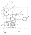
- Fig. 2 schematically shows the structure and the signal connection of a terminal 9 of the radio ripple control system 1 in the manner of a block diagram Fig. 1 in a first embodiment.
- the terminal 9 comprises a receiving device 17 for receiving a ripple control telegram 7, a processing device 19 for processing data transmitted with the ripple control telegram, a processing device downstream control signal output interface 21 for outputting a control signal obtained in the context of this processing and a display device 23 for displaying control signal Status information and other information for the user / operator.
- the display device 23 is designed as a touch-sensitive display screen (touchscreen) with a plurality of input fields 23i and at the same time serves as an input device for the manual input of data or control commands.
- the terminal 9 comprises a data memory 25 with a plurality of memory areas 25i and a program memory 27 with a plurality of memory areas 27i for storing a plurality of processing algorithms and also a measured value input 29 for connection to an external sensor or measuring device (not shown here).
- the input side of the processing device is preceded by a decryption unit 31 in which the content of a received encrypted ripple control telegram can be decrypted with a private key (which can be provided on another channel) via the combined display and input device 23.
- Fig. 3 shows in a further functional block diagram as a function modified and extended execution of a terminal 9 '. in this respect its components to those of the terminal 9 after Fig. 2 the same reference numbers have been used and these parts will not be reiterated here.
- a first essential difference is that the terminal 9 'of the decryption unit 31 is followed by an information separator 33, which is used to separate control information contained in the ripple control telegram 7 (telegram section 7.1) and additional information contained therein (telegram section 7.2) and for the separate forwarding of these serves both types of information. While the supplementary information is fed directly to the display unit 23 ', the control information reaches the processing device 19.
- the display device 23 is implemented exclusively as a display screen, and a separate input keyboard is used as the input device for control commands and data (including a code for the decryption unit 31) 35th
- the terminal device 9 ' has two measured value inputs 29.1, 29.2 for the input-side connection of two transducers, and the processing device 19' is configured correspondingly for the combined processing of two locally acquired measured variables in combination with the centrally provided control information in the ripple control telegram.
- the terminal 9 differs from the terminal 9 described above Fig. 2 by the additional provision of a consumer parameter memory 37 having a plurality of memory areas 37i in which data is stored for particular connected or connectable devices (consumers) that are relevant to their control in response to certain data transmitted by the ripple control telegram.
- a threshold value discriminator 39 provided in the processing unit 19 'enables, in particular, a threshold value discrimination of device-specific data stored in the consumer parameter memory 37 with current comparison values transmitted in the ripple control telegram and the derivation of control signals as a result of the threshold value processing.
- Another special feature of the terminal 9 ' is the presence of a reset input 41 in the processing unit 19, via which a resetting of the user / operator does not seem sensible output signal (control signal) or the processing leading to its output manually.
- Another specificity that makes sense in this connection is the provision of an alarm display area 43 on the display device 23, specifically for outputting alarm signals in the event of the provision of a "critical" control signal to be checked by the user / operator in the processing device 19 'serves.
- An associated display control area 45 in the processing device 19 ' serves to control this alarm display area 43.
Landscapes
- Engineering & Computer Science (AREA)
- Computer Networks & Wireless Communication (AREA)
- Physics & Mathematics (AREA)
- General Physics & Mathematics (AREA)
- Selective Calling Equipment (AREA)
Claims (17)
- Terminal (9; 9a-9c) d'un système de télécommande centralisée par radiodiffusion (1), comprenant un dispositif de réception (17),
un dispositif de traitement (19) pour le traitement combiné d'information reçue et d'information acquise localement sur le terminal ou saisie et/ou mémorisée dans le terminal, à savoir des valeurs de mesure et/ou des paramètres de consommateur,
une interface de sortie de signal de commande (21) pour la sortie d'un signal de commande généré par l'unité de traitement et
un dispositif d'affichage (23) relié au dispositif de réception et à l'unité de traitement pour l'affichage d'information reçue et d'un résultat de traitement avec l'information disponible localement, en particulier d'information se rapportant au signal de commande mis à disposition au niveau de l'interface de sortie de signal de commande, le dispositif de réception étant constitué pour de l'information gravée sur un support à ondes longues dans un télégramme de commande centralisée (7a-7c) selon la norme EFR. - Terminal selon la revendication 1, où, dans le dispositif de traitement (19), en particulier du côté de son entrée, un dispositif de séparation d'information (33) est prévu pour la séparation d'information de commande transmise par séquences de temps dans un télégramme de commande centralisée (7a-7c) et d'information de complément, le dispositif de séparation d'information (33) amenant l'information de commande à un traitement interne et au moins une partie de l'information de complément à l'unité d'affichage.
- Terminal selon la revendication 1 ou 2, où une unité de décodage (31) est assignée au dispositif de traitement (19), l'unité de décodage (31) étant assignée pour le décodage d'une information codée du côté émetteur, en particulier d'une information de complément, au moyen d'un code mémorisé en interne dans le terminal ou transmis dans un télégramme de données séparé et amené à l'unité de décodage via l'unité de réception.
- Terminal selon la revendication 3, où un dispositif de saisie de code (23) pour la saisie manuelle d'un code mis à disposition sur un canal séparé est assigné à l'unité de décodage (31).
- Terminal selon l'une des revendications précédentes, comprenant une unité de saisie (23 ; 35) qui est reliée à une mémoire de données et/ou de programmes de l'unité de traitement et/ou à une entrée du dispositif d'affichage, pour la saisie manuelle de données et/ou ordres de commande pertinents pour le traitement et/ou pertinents pour l'affichage.
- Terminal selon la revendication 4 et 5, où l'unité de saisie (23) reliée à une entrée de l'unité de traitement et/ou d'affichage (19 ; 23) sert en même temps d'unité de saisie du dispositif de décodage.
- Terminal selon la revendication 5 ou 6, où l'unité de saisie (23) est constituée par des champs de saisie (23i), lesquels sont formés dans le cadre d'un guidage d'utilisateur, d'un dispositif d'affichage (23) à écran tactile.
- Terminal selon l'une des revendications précédentes, où une mémoire de programmes (27) comprenant une pluralité de zones de mémoire de programmes (27i), lesquelles gardent en mémoire une pluralité d'algorithmes de traitement, en particulier de programmes de calcul de coûts, et une mémoire de données (25) comprenant une pluralité de zones de mémoire de données (25i), lesquelles gardent en mémoire en particulier au moins une pluralité de tarifs d'énergie, sont assignées au dispositif de traitement (19), au moins chacune des zones de mémoire de données étant adressable via un signal acquis à partir d'un télégramme de commande centralisée.
- Terminal selon l'une des revendications précédentes, où l'interface de sortie de signal de commande (21) est constituée pour la mise à disposition, en particulier en parallèle, de plusieurs signaux de commande indépendants les uns des autres, lesquels sont pourvus d'un codage pour la commande ciblée d'un consommateur raccordé ou raccordable déterminé.
- Terminal selon l'une des revendications précédentes, où une mémoire de paramètres de consommateur (37) pour la mise en mémoire de paramètres de raccordement et/ou de consommation d'au moins un consommateur raccordé ou raccordable est assigné à l'unité de traitement (19).
- Terminal selon la revendication 9 et 10, où la mémoire de paramètres de consommateur (37) présente une pluralité de zones de mémoire (37i) assignées à un consommateur respectivement, dans laquelle les paramètres de consommateur sont mémorisés en assignation à un codage de consommateur, lequel sert en même temps au codage d'un signal de commande sorti par l'unité de traitement pour le consommateur respectif.
- Terminal selon l'une des revendications 9 à 11, où une unité de commande d'affichage (45) pour la commande d'un affichage spécifique des signaux de commande codés pour différents consommateurs et facultativement de paramètres de consommateur associés et facultativement de résultats de traitement se rapportant au consommateur respectif est connectée en aval du dispositif de traitement (19).
- Terminal selon l'une des revendications 8 à 12, où le dispositif de traitement (19) présente au moins un discriminateur de valeur seuil (39) pour le traitement de valeur seuil d'un signal de tarif reçu dans un télégramme de commande centralisée avec une valeur seuil mémorisée dans une zone de mémoire de données interne pour la mise à disposition d'un signal de commande dépendant de la relation entre le signal de tarif et la valeur seuil au niveau de l'interface de sortie de signal de commande.
- Terminal selon la revendication 12 ou 13, où le dispositif d'affichage (23) présente une zone d'affichage d'alarme (43) reliée par signal au discriminateur de valeur seuil (39) pour la sortie d'un affichage d'alarme parallèlement à la mise à disposition d'un signal de commande provoquant la coupure d'un consommateur.
- Terminal selon la revendication 13 ou 14, où l'unité de traitement (19) présente une entrée de réinitialisation (41) reliée du côté de l'entrée à son unité de saisie, avec laquelle la sortie d'un signal de commande provoquant la coupure d'un consommateur peut être supprimée manuellement au niveau de l'interface de sortie de signal de commande (21).
- Terminal selon l'une des revendications précédentes, où le dispositif de traitement (19) présente une entrée de valeur de mesure (29.1, 29.2) pour la liaison avec au moins un capteur ou appareil de mesure local, en particulier une sonde de température (13a) et/ou un capteur d'éclairage (13b) et/ou un appareil de mesure de consommation d'énergie (15a, 15b), et pour l'intégration des valeurs de mesure acquises dans une opération de traitement.
- Terminal selon la revendication 16 et l'une des revendications 8 à 15, où plusieurs algorithmes de traitement qui spécifient un type déterminé de traitement de valeurs de mesure de plusieurs capteurs et/ou appareils de mesure raccordés sont mémorisés dans les zones de mémoire de programmes (27i), et où au moins une partie de ces zones de mémoire de programmes est adressable via un signal acquis à partir d'un télégramme de commande centralisée pour activer par commande centralisée un programme de traitement sélectionné.
Priority Applications (1)
| Application Number | Priority Date | Filing Date | Title |
|---|---|---|---|
| EP08103685A EP2112640B1 (fr) | 2008-04-23 | 2008-04-23 | Terminal d'un système de commande radio en continu |
Applications Claiming Priority (1)
| Application Number | Priority Date | Filing Date | Title |
|---|---|---|---|
| EP08103685A EP2112640B1 (fr) | 2008-04-23 | 2008-04-23 | Terminal d'un système de commande radio en continu |
Publications (2)
| Publication Number | Publication Date |
|---|---|
| EP2112640A1 EP2112640A1 (fr) | 2009-10-28 |
| EP2112640B1 true EP2112640B1 (fr) | 2012-10-03 |
Family
ID=39789315
Family Applications (1)
| Application Number | Title | Priority Date | Filing Date |
|---|---|---|---|
| EP08103685A Active EP2112640B1 (fr) | 2008-04-23 | 2008-04-23 | Terminal d'un système de commande radio en continu |
Country Status (1)
| Country | Link |
|---|---|
| EP (1) | EP2112640B1 (fr) |
Families Citing this family (3)
| Publication number | Priority date | Publication date | Assignee | Title |
|---|---|---|---|---|
| DE202010009128U1 (de) | 2010-06-16 | 2010-09-02 | Efr Europäische Funk-Rundsteuerung Gmbh | Anzeigegerät und Softwareprodukt zur Fern-Anzeige von Energieverbrauchsdaten |
| DE102010055565A1 (de) | 2010-12-23 | 2012-06-28 | Oszkár Szarvas | Signalempfangsbaustein |
| DE102020110649A1 (de) | 2020-04-20 | 2021-10-21 | SEK-Automobiltechnik GmbH | Verfahren und Vorrichtung Energieverbrauchs- und/oder Energieeinspeisesteuerung in einem elektrischen Energieversorgungsnetz |
Citations (1)
| Publication number | Priority date | Publication date | Assignee | Title |
|---|---|---|---|---|
| DE202006017739U1 (de) * | 2006-11-20 | 2007-02-22 | Hkw-Elektronik Gmbh | Einrichtung zum Empfang verschlüsselter Informationen |
Family Cites Families (4)
| Publication number | Priority date | Publication date | Assignee | Title |
|---|---|---|---|---|
| US6240365B1 (en) | 1997-01-21 | 2001-05-29 | Frank E. Bunn | Automated vehicle tracking and service provision system |
| US6720861B1 (en) * | 1999-03-12 | 2004-04-13 | Best Access Systems | Wireless security control system |
| DE10214146C1 (de) | 2002-03-28 | 2003-10-30 | Efr Europaeische Funk Rundsteu | Funk- Rundsteuerungssystem und Verfahren zum Betreiben eines derartigen Systems |
| FR2882599B1 (fr) * | 2005-02-25 | 2007-05-04 | Somfy Soc Par Actions Simplifi | Systeme de communication avec comptabilite croisee et trame de communication associee |
-
2008
- 2008-04-23 EP EP08103685A patent/EP2112640B1/fr active Active
Patent Citations (1)
| Publication number | Priority date | Publication date | Assignee | Title |
|---|---|---|---|---|
| DE202006017739U1 (de) * | 2006-11-20 | 2007-02-22 | Hkw-Elektronik Gmbh | Einrichtung zum Empfang verschlüsselter Informationen |
Also Published As
| Publication number | Publication date |
|---|---|
| EP2112640A1 (fr) | 2009-10-28 |
Similar Documents
| Publication | Publication Date | Title |
|---|---|---|
| EP0780252B1 (fr) | Equipement auxiliaire de véhicule activable avec une télécommande | |
| WO2014206543A1 (fr) | Procédé et dispositif de commande à distance d'une fonction d'un véhicule | |
| DE202007011806U1 (de) | Solarelementesystem mit Identchips | |
| DE102010001518A1 (de) | Vorrichtung zum Steuern von Betriebsfunktionen einer Werkzeugmaschine | |
| EP2112640B1 (fr) | Terminal d'un système de commande radio en continu | |
| DE102004007721A9 (de) | Schließ- und/oder Steuerungssystem, insbesondere für ein Kraftfahrzeug | |
| EP1479260B1 (fr) | Systeme de telecommande centralisee par radio et procede permettant de faire fonctionner un systeme de ce type | |
| DE102007042238A1 (de) | Alarmmelde- und Fernwirksystem zur Überwachung, Konfiguration und Fernbedienung von Geräten insbesondere in Nutzfahrzeugen und Immobilien | |
| DE102005011436A1 (de) | System zur Fernbedienung von Geräten und Komponenten in einem Fahrzeug, insbesondere Nutzfahrzeug | |
| DE69521776T2 (de) | Steuergerät zum Öffnen und Schliessen motorisierter Verdunklungsmittel, insbesondere Rolläden | |
| EP3528226B1 (fr) | Appareil de système destiné à fonctionner dans un réseau sans fil | |
| EP2299340A1 (fr) | Centrale, système et procédé de commande de dispositifs de fonctionnement dans des bâtiments | |
| CH712589B1 (de) | Überwachungsanordnung, Überwachungssystem und Verwendung einer Überwachungsanordnung zum Erfassen von Manipulationen an Hydranten. | |
| DE102004007681A1 (de) | Messvorrichtung zur frühzeitigen Erfassung eines Schadens an einem Maschinenteil | |
| DE10018373A1 (de) | Verfahren zur Fernbedienung von Geräten | |
| DE102004007679A1 (de) | Steuerungssystem für ein Kraftfahrzeug | |
| DE202009012554U1 (de) | Zentrale und System zur Steuerung von Funktionseinrichtungen in Gebäuden | |
| AT509746B1 (de) | Alarmanlage | |
| EP2189949A1 (fr) | Système de contrôle d'accès | |
| DE102008058660A1 (de) | Zutrittskontrollsystem | |
| EP3447746A1 (fr) | Dispositif de transmission de signal pour un dispositif, en particulier pour une caravane résidentielle, une caravane, une caravane automobile ou un bateau ainsi que système doté d'un tel dispositif de transmission de signal, et remorque et véhicule | |
| DE102022130914A1 (de) | Verfahren und System zur Steuerung einer Anlage | |
| EP2189950A1 (fr) | Système de contrôle d'accès | |
| DE20211318U1 (de) | Vorrichtung zum Anschluss von Stromquellen und elektrischen Verbrauchern in einem Wohnmobil oder Wohnwagen | |
| DE202014105746U1 (de) | Dämpfungsverstellsystem |
Legal Events
| Date | Code | Title | Description |
|---|---|---|---|
| PUAI | Public reference made under article 153(3) epc to a published international application that has entered the european phase |
Free format text: ORIGINAL CODE: 0009012 |
|
| AK | Designated contracting states |
Kind code of ref document: A1 Designated state(s): AT BE BG CH CY CZ DE DK EE ES FI FR GB GR HR HU IE IS IT LI LT LU LV MC MT NL NO PL PT RO SE SI SK TR |
|
| AX | Request for extension of the european patent |
Extension state: AL BA MK RS |
|
| 17P | Request for examination filed |
Effective date: 20100427 |
|
| AKX | Designation fees paid |
Designated state(s): AT BE BG CH CY CZ DE DK EE ES FI FR GB GR HR HU IE IS IT LI LT LU LV MC MT NL NO PL PT RO SE SI SK TR |
|
| 17Q | First examination report despatched |
Effective date: 20100616 |
|
| GRAP | Despatch of communication of intention to grant a patent |
Free format text: ORIGINAL CODE: EPIDOSNIGR1 |
|
| GRAS | Grant fee paid |
Free format text: ORIGINAL CODE: EPIDOSNIGR3 |
|
| GRAA | (expected) grant |
Free format text: ORIGINAL CODE: 0009210 |
|
| AK | Designated contracting states |
Kind code of ref document: B1 Designated state(s): AT BE BG CH CY CZ DE DK EE ES FI FR GB GR HR HU IE IS IT LI LT LU LV MC MT NL NO PL PT RO SE SI SK TR |
|
| REG | Reference to a national code |
Ref country code: GB Ref legal event code: FG4D Free format text: NOT ENGLISH |
|
| REG | Reference to a national code |
Ref country code: AT Ref legal event code: REF Ref document number: 578287 Country of ref document: AT Kind code of ref document: T Effective date: 20121015 Ref country code: CH Ref legal event code: EP |
|
| REG | Reference to a national code |
Ref country code: IE Ref legal event code: FG4D Free format text: LANGUAGE OF EP DOCUMENT: GERMAN |
|
| REG | Reference to a national code |
Ref country code: DE Ref legal event code: R096 Ref document number: 502008008294 Country of ref document: DE Effective date: 20121129 |
|
| PG25 | Lapsed in a contracting state [announced via postgrant information from national office to epo] |
Ref country code: SI Free format text: LAPSE BECAUSE OF FAILURE TO SUBMIT A TRANSLATION OF THE DESCRIPTION OR TO PAY THE FEE WITHIN THE PRESCRIBED TIME-LIMIT Effective date: 20121003 |
|
| REG | Reference to a national code |
Ref country code: NL Ref legal event code: VDEP Effective date: 20121003 |
|
| REG | Reference to a national code |
Ref country code: LT Ref legal event code: MG4D |
|
| PG25 | Lapsed in a contracting state [announced via postgrant information from national office to epo] |
Ref country code: LT Free format text: LAPSE BECAUSE OF FAILURE TO SUBMIT A TRANSLATION OF THE DESCRIPTION OR TO PAY THE FEE WITHIN THE PRESCRIBED TIME-LIMIT Effective date: 20121003 Ref country code: ES Free format text: LAPSE BECAUSE OF FAILURE TO SUBMIT A TRANSLATION OF THE DESCRIPTION OR TO PAY THE FEE WITHIN THE PRESCRIBED TIME-LIMIT Effective date: 20130114 Ref country code: SE Free format text: LAPSE BECAUSE OF FAILURE TO SUBMIT A TRANSLATION OF THE DESCRIPTION OR TO PAY THE FEE WITHIN THE PRESCRIBED TIME-LIMIT Effective date: 20121003 Ref country code: NL Free format text: LAPSE BECAUSE OF FAILURE TO SUBMIT A TRANSLATION OF THE DESCRIPTION OR TO PAY THE FEE WITHIN THE PRESCRIBED TIME-LIMIT Effective date: 20121003 Ref country code: FI Free format text: LAPSE BECAUSE OF FAILURE TO SUBMIT A TRANSLATION OF THE DESCRIPTION OR TO PAY THE FEE WITHIN THE PRESCRIBED TIME-LIMIT Effective date: 20121003 Ref country code: NO Free format text: LAPSE BECAUSE OF FAILURE TO SUBMIT A TRANSLATION OF THE DESCRIPTION OR TO PAY THE FEE WITHIN THE PRESCRIBED TIME-LIMIT Effective date: 20130103 Ref country code: HR Free format text: LAPSE BECAUSE OF FAILURE TO SUBMIT A TRANSLATION OF THE DESCRIPTION OR TO PAY THE FEE WITHIN THE PRESCRIBED TIME-LIMIT Effective date: 20121003 Ref country code: IS Free format text: LAPSE BECAUSE OF FAILURE TO SUBMIT A TRANSLATION OF THE DESCRIPTION OR TO PAY THE FEE WITHIN THE PRESCRIBED TIME-LIMIT Effective date: 20130203 |
|
| PG25 | Lapsed in a contracting state [announced via postgrant information from national office to epo] |
Ref country code: PL Free format text: LAPSE BECAUSE OF FAILURE TO SUBMIT A TRANSLATION OF THE DESCRIPTION OR TO PAY THE FEE WITHIN THE PRESCRIBED TIME-LIMIT Effective date: 20121003 Ref country code: LV Free format text: LAPSE BECAUSE OF FAILURE TO SUBMIT A TRANSLATION OF THE DESCRIPTION OR TO PAY THE FEE WITHIN THE PRESCRIBED TIME-LIMIT Effective date: 20121003 Ref country code: GR Free format text: LAPSE BECAUSE OF FAILURE TO SUBMIT A TRANSLATION OF THE DESCRIPTION OR TO PAY THE FEE WITHIN THE PRESCRIBED TIME-LIMIT Effective date: 20130104 Ref country code: PT Free format text: LAPSE BECAUSE OF FAILURE TO SUBMIT A TRANSLATION OF THE DESCRIPTION OR TO PAY THE FEE WITHIN THE PRESCRIBED TIME-LIMIT Effective date: 20130204 Ref country code: CY Free format text: LAPSE BECAUSE OF FAILURE TO SUBMIT A TRANSLATION OF THE DESCRIPTION OR TO PAY THE FEE WITHIN THE PRESCRIBED TIME-LIMIT Effective date: 20121003 |
|
| PG25 | Lapsed in a contracting state [announced via postgrant information from national office to epo] |
Ref country code: DK Free format text: LAPSE BECAUSE OF FAILURE TO SUBMIT A TRANSLATION OF THE DESCRIPTION OR TO PAY THE FEE WITHIN THE PRESCRIBED TIME-LIMIT Effective date: 20121003 Ref country code: SK Free format text: LAPSE BECAUSE OF FAILURE TO SUBMIT A TRANSLATION OF THE DESCRIPTION OR TO PAY THE FEE WITHIN THE PRESCRIBED TIME-LIMIT Effective date: 20121003 Ref country code: CZ Free format text: LAPSE BECAUSE OF FAILURE TO SUBMIT A TRANSLATION OF THE DESCRIPTION OR TO PAY THE FEE WITHIN THE PRESCRIBED TIME-LIMIT Effective date: 20121003 Ref country code: BG Free format text: LAPSE BECAUSE OF FAILURE TO SUBMIT A TRANSLATION OF THE DESCRIPTION OR TO PAY THE FEE WITHIN THE PRESCRIBED TIME-LIMIT Effective date: 20130103 Ref country code: EE Free format text: LAPSE BECAUSE OF FAILURE TO SUBMIT A TRANSLATION OF THE DESCRIPTION OR TO PAY THE FEE WITHIN THE PRESCRIBED TIME-LIMIT Effective date: 20121003 |
|
| PGFP | Annual fee paid to national office [announced via postgrant information from national office to epo] |
Ref country code: GB Payment date: 20130429 Year of fee payment: 6 |
|
| PLBE | No opposition filed within time limit |
Free format text: ORIGINAL CODE: 0009261 |
|
| STAA | Information on the status of an ep patent application or granted ep patent |
Free format text: STATUS: NO OPPOSITION FILED WITHIN TIME LIMIT |
|
| PG25 | Lapsed in a contracting state [announced via postgrant information from national office to epo] |
Ref country code: IT Free format text: LAPSE BECAUSE OF FAILURE TO SUBMIT A TRANSLATION OF THE DESCRIPTION OR TO PAY THE FEE WITHIN THE PRESCRIBED TIME-LIMIT Effective date: 20121003 Ref country code: RO Free format text: LAPSE BECAUSE OF FAILURE TO SUBMIT A TRANSLATION OF THE DESCRIPTION OR TO PAY THE FEE WITHIN THE PRESCRIBED TIME-LIMIT Effective date: 20121003 |
|
| PGFP | Annual fee paid to national office [announced via postgrant information from national office to epo] |
Ref country code: TR Payment date: 20130401 Year of fee payment: 6 Ref country code: FR Payment date: 20130529 Year of fee payment: 6 |
|
| 26N | No opposition filed |
Effective date: 20130704 |
|
| BERE | Be: lapsed |
Owner name: EFR EUROPAISCHE FUNK-RUNDSTEUERUNG Effective date: 20130430 |
|
| REG | Reference to a national code |
Ref country code: DE Ref legal event code: R097 Ref document number: 502008008294 Country of ref document: DE Effective date: 20130704 |
|
| PG25 | Lapsed in a contracting state [announced via postgrant information from national office to epo] |
Ref country code: MC Free format text: LAPSE BECAUSE OF FAILURE TO SUBMIT A TRANSLATION OF THE DESCRIPTION OR TO PAY THE FEE WITHIN THE PRESCRIBED TIME-LIMIT Effective date: 20121003 |
|
| REG | Reference to a national code |
Ref country code: CH Ref legal event code: PL |
|
| REG | Reference to a national code |
Ref country code: IE Ref legal event code: MM4A |
|
| PG25 | Lapsed in a contracting state [announced via postgrant information from national office to epo] |
Ref country code: LI Free format text: LAPSE BECAUSE OF NON-PAYMENT OF DUE FEES Effective date: 20130430 Ref country code: BE Free format text: LAPSE BECAUSE OF NON-PAYMENT OF DUE FEES Effective date: 20130430 Ref country code: CH Free format text: LAPSE BECAUSE OF NON-PAYMENT OF DUE FEES Effective date: 20130430 |
|
| PG25 | Lapsed in a contracting state [announced via postgrant information from national office to epo] |
Ref country code: IE Free format text: LAPSE BECAUSE OF NON-PAYMENT OF DUE FEES Effective date: 20130423 |
|
| REG | Reference to a national code |
Ref country code: AT Ref legal event code: MM01 Ref document number: 578287 Country of ref document: AT Kind code of ref document: T Effective date: 20130423 |
|
| PG25 | Lapsed in a contracting state [announced via postgrant information from national office to epo] |
Ref country code: AT Free format text: LAPSE BECAUSE OF NON-PAYMENT OF DUE FEES Effective date: 20130423 |
|
| GBPC | Gb: european patent ceased through non-payment of renewal fee |
Effective date: 20140423 |
|
| REG | Reference to a national code |
Ref country code: FR Ref legal event code: ST Effective date: 20141231 |
|
| PG25 | Lapsed in a contracting state [announced via postgrant information from national office to epo] |
Ref country code: GB Free format text: LAPSE BECAUSE OF NON-PAYMENT OF DUE FEES Effective date: 20140423 |
|
| PG25 | Lapsed in a contracting state [announced via postgrant information from national office to epo] |
Ref country code: MT Free format text: LAPSE BECAUSE OF FAILURE TO SUBMIT A TRANSLATION OF THE DESCRIPTION OR TO PAY THE FEE WITHIN THE PRESCRIBED TIME-LIMIT Effective date: 20121003 Ref country code: FR Free format text: LAPSE BECAUSE OF NON-PAYMENT OF DUE FEES Effective date: 20140430 |
|
| PG25 | Lapsed in a contracting state [announced via postgrant information from national office to epo] |
Ref country code: HU Free format text: LAPSE BECAUSE OF FAILURE TO SUBMIT A TRANSLATION OF THE DESCRIPTION OR TO PAY THE FEE WITHIN THE PRESCRIBED TIME-LIMIT; INVALID AB INITIO Effective date: 20080423 Ref country code: LU Free format text: LAPSE BECAUSE OF NON-PAYMENT OF DUE FEES Effective date: 20130423 |
|
| PG25 | Lapsed in a contracting state [announced via postgrant information from national office to epo] |
Ref country code: TR Free format text: LAPSE BECAUSE OF NON-PAYMENT OF DUE FEES Effective date: 20140423 |
|
| P01 | Opt-out of the competence of the unified patent court (upc) registered |
Effective date: 20230601 |
|
| PGFP | Annual fee paid to national office [announced via postgrant information from national office to epo] |
Ref country code: DE Payment date: 20250430 Year of fee payment: 18 |