EP2112681A2 - Système de spectromètre de masse - Google Patents
Système de spectromètre de masse Download PDFInfo
- Publication number
- EP2112681A2 EP2112681A2 EP09153241A EP09153241A EP2112681A2 EP 2112681 A2 EP2112681 A2 EP 2112681A2 EP 09153241 A EP09153241 A EP 09153241A EP 09153241 A EP09153241 A EP 09153241A EP 2112681 A2 EP2112681 A2 EP 2112681A2
- Authority
- EP
- European Patent Office
- Prior art keywords
- nozzle
- vacuum chamber
- ions
- interface component
- mass analyser
- Prior art date
- Legal status (The legal status is an assumption and is not a legal conclusion. Google has not performed a legal analysis and makes no representation as to the accuracy of the status listed.)
- Granted
Links
Images





Classifications
-
- H—ELECTRICITY
- H01—ELECTRIC ELEMENTS
- H01J—ELECTRIC DISCHARGE TUBES OR DISCHARGE LAMPS
- H01J49/00—Particle spectrometers or separator tubes
- H01J49/26—Mass spectrometers or separator tubes
-
- H—ELECTRICITY
- H01—ELECTRIC ELEMENTS
- H01J—ELECTRIC DISCHARGE TUBES OR DISCHARGE LAMPS
- H01J9/00—Apparatus or processes specially adapted for the manufacture, installation, removal, maintenance of electric discharge tubes, discharge lamps, or parts thereof; Recovery of material from discharge tubes or lamps
-
- H—ELECTRICITY
- H01—ELECTRIC ELEMENTS
- H01J—ELECTRIC DISCHARGE TUBES OR DISCHARGE LAMPS
- H01J49/00—Particle spectrometers or separator tubes
- H01J49/02—Details
- H01J49/04—Arrangements for introducing or extracting samples to be analysed, e.g. vacuum locks; Arrangements for external adjustment of electron- or ion-optical components
- H01J49/0404—Capillaries used for transferring samples or ions
-
- H—ELECTRICITY
- H01—ELECTRIC ELEMENTS
- H01J—ELECTRIC DISCHARGE TUBES OR DISCHARGE LAMPS
- H01J49/00—Particle spectrometers or separator tubes
- H01J49/02—Details
- H01J49/04—Arrangements for introducing or extracting samples to be analysed, e.g. vacuum locks; Arrangements for external adjustment of electron- or ion-optical components
-
- B—PERFORMING OPERATIONS; TRANSPORTING
- B33—ADDITIVE MANUFACTURING TECHNOLOGY
- B33Y—ADDITIVE MANUFACTURING, i.e. MANUFACTURING OF THREE-DIMENSIONAL [3D] OBJECTS BY ADDITIVE DEPOSITION, ADDITIVE AGGLOMERATION OR ADDITIVE LAYERING, e.g. BY 3D PRINTING, STEREOLITHOGRAPHY OR SELECTIVE LASER SINTERING
- B33Y80/00—Products made by additive manufacturing
-
- Y—GENERAL TAGGING OF NEW TECHNOLOGICAL DEVELOPMENTS; GENERAL TAGGING OF CROSS-SECTIONAL TECHNOLOGIES SPANNING OVER SEVERAL SECTIONS OF THE IPC; TECHNICAL SUBJECTS COVERED BY FORMER USPC CROSS-REFERENCE ART COLLECTIONS [XRACs] AND DIGESTS
- Y10—TECHNICAL SUBJECTS COVERED BY FORMER USPC
- Y10T—TECHNICAL SUBJECTS COVERED BY FORMER US CLASSIFICATION
- Y10T29/00—Metal working
- Y10T29/49—Method of mechanical manufacture
Definitions
- the invention relates to components for use with a mass spectrometer system.
- the invention provides for an interface component that in various configurations acts as a means to transfer a beam of ions from one location to another.
- the interface may be used to transfer, guide, direct or collimate a beam of ions of interest from an ion source into a mass spectrometer detector or mass analyser for analysis by their mass to charge ratio.
- This interface component may be used as a vacuum interface for an atmospheric pressure ionisation (API) mass spectrometer (MS) system.
- API atmospheric pressure ionisation
- MS mass spectrometer
- Such an interface component desirably comprises a nozzle having a diverging portion providing for acceleration of the ions as they pass through.
- the nozzle may be configured to have only a diverging portion or may also a converging portion.
- Such an arrangement known as a a de Laval, or converging-diverging, nozzle is described for use as a vacuum interface to transfer a beam of ions from an atmospheric pressure ionisation source into a vacuum chamber for analysis by a mass spectrometer in an API-MS system.
- Mass spectrometry is a powerful analytical technique that is used for the qualitative and quantitative identification of organic molecules, peptides, proteins and nucleic acids. MS offers speed, accuracy and high sensitivity.
- Key components of a mass spectrometer are the ion source, ion coupling optics, mass analyser and detector.
- the ion source transforms analyte molecules into a stream of charged particles, or ions, through a process of electron addition or subtraction.
- the ions can be 'steered' using electric or magnetic fields.
- Ion coupling optics or lenses collimate the ion flux from the ion source into the mass analyser. The analyser separates ions by their mass to charge ratio.
- mass analyser Several different kinds of mass analyser are known in the art, including, but not limited to; magnetic sector, quadrupole, ion trap, time of flight and cycloidal.
- the ions exit the analyser in order of mass to charge ratio and in so doing produces a mass spectrum which is a unique signature or 'fingerprint' for the analyte.
- Ions are directed to a detector where they impact and discharge an ion current which may be counted and amplified by signal electronics before being displayed on a computer screen as a mass spectrum.
- the detector is normally an electron multiplier.
- These components together form the analytical sub-systems of the mass spectrometer system.
- Other mass spectrometer system components include vacuum pumps, a vacuum chamber, drive electronics, data acquisition electronics, power supplies and enclosures.
- API techniques include, but are not limited to, electrospray ionisation (ESI), nanospray ionisation, atmospheric pressure chemical ionisation (APCI), desorption electrospray ionisation (DESI), atmospheric pressure glow discharge ionisation (APGDI) or direct analysis in real-time (DART).
- ESI electrospray ionisation
- APCI atmospheric pressure chemical ionisation
- DESI desorption electrospray ionisation
- APIGDI atmospheric pressure glow discharge ionisation
- DART direct analysis in real-time
- a vacuum interface To transfer ions generated at atmospheric pressure inside the vacuum chamber a vacuum interface is required.
- the function of a vacuum interface is to provide a means of allowing ions generated at atmospheric pressure to be passed into a high-vacuum system for analysis by a mass spectrometer.
- the vacuum interface ensures that the ions preferentially travel in a forward direction, so that they can be efficiently passed into a mass spectrometer for analysis.
- the vacuum interface should also use orifices of sufficient size that they do not easily clog, but at the same time match the flow rates of ions, and the much larger associated flow of neutrals, to the pumping speed of the vacuum pumps to ensure that a vacuum is maintained in order for the mass spectrometer to operate effectively.
- the ideal vacuum interface also enhances the transmission of ions compared with neutrals, or increases the concentration of ions relative to neutrals.
- an interface between an atmospheric pressure ionisation source and a mass spectrometer system comprising a diverging portion which serves to allow for acceleration of a beam of ions as they are transferred into a mass spectrometer for analysis.
- the nozzle may also comprises a converging portion, such as provided by a de Laval nozzle, also known as a converging-diverging or 'con-di' nozzle
- a de Laval nozzle also known as a converging-diverging or 'con-di' nozzle
- the de Laval nozzle takes advantage of the counter-intuitive behaviour of compressible flow.
- incompressible flow i.e. flow of a liquid
- compressible flow i.e. flow of a gas
- this increase can only be maintained up to Mach 1, the speed of sound.
- Mach 1 Once Mach 1 has been reached, decreasing the channel cross-section any further makes no difference.
- a further increase in flow velocity can only be obtained if the channel cross-section is increased.
- the increase in velocity is obtained in a constant entropy process by cooling the molecules, so that their thermal energy is traded for an increase in kinetic energy in the desired axial direction.
- the pressure drops.
- the expected improvement in useful centreline flux over an effusive source is ⁇ M 2 /2 + 3/2, where ⁇ is the ratio of the specific heats and M is the Mach number. Since ⁇ is of about 1, and M is typically > 20 in a well designed jet expansion system, the improvement could be very significant (i.e. several hundred-fold).
- a de Laval nozzle acts as an interface between an atmospheric pressure ionisation source and a mass spectrometer inside a vacuum vessel.
- the de Laval nozzle transfers ions from the API directly to the vacuum chamber should result in the desired axial flow into the mass spectrometer.
- the flow in the converging section of the nozzle is very similar to the local flow at the input to a simple orifice, but the diverging section directs and accelerates the flow. Consequently, by use of a nozzle having a portion of which defines a diverging inner path, such as that provided by a de Laval nozzle, it is possible to improve the useful ion flux very considerably.
- a de Laval nozzle used as a single stage interface between atmospheric pressure and the vacuum chamber desirably should be provided having the same limiting aperture size or throat size as a simple orifice.
- clogging of the nozzle could arise.
- This however has a disadvantage of needing larger pumps to maintain vacuum.
- the solution to the problem of very small apertures is to use a two-stage, or multi-stage, system.
- the expansion of the gas is only carried out to an intermediate pressure.
- a much larger input orifice can now be used, because pumps operating at intermediate pressure can have much higher pumping rates than a vacuum pump such as a turbo at the same pressure. They can also start pumping at atmosphere, a necessity for practical operation.
- the excess flux of molecules is simply pumped away before it reaches the second, low vacuum chamber.
- a second orifice between the first intermediate vacuum chamber and the second main vacuum chamber transfers a stream of ions and neutrals into the main vacuum chamber.
- a de Laval nozzle or alternatively a diverging only nozzle may be substituted for either the input orifice or the second orifice, or for both.
- a combination of nozzles may be used as an interface between one or more of the vacuum chambers held at different pressures. The specific configuration for each of these plurality of nozzles where used will depend on the specifics of the interface required. It will however be appreciated that where further expansion is required a diverging nozzle only is a desirable option.
- a DC or AC ion guide could be used after the nozzle to efficiently transfer the ions to mass analyser for analysis.
- the ion guide increases the concentration of ions by trapping and focusing the ions in the stream while at the same time pumping away neutrals.
- the ion beam may be focussed by means of an electrostatic or electrodynamic field between the electrodes of the ion guide.
- a pseudopotential well is created between the electrodes by the changing electrical field. The pseudopotential well focuses and collimates the ion beam down the axis of the ion guide.
- collisional focussing may be induced to further focus the ion beam.
- the pre-filter of a quadrupole mass analyser is used as an ion guide by simply lengthening it so that it captures the supersonic stream of ions and neutrals as it exits from the diverging section of the nozzle.
- the pre-filter or ion guide is positioned so that the leading edges of the rods are placed either inside or outside the diverging section of the nozzle such that the pre-filter rods capture or intercept the supersonic stream of ions exiting the nozzle. The field generated between the pre-filter rods then traps and guides the ions.
- the pre-filter or ion guide would continue for a length such that the neutrals were likely to be pumped away, and would trap and focus ions within the pseudopotential field of the ion guide so that only ions were left by the time they reached the mass analyser.
- the nozzle may be fabricated using a process capable of generating the dimensions and tolerances required to create the ideal diverging section and if providing a converging portion as well then the process will also desirably generate the dimensions and profiles of an ideal converging section and throat portion.
- the throat diameter should be small enough to maintain vacuum (e.g. throat diameter - 50 um) inside the vacuum chamber, but with the correct converging-diverging nozzle profile necessary to collimate and accelerate a beam of ions and neutrals to supersonic velocities.
- the converging portion should precede the throat portion which should precede the diverging portion.
- Some possible techniques for fabricating such a nozzle include:
- the nozzle may be a hybrid device based on machined converging and diverging sections coupled with a micro-engineered throat section.
- part of the nozzle for example the throat, could be fabricated and attached to a larger, conventionally machined (or turned, or EDM machined, or injection moulded or micromachined, or electroformed) diverging nozzle part with the correct geometry to further accelerate and focus ions and neutral gas molecules into the mass analyser.
- the advantage of a hybrid device is that the diverging section could have the larger dimensions and geometry necessary to promote acceleration to higher mach numbers.
- the cheaper, micromachined part could be disposable, with machined, metal part being fixed.
- Another configuration for such a hybrid approach is to fabricate a hybrid nozzle by etching the narrower throat section from a semiconductor material and to attach this micromachined part to a conventionally turned, or EDM-fabricated, longer diverging nozzle part. Again, the micromachined part would be disposed of when clogged.
- Figure 1A is a diagram of the classic de Laval nozzle with a converging section, a throat and a diverging section.
- the purpose of the converging section is to achieve flow of Mach 1 at the throat. Downstream at the exit to the diverging section axial flow is accelerated to supersonic velocities, and the flow is largely collimated around the centreline of the nozzle.
- Figure 1B is an example of a nozzle without the converging section that was evident in Figure 1A .
- Such an embodiment provides a diverging portion and could be substituted for the classic case shown in Figure 1A in any of the embodiments disclosed herein.
- FIG. 2 shows the mass spectrometer system of the invention wherein a de Laval nozzle is used as a vacuum interface to transfer ions between an atmospheric pressure ionisation (API) source and a mass analyser.
- API atmospheric pressure ionisation
- Typical API techniques include, but are not limited to, electrospray ionisation (ESI), nanospray ionisation, atmospheric pressure chemical ionisation (APCI), desorption electrospray ionisation (DESI), atmospheric pressure glow discharge ionisation (APGDI) or direct analysis in real-time (DART).
- the nozzle 306 of the mass spectrometer system of the invention acts as an interface between an atmospheric pressure ionisation (API) source 304 and a mass analyser 301, and produces a well-collimated, supersonic beam of ions and neutrals 307 at the exit of its diverging section which is located inside the vacuum chamber 302.
- the vacuum chamber is maintained at a pressure suitable for operation of the mass analyser by vacuum pumps 303.
- This focused, supersonic beam 307 is presented to a mass analyser 301 where the ions are analysed by their mass to charge ratios.
- the mass analyser may be a quadrupole, ion trap, time of flight, 'orbitrap', magnetic sector, Fourier transform, cycloidal MS or some other mass analyser.
- ions and neutrals are pumped away into the first pump 406A, the remaining particles are transferred into the second chamber via the nozzle 407A, finally entering a second, high vacuum chamber as a well-collimated, supersonic beam of ions and neutrals 408A which are then analysed by a mass analyser 409A.
- the second vacuum chamber 411A is maintained at a lower pressure than the first chamber by a vacuum pump, or pumps 405A.
- Pump 405A is preferable a turbomolecular pump.
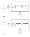
- Figure 4B is the mass spectrometer system of the invention with two vacuum chambers as in Figure 4A , but with the first, simple orifice replaced with the nozzle of the invention.
- Ions are generated at the API source 401B and are transported, accelerated and collimated into a supersonic stream 404B along with atmospheric neutrals by a nozzle 403B into a first region 410B at intermediate pressure.
- Some fraction of the ions and neutrals are pumped away, the remaining portion are again transported, accelerated and collimated by a second nozzle 407B into a supersonic beam 408B into a second chamber 411B held at a lower pressure where they are presented to a mass analyser 409B.
- the remaining ions are analysed by their mass to charge ratios in the mass analyser.
- FIG. 5 is a schematic of one embodiment of the mass spectrometer system of the invention which features a single vacuum chamber 508 housing a mass analyser 506 and an ion guide 505.
- the vacuum chamber 508 communicates with an atmospheric pressure ionisation source 501 via a nozzle 503.
- Ions and neutrals moving randomly 502 are coupled into a nozzle 503.
- the nozzle 503 generates a supersonic beam of ions and neutrals 504 at the exit to its diverging section. This beam is collimated so it may be readily intercepted by, or received into, an ion guide 505.
- the function of the ion guide 505 is to enrich the ion beam by trapping and conveying ions inside an electrical or magnetic field while allowing neutrals to be pumped away by the pumps of the vacuum system 509.
- the beam 507 exiting this ion guide should have a lower proportion of neutral particles, and a higher proportion of ions.
- This ion beam 507 is presented to a mass analyser 506 for analysis.
- the ion guide 505 may be a DC or AC field generated by some arrangement of electrodes. Various arrays of electrodes, or various arrangements of electrode geometries, may be used to create a trapping and focussing field.
- Ion guides known in the art include quadrupoles, hexapoles, octopoles, stacked-ring ion guides, or a series of diaphragm electrodes.
- Figure 6 is another embodiment of the mass spectrometer system of the invention featuring a single vacuum chamber 608 housing a mass analyser 607 and an ion guide 605.
- the vacuum chamber 608 communicates with an atmospheric pressure ionisation source 601 via a nozzle 603.
- the nozzle 603 generates a supersonic beam of ions and neutrals 604 at the exit to its diverging section. This beam is collimated, and can therefore can be intercepted by, or received into, an ion guide 605.
- the ion guide 605 is a quadrupole ion guide
- the mass analyser is a quadrupole mass analyser 607.
- the quadrupole ion guide 605 efficiently intercepts or captures the collimated beam of ions and neutrals 604 exiting the diverging section of the nozzle 603 at supersonic velocities.
- the neutral gas molecules are gradually pumped away by the pumps 609 in the ion guide 605, leaving a concentrated beam of ions 606 which is conveyed to a quadrupole mass analyser 607.
- the ion guide 704 may be a RF device such as a quadrupole, hexapole, octapole or a stack of ring electrodes, or annular or planar DC focussing electrodes.
- the ion guide 704 retains ions while allowing neutrals to be pumped away 710.
- the ions exit the ion guide 705 and enter a nozzle 706, where they are accelerated along with remaining neutrals into a second chamber.
- the ions exit the nozzle supersonically 707, and are received by a mass analyser 708.
- ion enrichment may be achieved by applying a DC bias to second nozzle 706, ions may be draw into its converging section, or concentrated down the centreline of nozzle 706 by repelling them from its surfaces.
- Figure 8 is an embodiment of a two-chamber mass spectrometer system consisting of an API source 801 communicating with a first, intermediate pressure, chamber 806 via a first nozzle 812, and a second, high vacuum, chamber 810 communicating with the first 806 via a second nozzle 813.
- the first chamber contains an ion guide 804.
- the second chamber communicates with the first chamber, and the ion guide 804 of the first chamber, via a nozzle 813.
- the API source 801 generates ions 802 outside the vacuum system. A mixture of ions and neutrals 802 is transferred into the first vacuum chamber 806 via the first nozzle 812. These ions and neutrals exit the nozzle supersonically, and enter an ion guide 804.
- the ion guide 804 may be a RF device such as a quadrupole, hexapole, octapole or a stack of ring electrodes, or annular or planar DC focussing electrodes.
- the ion guide retains ions while allowing neutrals to be pumped away 807.
- the ions exit the ion guide 805 and enter a second nozzle 813, where they are again accelerated 808 along with remaining neutrals into a second chamber 810.
- the ions exit the nozzle supersonically 808, and are received by a mass analyser 809.
- Figure 9A is a diagram of an embodiment of a two-chamber mass spectrometer system with an API source 901A communicating with a first vacuum chamber 907A via a simple orifice 904A.
- the first chamber 907A is held at a pressure intermediate between the pressure of the second chamber and atmospheric pressure.
- the first chamber 907A contains an ion guide 905A, which is preferably a quadrupole operated in RF mode as an ion conveyor or ion transporter. Ions and neutrals enter the first chamber effusively 903A. Some portion of this effusive mixture is intercepted by the RF ion guide 905A. Ions are retained while neutral gas molecules are gradually pumped away by the vacuum system 908A.
- Ions 906A exit the ion guide 905A through a second nozzle 909A where they are accelerated and collimated into the second chamber 912A as a beam 910A.
- the second chamber 912A is held at a lower, high vacuum, pressure by the vacuum system 913A.
- This beam of ions and remaining neutrals 910A is intercepted, captured or received by a mass analyser 911A, preferably a quadrupole mass spectrometer.
- the ions are analysed by the quadrupole MS 911A in the high vacuum chamber 912A.
- Figure 9B is another embodiment of the mass spectrometer system of the invention featuring an API source 901B and two vacuum chambers 911 B and 910B wherein ions and neutrals 902B are transported into the first, intermediate pressure chamber 911B via a first nozzle 903B rather than a simple orifice. Ions and neutral gas molecules exit the diverging section of the first nozzle as supersonic beam 904B. Since this beam 904B is collimated, it can be intercepted, captured or received by a RF ion guide 905B located at the exit of the first nozzle 903B, inside the intermediate pressure chamber 911B.
- Ions are trapped and guided down the centreline of the RF ion guide 905B, preferably a RF quadrupole, while neutral gas molecules are gradually pumped away by the vacuum system.
- a second nozzle 907B At the exit of the ion guide 905B there is a higher concentration of ions to neutrals 906B.
- These ions and remaining neutrals are transferred to the second, high vacuum chamber 910B via a second nozzle 907B.
- This nozzle 907B generates a well-collimated supersonic beam 908B which exits the diverging section of the second nozzle inside the high vacuum chamber.
- This beam is intercepted 908B or received by a mass analyser 909B, preferably in this embodiment a quadrupole mass spectrometer.
- the ions are analysed by their charge to mass ratios, generating a mass spectrum at a Channeltron or multiplying detector situated at the exit of the quadrupole mass spectrometer 909B.
- Figure 10 is a schematic of the classic de Laval, or converging-diverging, nozzle.
- the nozzle profile may be created through fabrication of one or more sections which may be subsequently assembled. This hybrid approach may be particularly useful when it is impossible to obtain the necessary tolerances and dimensions required along the profile from one manufacturing process. For illustration, 3 sections are shown in figure 10 .
- sections 10A, 10B and 10C can fabricated separately using the combinations of the processes and materials represented by the hatched regions in Table 1. Those hatched regions on table 1 represents preferred machining techniques for the materials listed.
- the materials are composite materials (including conductive polymers), polymer, polyimide, Su8, semiconductor materials, glass, Pyrex and ceramic and diamond.
- the processes listed are micro-injection moulding, Excimer laser machining, electroforming, crystal plane etching, wet etching, LIGA, Deep Reactive Ion Etching, Reactive Ion Etching, Electrical Discharge Machining, Stereo-lithography, laser machining, ultrasonic polishing and metal wire draw through polishing. Sections 10A, 10B and 10C fabricated using some combination of these processes and materials may be subsequently assembled together to form the nozzle vacuum interface for use in an API-MS.
- Figure 10 shows the arrangement of a de Laval nozzle delineated into three distinct regions: a converging portion 10A, a throat portion 10B and a diverging portion 10C. It will be appreciated from an inspection of Figure 3 that the separation between side walls in the converging and diverging portions is much greater than that in the throat portion. The proximity of the majority of the ions passing through this centre region to the side walls is much greater than the proximity of the majority of the ions to the side walls of the converging and diverging regions.
- Such a hard material allows for the surface treatment of the side walls of the region fabricated from that hard material to provide a highly polished surface.
- This surface treatment could, in an exemplary arrangement, be provided by using ultrasonic polishing and/or by drawing and rotating a metal wire through the centre region with a suitable polishing compound.
- the side walls of this centre region are fabricated from a material so as to provide a hard surface for subsequent polishing, it is possible to form the side walls separate to the body of the region.
- a preferred arrangement however is to fabricate the entire region from the same material. By providing a block of such a hard material, one or more lasers could be used to create the accurate internal diverging profile and throat in this very hard material. If required on the opposite side, a converging profile would be added. The full internal profiles would be machined into the remaining parts made from metal or similar easily machinable material to create the assembled nozzle shape.
Landscapes
- Chemical & Material Sciences (AREA)
- Analytical Chemistry (AREA)
- Engineering & Computer Science (AREA)
- Manufacturing & Machinery (AREA)
- Other Investigation Or Analysis Of Materials By Electrical Means (AREA)
- Electron Tubes For Measurement (AREA)
- Analysing Materials By The Use Of Radiation (AREA)
Applications Claiming Priority (1)
| Application Number | Priority Date | Filing Date | Title |
|---|---|---|---|
| GB0803256A GB2457708B (en) | 2008-02-22 | 2008-02-22 | Mass spectrometer system |
Publications (3)
| Publication Number | Publication Date |
|---|---|
| EP2112681A2 true EP2112681A2 (fr) | 2009-10-28 |
| EP2112681A3 EP2112681A3 (fr) | 2010-12-29 |
| EP2112681B1 EP2112681B1 (fr) | 2015-04-08 |
Family
ID=39284386
Family Applications (1)
| Application Number | Title | Priority Date | Filing Date |
|---|---|---|---|
| EP20090153241 Active EP2112681B1 (fr) | 2008-02-22 | 2009-02-19 | Système de spectromètre de masse |
Country Status (5)
| Country | Link |
|---|---|
| US (1) | US8269164B2 (fr) |
| EP (1) | EP2112681B1 (fr) |
| JP (1) | JP5443019B2 (fr) |
| CA (1) | CA2654659A1 (fr) |
| GB (1) | GB2457708B (fr) |
Cited By (3)
| Publication number | Priority date | Publication date | Assignee | Title |
|---|---|---|---|---|
| GB2470287A (en) * | 2009-05-13 | 2010-11-17 | Micromass Ltd | Diamond like carbon coating on surface of a sampling cone of a mass spectrometer |
| WO2011061147A1 (fr) * | 2009-11-17 | 2011-05-26 | Bruker Daltonik Gmbh | Utilisation des écoulements de gaz dans des spectromètres de masse |
| JP2016018625A (ja) * | 2014-07-07 | 2016-02-01 | 株式会社日立ハイテクノロジーズ | 質量分析装置 |
Families Citing this family (26)
| Publication number | Priority date | Publication date | Assignee | Title |
|---|---|---|---|---|
| DE102008051695B4 (de) * | 2008-09-04 | 2019-06-06 | Bruker Daltonik Gmbh | Ionenmobilitätsmessung an Potentialbarriere |
| JP5364468B2 (ja) * | 2008-09-26 | 2013-12-11 | 日精樹脂工業株式会社 | めっき被覆アルミニウム製品 |
| JP5359827B2 (ja) * | 2008-12-03 | 2013-12-04 | 株式会社島津製作所 | イオン輸送装置、イオン分析装置、及び、超音速分子ジェット法を用いた分析装置 |
| US8471198B2 (en) | 2009-05-13 | 2013-06-25 | Micromass Uk Limited | Mass spectrometer sampling cone with coating |
| DE102009050040B4 (de) | 2009-08-28 | 2014-10-30 | Bruker Daltonik Gmbh | Einlass von Ionen in Massenspektrometer durch Lavaldüsen |
| DE102009050041B4 (de) * | 2009-09-17 | 2014-12-18 | Bruker Daltonik Gmbh | Hochauflösende Ionenmobiltätsspektrometrie |
| US8058611B2 (en) * | 2009-09-23 | 2011-11-15 | Thermo Finnigan Llc | System for preventing backflow in an ion source |
| GB2474293B (en) | 2009-10-12 | 2012-12-26 | Microsaic Systems Plc | Portable analytical system for on-site analysis of fluids |
| GB2475742B (en) * | 2009-11-30 | 2014-02-12 | Microsaic Systems Plc | Sample collection and detection system |
| GB2479191B (en) | 2010-04-01 | 2014-03-19 | Microsaic Systems Plc | Microengineered multipole ion guide |
| GB2479190B (en) | 2010-04-01 | 2014-03-19 | Microsaic Systems Plc | Microengineered multipole rod assembly |
| US8847154B2 (en) | 2010-08-18 | 2014-09-30 | Thermo Finnigan Llc | Ion transfer tube for a mass spectrometer system |
| US8309916B2 (en) * | 2010-08-18 | 2012-11-13 | Thermo Finnigan Llc | Ion transfer tube having single or multiple elongate bore segments and mass spectrometer system |
| GB2483314B (en) * | 2010-12-07 | 2013-03-06 | Microsaic Systems Plc | Miniature mass spectrometer system |
| EP2631930B1 (fr) * | 2012-02-21 | 2017-03-29 | Max-Planck-Gesellschaft zur Förderung der Wissenschaften e.V. | Dispositif pour le transfert d'ions à partir d'atmosphère haute à basse pression, système et utilisation |
| US9989664B2 (en) * | 2012-12-24 | 2018-06-05 | Vdl Gold Pty Ltd | Process for mining alluvial deposits |
| US9916969B2 (en) * | 2013-01-14 | 2018-03-13 | Perkinelmer Health Sciences Canada, Inc. | Mass analyser interface |
| JP5294101B1 (ja) * | 2013-03-15 | 2013-09-18 | 広樹 中田 | ラバールノズル電気鋳造方法および電気鋳造ラバールノズル |
| EP3047509B1 (fr) | 2013-09-20 | 2023-02-22 | Micromass UK Limited | Ensemble d'entrée d'ions |
| GB201317774D0 (en) * | 2013-10-08 | 2013-11-20 | Micromass Ltd | An ion inlet assembly |
| US9558925B2 (en) * | 2014-04-18 | 2017-01-31 | Battelle Memorial Institute | Device for separating non-ions from ions |
| CN106340437B (zh) | 2015-07-09 | 2019-03-22 | 株式会社岛津制作所 | 质谱仪及其应用的减少离子损失和后级真空负载的方法 |
| US10103014B2 (en) * | 2016-09-05 | 2018-10-16 | Agilent Technologies, Inc. | Ion transfer device for mass spectrometry |
| US10388501B1 (en) | 2018-04-23 | 2019-08-20 | Agilent Technologies, Inc. | Ion transfer device for mass spectrometry with selectable bores |
| CN116325076A (zh) * | 2020-10-13 | 2023-06-23 | Dh科技发展私人贸易有限公司 | 用在质谱系统和方法中的采样探头的排出流增压 |
| CN112863979B (zh) * | 2021-01-14 | 2022-02-08 | 西安交通大学 | 一种微纳尺度离子束外束引出装置 |
Family Cites Families (22)
| Publication number | Priority date | Publication date | Assignee | Title |
|---|---|---|---|---|
| FR1140034A (fr) * | 1955-01-07 | 1957-07-09 | Licentia Gmbh | Source d'ions |
| FR1589618A (fr) * | 1968-10-21 | 1970-03-31 | ||
| US4186590A (en) * | 1978-05-02 | 1980-02-05 | Egorov Alexandr F | Method of determining the quantitative content of gaseous or vaporous impurity in a gas mixture and a device for accomplishing same |
| US4339782A (en) * | 1980-03-27 | 1982-07-13 | The Bahnson Company | Supersonic jet ionizer |
| JP2001110352A (ja) * | 1999-10-04 | 2001-04-20 | Seiko Instruments Inc | 四重極型プラズマイオン源質量分析装置 |
| AU2001247685A1 (en) * | 2000-03-30 | 2001-10-15 | Tokyo Electron Limited | Method of and apparatus for tunable gas injection in a plasma processing system |
| US6867415B2 (en) * | 2000-08-24 | 2005-03-15 | Newton Scientific, Inc. | Sample introduction interface for analytical processing |
| EP1395939A4 (fr) * | 2001-05-24 | 2006-06-07 | New Objective Inc | Procede et appareil destines a une electronebulisation regulee par retroaction |
| JP4060050B2 (ja) * | 2001-06-27 | 2008-03-12 | 信越半導体株式会社 | 誘導結合プラズマ質量分析装置用プラズマコーン及び誘導結合プラズマ質量分析装置 |
| AU2002321234A1 (en) * | 2001-07-20 | 2003-02-17 | Ipf Pharmaceuticals Gmbh | Mass spectrometry device |
| US6864480B2 (en) * | 2001-12-19 | 2005-03-08 | Sau Lan Tang Staats | Interface members and holders for microfluidic array devices |
| JP3791783B2 (ja) * | 2002-07-02 | 2006-06-28 | キヤノンアネルバ株式会社 | イオン付着質量分析装置、イオン化装置、およびイオン化方法 |
| CA2470452C (fr) * | 2003-06-09 | 2017-10-03 | Ionics Mass Spectrometry Group, Inc. | Interface pour spectrometre de masse |
| US6969849B2 (en) * | 2003-10-14 | 2005-11-29 | Raytheon Company | Mass spectrometer for entrained particles, and method for measuring masses of the particles |
| EP1726945A4 (fr) * | 2004-03-16 | 2008-07-16 | Idx Technologies Kk | Spectroscope de masse a ionisation laser |
| JP2005285675A (ja) * | 2004-03-30 | 2005-10-13 | Toudai Tlo Ltd | ガスターゲット生成装置および生成方法 |
| US20060038044A1 (en) * | 2004-08-23 | 2006-02-23 | Van Steenkiste Thomas H | Replaceable throat insert for a kinetic spray nozzle |
| DE102004053064B4 (de) * | 2004-11-03 | 2007-11-08 | Bruker Daltonik Gmbh | Ionisierung durch Tröpfchenaufprall |
| US7256395B2 (en) * | 2005-01-10 | 2007-08-14 | Applera Corporation | Method and apparatus for improved sensitivity in a mass spectrometer |
| US7259371B2 (en) * | 2005-01-10 | 2007-08-21 | Applera Corporation | Method and apparatus for improved sensitivity in a mass spectrometer |
| DE102008051695B4 (de) * | 2008-09-04 | 2019-06-06 | Bruker Daltonik Gmbh | Ionenmobilitätsmessung an Potentialbarriere |
| US8058611B2 (en) * | 2009-09-23 | 2011-11-15 | Thermo Finnigan Llc | System for preventing backflow in an ion source |
-
2008
- 2008-02-22 GB GB0803256A patent/GB2457708B/en not_active Expired - Fee Related
-
2009
- 2009-02-18 CA CA002654659A patent/CA2654659A1/fr not_active Abandoned
- 2009-02-19 EP EP20090153241 patent/EP2112681B1/fr active Active
- 2009-02-20 US US12/380,002 patent/US8269164B2/en active Active
- 2009-02-23 JP JP2009039756A patent/JP5443019B2/ja not_active Expired - Fee Related
Non-Patent Citations (1)
| Title |
|---|
| None |
Cited By (6)
| Publication number | Priority date | Publication date | Assignee | Title |
|---|---|---|---|---|
| GB2470287A (en) * | 2009-05-13 | 2010-11-17 | Micromass Ltd | Diamond like carbon coating on surface of a sampling cone of a mass spectrometer |
| GB2470287B (en) * | 2009-05-13 | 2013-11-20 | Micromass Ltd | Surface coating on sampling cone of mass spectrometer |
| WO2011061147A1 (fr) * | 2009-11-17 | 2011-05-26 | Bruker Daltonik Gmbh | Utilisation des écoulements de gaz dans des spectromètres de masse |
| GB2494228A (en) * | 2009-11-17 | 2013-03-06 | Bruker Daltonik Gmbh | Utilizing gas flows in mass spectrometers |
| GB2494228B (en) * | 2009-11-17 | 2016-03-30 | Bruker Daltonik Gmbh | Utilizing gas flows in mass spectrometers |
| JP2016018625A (ja) * | 2014-07-07 | 2016-02-01 | 株式会社日立ハイテクノロジーズ | 質量分析装置 |
Also Published As
| Publication number | Publication date |
|---|---|
| GB2457708B (en) | 2010-04-14 |
| JP5443019B2 (ja) | 2014-03-19 |
| GB2457708A (en) | 2009-08-26 |
| CA2654659A1 (fr) | 2009-08-22 |
| EP2112681A3 (fr) | 2010-12-29 |
| EP2112681B1 (fr) | 2015-04-08 |
| US20090212210A1 (en) | 2009-08-27 |
| JP2009245933A (ja) | 2009-10-22 |
| US8269164B2 (en) | 2012-09-18 |
| GB0803256D0 (en) | 2008-04-02 |
Similar Documents
| Publication | Publication Date | Title |
|---|---|---|
| EP2112681B1 (fr) | Système de spectromètre de masse | |
| US8941058B2 (en) | Utilizing gas flows in mass spectrometers | |
| JP6160692B2 (ja) | イオンガイド装置及びイオンガイド方法 | |
| CN110637352B (zh) | 从电子电离源的离子传输 | |
| US7259371B2 (en) | Method and apparatus for improved sensitivity in a mass spectrometer | |
| US8309916B2 (en) | Ion transfer tube having single or multiple elongate bore segments and mass spectrometer system | |
| US8481928B2 (en) | Introduction of ions into mass spectrometers through laval nozzles | |
| US7256395B2 (en) | Method and apparatus for improved sensitivity in a mass spectrometer | |
| CN104008950B (zh) | 离子产生装置以及离子产生方法 | |
| US8847154B2 (en) | Ion transfer tube for a mass spectrometer system | |
| JP6544430B2 (ja) | 質量分析装置 | |
| JP2000149865A (ja) | 質量分析装置 | |
| Wright et al. | MEMS-based nanospray-ionization mass spectrometer | |
| CN114334601A (zh) | 质谱分析离子提取装置及方法 | |
| JP5265095B2 (ja) | 微細加工したナノスプレー電極システム | |
| CN114899082A (zh) | 一种全收集的动量成像谱仪 |
Legal Events
| Date | Code | Title | Description |
|---|---|---|---|
| PUAI | Public reference made under article 153(3) epc to a published international application that has entered the european phase |
Free format text: ORIGINAL CODE: 0009012 |
|
| AK | Designated contracting states |
Kind code of ref document: A2 Designated state(s): AT BE BG CH CY CZ DE DK EE ES FI FR GB GR HR HU IE IS IT LI LT LU LV MC MK MT NL NO PL PT RO SE SI SK TR |
|
| AX | Request for extension of the european patent |
Extension state: AL BA RS |
|
| PUAL | Search report despatched |
Free format text: ORIGINAL CODE: 0009013 |
|
| AK | Designated contracting states |
Kind code of ref document: A3 Designated state(s): AT BE BG CH CY CZ DE DK EE ES FI FR GB GR HR HU IE IS IT LI LT LU LV MC MK MT NL NO PL PT RO SE SI SK TR |
|
| AX | Request for extension of the european patent |
Extension state: AL BA RS |
|
| 17P | Request for examination filed |
Effective date: 20110421 |
|
| AKX | Designation fees paid |
Designated state(s): AT BE BG CH CY CZ DE DK EE ES FI FR GB GR HR HU IE IS IT LI LT LU LV MC MK MT NL NO PL PT RO SE SI SK TR |
|
| RAP1 | Party data changed (applicant data changed or rights of an application transferred) |
Owner name: MICROSAIC SYSTEMS PLC |
|
| 17Q | First examination report despatched |
Effective date: 20130314 |
|
| GRAP | Despatch of communication of intention to grant a patent |
Free format text: ORIGINAL CODE: EPIDOSNIGR1 |
|
| INTG | Intention to grant announced |
Effective date: 20141117 |
|
| GRAS | Grant fee paid |
Free format text: ORIGINAL CODE: EPIDOSNIGR3 |
|
| RIN1 | Information on inventor provided before grant (corrected) |
Inventor name: GANAPATHISUBRAMANI, BHARATHRAM DEPT. OF AERO. ENG. Inventor name: FINLAY, ALAN Inventor name: EDWARDS, PETER Inventor name: MOSELEY, RICHARD WILLIAM Inventor name: LIPSON, ARIEL |
|
| GRAA | (expected) grant |
Free format text: ORIGINAL CODE: 0009210 |
|
| RIN1 | Information on inventor provided before grant (corrected) |
Inventor name: GANAPATHISUBRAMANI, BHARATHRAM DEPT. OF AERO. ENG. Inventor name: MOSELEY, RICHARD WILLIAM Inventor name: LIPSON, ARIEL Inventor name: FINLAY, ALAN Inventor name: EDWARDS, PETER |
|
| AK | Designated contracting states |
Kind code of ref document: B1 Designated state(s): AT BE BG CH CY CZ DE DK EE ES FI FR GB GR HR HU IE IS IT LI LT LU LV MC MK MT NL NO PL PT RO SE SI SK TR |
|
| REG | Reference to a national code |
Ref country code: GB Ref legal event code: FG4D |
|
| REG | Reference to a national code |
Ref country code: CH Ref legal event code: EP |
|
| REG | Reference to a national code |
Ref country code: CH Ref legal event code: NV Representative=s name: LEMAN CONSULTING S.A., CH |
|
| REG | Reference to a national code |
Ref country code: IE Ref legal event code: FG4D |
|
| REG | Reference to a national code |
Ref country code: AT Ref legal event code: REF Ref document number: 721109 Country of ref document: AT Kind code of ref document: T Effective date: 20150515 |
|
| RAP2 | Party data changed (patent owner data changed or rights of a patent transferred) |
Owner name: MICROSAIC SYSTEMS PLC |
|
| RIN2 | Information on inventor provided after grant (corrected) |
Inventor name: MOSELEY, RICHARD WILLIAM Inventor name: GANAPATHISUBRAMANI, BHARATHRAM DEPT. OF AERO. ENG. Inventor name: LIPSON, ARIEL Inventor name: FINLAY, ALAN Inventor name: EDWARDS, PETER |
|
| REG | Reference to a national code |
Ref country code: DE Ref legal event code: R096 Ref document number: 602009030434 Country of ref document: DE Effective date: 20150521 |
|
| REG | Reference to a national code |
Ref country code: AT Ref legal event code: MK05 Ref document number: 721109 Country of ref document: AT Kind code of ref document: T Effective date: 20150408 |
|
| REG | Reference to a national code |
Ref country code: NL Ref legal event code: VDEP Effective date: 20150408 |
|
| REG | Reference to a national code |
Ref country code: LT Ref legal event code: MG4D |
|
| PG25 | Lapsed in a contracting state [announced via postgrant information from national office to epo] |
Ref country code: NL Free format text: LAPSE BECAUSE OF FAILURE TO SUBMIT A TRANSLATION OF THE DESCRIPTION OR TO PAY THE FEE WITHIN THE PRESCRIBED TIME-LIMIT Effective date: 20150408 |
|
| PG25 | Lapsed in a contracting state [announced via postgrant information from national office to epo] |
Ref country code: NO Free format text: LAPSE BECAUSE OF FAILURE TO SUBMIT A TRANSLATION OF THE DESCRIPTION OR TO PAY THE FEE WITHIN THE PRESCRIBED TIME-LIMIT Effective date: 20150708 Ref country code: FI Free format text: LAPSE BECAUSE OF FAILURE TO SUBMIT A TRANSLATION OF THE DESCRIPTION OR TO PAY THE FEE WITHIN THE PRESCRIBED TIME-LIMIT Effective date: 20150408 Ref country code: LT Free format text: LAPSE BECAUSE OF FAILURE TO SUBMIT A TRANSLATION OF THE DESCRIPTION OR TO PAY THE FEE WITHIN THE PRESCRIBED TIME-LIMIT Effective date: 20150408 Ref country code: ES Free format text: LAPSE BECAUSE OF FAILURE TO SUBMIT A TRANSLATION OF THE DESCRIPTION OR TO PAY THE FEE WITHIN THE PRESCRIBED TIME-LIMIT Effective date: 20150408 Ref country code: PT Free format text: LAPSE BECAUSE OF FAILURE TO SUBMIT A TRANSLATION OF THE DESCRIPTION OR TO PAY THE FEE WITHIN THE PRESCRIBED TIME-LIMIT Effective date: 20150810 Ref country code: HR Free format text: LAPSE BECAUSE OF FAILURE TO SUBMIT A TRANSLATION OF THE DESCRIPTION OR TO PAY THE FEE WITHIN THE PRESCRIBED TIME-LIMIT Effective date: 20150408 |
|
| PG25 | Lapsed in a contracting state [announced via postgrant information from national office to epo] |
Ref country code: IS Free format text: LAPSE BECAUSE OF FAILURE TO SUBMIT A TRANSLATION OF THE DESCRIPTION OR TO PAY THE FEE WITHIN THE PRESCRIBED TIME-LIMIT Effective date: 20150808 Ref country code: LV Free format text: LAPSE BECAUSE OF FAILURE TO SUBMIT A TRANSLATION OF THE DESCRIPTION OR TO PAY THE FEE WITHIN THE PRESCRIBED TIME-LIMIT Effective date: 20150408 Ref country code: GR Free format text: LAPSE BECAUSE OF FAILURE TO SUBMIT A TRANSLATION OF THE DESCRIPTION OR TO PAY THE FEE WITHIN THE PRESCRIBED TIME-LIMIT Effective date: 20150709 Ref country code: AT Free format text: LAPSE BECAUSE OF FAILURE TO SUBMIT A TRANSLATION OF THE DESCRIPTION OR TO PAY THE FEE WITHIN THE PRESCRIBED TIME-LIMIT Effective date: 20150408 |
|
| REG | Reference to a national code |
Ref country code: DE Ref legal event code: R097 Ref document number: 602009030434 Country of ref document: DE |
|
| PG25 | Lapsed in a contracting state [announced via postgrant information from national office to epo] |
Ref country code: EE Free format text: LAPSE BECAUSE OF FAILURE TO SUBMIT A TRANSLATION OF THE DESCRIPTION OR TO PAY THE FEE WITHIN THE PRESCRIBED TIME-LIMIT Effective date: 20150408 Ref country code: DK Free format text: LAPSE BECAUSE OF FAILURE TO SUBMIT A TRANSLATION OF THE DESCRIPTION OR TO PAY THE FEE WITHIN THE PRESCRIBED TIME-LIMIT Effective date: 20150408 |
|
| PLBE | No opposition filed within time limit |
Free format text: ORIGINAL CODE: 0009261 |
|
| STAA | Information on the status of an ep patent application or granted ep patent |
Free format text: STATUS: NO OPPOSITION FILED WITHIN TIME LIMIT |
|
| REG | Reference to a national code |
Ref country code: FR Ref legal event code: PLFP Year of fee payment: 8 |
|
| PG25 | Lapsed in a contracting state [announced via postgrant information from national office to epo] |
Ref country code: PL Free format text: LAPSE BECAUSE OF FAILURE TO SUBMIT A TRANSLATION OF THE DESCRIPTION OR TO PAY THE FEE WITHIN THE PRESCRIBED TIME-LIMIT Effective date: 20150408 Ref country code: CZ Free format text: LAPSE BECAUSE OF FAILURE TO SUBMIT A TRANSLATION OF THE DESCRIPTION OR TO PAY THE FEE WITHIN THE PRESCRIBED TIME-LIMIT Effective date: 20150408 Ref country code: SK Free format text: LAPSE BECAUSE OF FAILURE TO SUBMIT A TRANSLATION OF THE DESCRIPTION OR TO PAY THE FEE WITHIN THE PRESCRIBED TIME-LIMIT Effective date: 20150408 Ref country code: RO Free format text: LAPSE BECAUSE OF NON-PAYMENT OF DUE FEES Effective date: 20150408 |
|
| 26N | No opposition filed |
Effective date: 20160111 |
|
| PG25 | Lapsed in a contracting state [announced via postgrant information from national office to epo] |
Ref country code: IT Free format text: LAPSE BECAUSE OF FAILURE TO SUBMIT A TRANSLATION OF THE DESCRIPTION OR TO PAY THE FEE WITHIN THE PRESCRIBED TIME-LIMIT Effective date: 20150408 |
|
| PG25 | Lapsed in a contracting state [announced via postgrant information from national office to epo] |
Ref country code: BE Free format text: LAPSE BECAUSE OF NON-PAYMENT OF DUE FEES Effective date: 20160229 Ref country code: SI Free format text: LAPSE BECAUSE OF FAILURE TO SUBMIT A TRANSLATION OF THE DESCRIPTION OR TO PAY THE FEE WITHIN THE PRESCRIBED TIME-LIMIT Effective date: 20150408 |
|
| PG25 | Lapsed in a contracting state [announced via postgrant information from national office to epo] |
Ref country code: BE Free format text: LAPSE BECAUSE OF FAILURE TO SUBMIT A TRANSLATION OF THE DESCRIPTION OR TO PAY THE FEE WITHIN THE PRESCRIBED TIME-LIMIT Effective date: 20150408 |
|
| PG25 | Lapsed in a contracting state [announced via postgrant information from national office to epo] |
Ref country code: LU Free format text: LAPSE BECAUSE OF FAILURE TO SUBMIT A TRANSLATION OF THE DESCRIPTION OR TO PAY THE FEE WITHIN THE PRESCRIBED TIME-LIMIT Effective date: 20160219 Ref country code: MC Free format text: LAPSE BECAUSE OF FAILURE TO SUBMIT A TRANSLATION OF THE DESCRIPTION OR TO PAY THE FEE WITHIN THE PRESCRIBED TIME-LIMIT Effective date: 20150408 |
|
| GBPC | Gb: european patent ceased through non-payment of renewal fee |
Effective date: 20160219 |
|
| REG | Reference to a national code |
Ref country code: IE Ref legal event code: MM4A |
|
| PG25 | Lapsed in a contracting state [announced via postgrant information from national office to epo] |
Ref country code: GB Free format text: LAPSE BECAUSE OF NON-PAYMENT OF DUE FEES Effective date: 20160219 Ref country code: IE Free format text: LAPSE BECAUSE OF NON-PAYMENT OF DUE FEES Effective date: 20160219 |
|
| REG | Reference to a national code |
Ref country code: FR Ref legal event code: PLFP Year of fee payment: 9 |
|
| PG25 | Lapsed in a contracting state [announced via postgrant information from national office to epo] |
Ref country code: SE Free format text: LAPSE BECAUSE OF FAILURE TO SUBMIT A TRANSLATION OF THE DESCRIPTION OR TO PAY THE FEE WITHIN THE PRESCRIBED TIME-LIMIT Effective date: 20150408 |
|
| PG25 | Lapsed in a contracting state [announced via postgrant information from national office to epo] |
Ref country code: MT Free format text: LAPSE BECAUSE OF FAILURE TO SUBMIT A TRANSLATION OF THE DESCRIPTION OR TO PAY THE FEE WITHIN THE PRESCRIBED TIME-LIMIT Effective date: 20150408 |
|
| REG | Reference to a national code |
Ref country code: FR Ref legal event code: PLFP Year of fee payment: 10 |
|
| REG | Reference to a national code |
Ref country code: CH Ref legal event code: NV Representative=s name: IP PARTNERS J. WENGER, CH |
|
| PG25 | Lapsed in a contracting state [announced via postgrant information from national office to epo] |
Ref country code: HU Free format text: LAPSE BECAUSE OF FAILURE TO SUBMIT A TRANSLATION OF THE DESCRIPTION OR TO PAY THE FEE WITHIN THE PRESCRIBED TIME-LIMIT; INVALID AB INITIO Effective date: 20090219 Ref country code: CY Free format text: LAPSE BECAUSE OF FAILURE TO SUBMIT A TRANSLATION OF THE DESCRIPTION OR TO PAY THE FEE WITHIN THE PRESCRIBED TIME-LIMIT Effective date: 20150408 |
|
| PG25 | Lapsed in a contracting state [announced via postgrant information from national office to epo] |
Ref country code: TR Free format text: LAPSE BECAUSE OF FAILURE TO SUBMIT A TRANSLATION OF THE DESCRIPTION OR TO PAY THE FEE WITHIN THE PRESCRIBED TIME-LIMIT Effective date: 20150408 Ref country code: MK Free format text: LAPSE BECAUSE OF FAILURE TO SUBMIT A TRANSLATION OF THE DESCRIPTION OR TO PAY THE FEE WITHIN THE PRESCRIBED TIME-LIMIT Effective date: 20150408 Ref country code: MT Free format text: LAPSE BECAUSE OF FAILURE TO SUBMIT A TRANSLATION OF THE DESCRIPTION OR TO PAY THE FEE WITHIN THE PRESCRIBED TIME-LIMIT Effective date: 20160229 |
|
| PG25 | Lapsed in a contracting state [announced via postgrant information from national office to epo] |
Ref country code: BG Free format text: LAPSE BECAUSE OF FAILURE TO SUBMIT A TRANSLATION OF THE DESCRIPTION OR TO PAY THE FEE WITHIN THE PRESCRIBED TIME-LIMIT Effective date: 20150408 |
|
| PGFP | Annual fee paid to national office [announced via postgrant information from national office to epo] |
Ref country code: DE Payment date: 20240821 Year of fee payment: 16 |
|
| PGFP | Annual fee paid to national office [announced via postgrant information from national office to epo] |
Ref country code: FR Payment date: 20240813 Year of fee payment: 16 |
|
| PGFP | Annual fee paid to national office [announced via postgrant information from national office to epo] |
Ref country code: CH Payment date: 20240820 Year of fee payment: 16 |
|
| REG | Reference to a national code |
Ref country code: DE Ref legal event code: R119 Ref document number: 602009030434 Country of ref document: DE |
|
| REG | Reference to a national code |
Ref country code: CH Ref legal event code: PL |
|
| PG25 | Lapsed in a contracting state [announced via postgrant information from national office to epo] |
Ref country code: CH Free format text: LAPSE BECAUSE OF NON-PAYMENT OF DUE FEES Effective date: 20250228 |
|
| PG25 | Lapsed in a contracting state [announced via postgrant information from national office to epo] |
Ref country code: DE Free format text: LAPSE BECAUSE OF NON-PAYMENT OF DUE FEES Effective date: 20250902 |
|
| PG25 | Lapsed in a contracting state [announced via postgrant information from national office to epo] |
Ref country code: FR Free format text: LAPSE BECAUSE OF NON-PAYMENT OF DUE FEES Effective date: 20250228 |