EP2112742A2 - Machine électrique rotative - Google Patents
Machine électrique rotative Download PDFInfo
- Publication number
- EP2112742A2 EP2112742A2 EP09158652A EP09158652A EP2112742A2 EP 2112742 A2 EP2112742 A2 EP 2112742A2 EP 09158652 A EP09158652 A EP 09158652A EP 09158652 A EP09158652 A EP 09158652A EP 2112742 A2 EP2112742 A2 EP 2112742A2
- Authority
- EP
- European Patent Office
- Prior art keywords
- stator core
- steel sheets
- axial
- magnetic steel
- stator
- Prior art date
- Legal status (The legal status is an assumption and is not a legal conclusion. Google has not performed a legal analysis and makes no representation as to the accuracy of the status listed.)
- Granted
Links
Images


Classifications
-
- H—ELECTRICITY
- H02—GENERATION; CONVERSION OR DISTRIBUTION OF ELECTRIC POWER
- H02K—DYNAMO-ELECTRIC MACHINES
- H02K1/00—Details of the magnetic circuit
- H02K1/06—Details of the magnetic circuit characterised by the shape, form or construction
- H02K1/12—Stationary parts of the magnetic circuit
- H02K1/20—Stationary parts of the magnetic circuit with channels or ducts for flow of cooling medium
-
- H—ELECTRICITY
- H02—GENERATION; CONVERSION OR DISTRIBUTION OF ELECTRIC POWER
- H02K—DYNAMO-ELECTRIC MACHINES
- H02K1/00—Details of the magnetic circuit
- H02K1/02—Details of the magnetic circuit characterised by the magnetic material
-
- H—ELECTRICITY
- H02—GENERATION; CONVERSION OR DISTRIBUTION OF ELECTRIC POWER
- H02K—DYNAMO-ELECTRIC MACHINES
- H02K1/00—Details of the magnetic circuit
- H02K1/06—Details of the magnetic circuit characterised by the shape, form or construction
- H02K1/12—Stationary parts of the magnetic circuit
- H02K1/16—Stator cores with slots for windings
Definitions
- the present invention relates to a rotating electrical machine, and more particularly, to a rotating electrical machine suitable for an arrangement, which is adopted in, for example, turbine-driven generators, etc. and of which a stator core is formed by laminating magnetic steel sheets.
- a stator core of a turbine-driven generator is formed into a cylindrical configuration by punching a steel sheet into sector-shaped split pieces from a steel strip and arranging the split pieces in plural in a circumferential direction to define a circular configuration to laminate the same in plural in an axial direction.
- Fig. 8 shows an example of the split piece.
- the split piece comprises teeth 1 with slots 3 there between, into which a winding (not shown) is inserted, and a core back 2 defining an outer periphery of the teeth 1.
- Figs. 9 and 10 show a structure of a stator core of a conventional rotating electrical machine.
- Fig. 9 is a cross sectional view showing the stator core as viewed in a circumferential direction, a half thereof a diametrical direction and a portion close to an axial end thereof.
- Fig. 10 is a view showing the stator core as viewed from an inside diameter side in a diametrical direction corresponding to a direction indicated by "A" in Fig. 9 . As shown in Fig.
- cooling ducts 5 are formed by interposing rectangular-shaped or I-shaped duct spacing pieces 8 into the stator core 4 to provide for clearances, and a cooling medium is caused to flow diametrically of the cooling ducts 5 to cool the core and an armature winding 6.
- Fig. 12 shows a constructional example of a conventional rotating electrical machine.
- the example comprises a rotating electrical machine of a type having a heat exchanger and causing a cooling medium to circulate therein for cooling.
- a rotating electrical machine comprises a rotor 7 formed by winding a field winding round a rotor core, and a stator arranged in opposition to the rotor 7 with a predetermined spacing (called an air gap) there between and formed by winding an armature winding (stator winding) 6 round the stator core 4.
- a part of a cooling medium which is increased in pressure by a fan 23 flows from an axial end toward a center along the rotor 7 and toward an air gap which is a diametrical gap between the rotor 7 and the stator to cool the stator core 4 and the armature winding 6 in an exhaust section 26, which extends radially outwardly through the stator core 4, to be subjected to heat removal in a heat exchanger 29 to get again to the fan 23 through a cooling medium flowing path 25.
- the remaining cooling medium flows radially outwardly from the fan 23 to cool the stator core 4 and the armature winding 6 in an intake section 27, which extends radially inwardly through the stator core 4, via the cooling medium flowing path 25 to get to the air gap to cool the stator core 4 and the armature winding 6 to join a cooling medium, which flows into the exhaust section 26, in the air gap.
- a winding through which an electric current passes, constitutes a main heat generating part.
- cooling ducts are formed between laminated steel sheets in the manner described above and a cooling medium is caused to flow radially to cool a winding and a stator core.
- a cooling effect at neighborhood of the axial center is decreased since the neighborhood of the axial center is positioned most downstream in a cooling medium flowing path and therefore a cooling medium becomes high in temperature. Therefore, a flowing, cooling medium is in some cases increased in quantity by increasing the number of cooling ducts per unit axial length in the vicinity of the axial center.
- a stator core an alternating magnetic flux acts, so that a loss is generated and heat is generated.
- a rotating electrical machine which is used in turbine-driven generators to include a rotor having two or four magnetic poles
- a path, through which magnetic fluxes pass, in teeth of a core is small in volume to lead to an increase in magnetic flux density, thus causing an increase in heat generation density.
- a core which is a magnetic material is decreased in volume in a location, in which the number of cooling ducts per unit axial length is increased as described above, as compared with the remaining locations when locally observed, so that magnetic flux density of the core is increased and a loss is increased. That is, by increasing ducts in number for the purpose of cooling a winding, there is a possibility that loss, that is, heat generation is increased in the core.
- a cooling medium is increased in temperature in a ventilating section or sections positioned downstream of the ventilating circuit.
- an eddy current is generated in an axial cross section of the teeth by a magnetic flux incident in an axial direction from a rotor. While the magnitude of a loss caused by the eddy current is dependent upon the density of an incident magnetic flux and the cross sectional area of the tooth, a location of heat generation is local and tip ends of that teeth, on which a loss is caused, is made high in temperature in some cases.
- US 7,057,324 shows an example, in which a direction of easy magnetization of a steel sheet and a direction of magnetic flux in teeth agree with each other at an end of a stator core. Since a direction of magnetic flux in teeth and a direction of magnetic flux in a core back are perpendicular to each other, however, a magnetic flux is hard to pass through the core back, so that there is a possibility of an increase in loss.
- JP-A-2000-50539 shows an example, in which grain oriented steel sheets and non-oriented steel sheets are alternately laminated
- JP-A-61-62334 shows an example, in which amorphous metallic sheets are laminated at an end of a stator core.
- a magnetic material is nonlinear in magnetization characteristic and easiness, with which a magnetic flux passes there through, that is, magnetic permeability is changed according to the density of a magnetic flux, which acts.
- many rotating electrical machines are designed to be increased in power density and made small in size and the density of a magnetic flux acting on a stator core is set to a high density of a magnetic flux close to saturation magnetization.
- the invention has been thought of in view of the matter described above and has its object to provide a rotating electrical machine, in which an attention is paid to a temperature of the rotating electrical machine and an improvement in temperature distribution is achieved, in particular, in the vicinity of a stator winding to accomplish an improvement in reliability.
- the invention provides a rotating electrical machine comprising a rotor formed by winding a field winding round a rotor core, and a stator arranged in opposition to the rotor with a predetermined spacing there between and formed by winding a stator winding round a stator core, and wherein the stator core is formed by punching a split piece, which comprises teeth for insertion of the stator winding there into and a core back on an outer periphery thereof, from a magnetic steel sheet, and laminating a plurality of those circular configurations in an axial direction, in which a plurality of the split pieces are arranged in a circle in a circumferential direction, and wherein the stator core comprises magnetic steel sheets which are different in magnetic permeability in a diametrical direction between at an axial end of and at an axial central portion of the stator core.
- the rotating electrical machine of the invention has a feature in that the magnetic steel sheets at the axial central portion of the stator core are higher in magnetic permeability in the diametrical direction than the magnetic steel sheets at the axial end thereof, or the stator core has a plurality of grain oriented magnetic steel sheets laminated at the axial end thereof and has a plurality of non-oriented magnetic steel sheets laminated at the axial central portion thereof, or the magnetic steel sheets in the axial central portion of the stator core are larger in thickness than the magnetic steel sheets at the axial end thereof.
- a rotating electrical machine can be provided which is high in reliability by an improvement in temperature distribution in the vicinity of a stator winding.
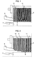
- Fig. 1 is a cross sectional view of a first embodiment of a rotating electrical machine according to the invention in which a stator core 4 is viewed in a circumferential direction.
- Fig. 1 shows a half of the rotating electrical machine in a diametrical direction and a portion thereof close to an axial end.
- Grain oriented magnetic steel sheets 10 are laminated at an axial end of the stator core 4
- non-oriented magnetic steel sheets 11 are laminated at an axial central portion of the stator core, and the respective steel sheets are formed by split pieces punched from a steel strip in a direction, in which teeth 1 are perpendicular to a direction of rolling as shown in Fig. 11A .
- a circumferential direction of the stator core substantially corresponds to the direction of rolling and a diametrical direction thereof substantially corresponds to a vertical direction to the direction of rolling.
- magnetic steel sheets which are different in magnetic permeability in the diametrical direction are laminated at an axial end of and at an axial central portion of the stator core 4.
- magnetic steel sheets used generally in rotating electrical machines are employed as magnetic steel sheets used for the stator core 4.
- the grain oriented magnetic steel sheets 10 are excellent in magnetic permeability generally in a direction of rolling as compared with the non-oriented magnetic steel sheets 11 but low in magnetic permeability in a direction perpendicular to the direction of rolling as compared with the non-oriented magnetic steel sheets 11.
- heat generation at the teeth of the non-oriented magnetic steel sheets 11 is smaller than heat generation at the teeth of the grain oriented magnetic steel sheets 10.
- a magnetic permeability at a magnetic flux density of 1.5T may be used as an index of easiness of pass of a magnetic flux in the teeth 1. While a magnetic steel sheet used generally in rotating electrical machines has a saturation magnetization in the order of 2T, its magnetization characteristic is considerably changed in inclination around 1.5T. In the case where the magnetic flux density in the diametrical direction becomes one close to a saturation magnetization, magnetic resistance increases and correspondingly loss increases.
- a magnetic permeability at 1.5T is adopted as an index of easiness of pass of magnetic flux in the teeth 1 of the stator core 4, and a material is selected so that the non-oriented magnetic steel sheets 11 are superior to the grain oriented magnetic steel sheets 10 in magnetic permeability at a magnetic flux density of 1.5T in the diametrical direction.
- that portion, on which the grain oriented magnetic steel sheets 10 are laminated, corresponds to an axial end of the stator core 4 and that portion, on which the non-oriented magnetic steel sheets 11 are laminated, corresponds to an axial central portion of the stator core 4.
- Fig. 3 is a cross sectional view of a path, along which a cooling medium flows, in a second embodiment of the invention and a stator core 4 as viewed in a circumferential direction, and Fig. 3 shows a half region of the second embodiment in a diametrical direction and a half region of the second embodiment in an axial direction.
- Arrows in the drawing indicate a direction, in which a cooling medium flows, and the cooling medium which is increased in pressure by a fan 23 gets to a stator core 4 through a rotor 7 and an air gap 24 to be exhausted through cooling ducts (not shown), or to be circulated again into the path through a heat exchanger, while cooling an armature winding 6 and the stator core 4.
- Fig. 2 shows a structure of the stator core 4 in the second embodiment of the invention.
- an axial spacing between cooling ducts 5 in an axial central region of the stator core 4 is made smaller as compared with an average axial spacing of the cooling ducts, which is obtained by dividing an axial length of the stator core by the total number of cooling ducts, so that flow rate of the cooling medium through the axial central region of the stator core 4 is increased.
- a magnetic material is decreased in volume in an area, in which the number of cooling ducts is increased, so that an increase in magnetic flux density of the core and an increase in loss are caused.
- stator core 4 magnetic steel sheets used generally in rotating electrical machines are employed as steel sheets used for the stator core 4.
- the stator core 4 is formed from split pieces each punched from a steel strip as shown in Fig. 11A such that a plurality of the grain oriented magnetic steel sheets 10 are laminated at an axial end, at which axial spacings between the cooling ducts 5 are larger than an average spacing, and a plurality of the non-oriented magnetic steel sheets 11 are laminated in an axial central region, in which axial spacings between the cooling ducts 5 are smaller than the average spacing.
- the axial central region in which axial spacings between the cooling ducts 5 are smaller than the average spacing, is high in magnetic permeability in a diametrical direction, and paying an attention to heat generated in the teeth, it is possible to reduce heat generated from the teeth of the stator core 4 in an area, in which the non-oriented magnetic steel sheets 11 are used, as compared with heat generated in an area, in which the grain oriented magnetic steel sheets 10 are used.
- Fig. 6 is a view showing the stator core 4 as viewed from a side of a rotor as indicated by an arrow "B" in Fig. 2 .
- duct spacing pieces 8 arranged between a stator core formed by laminating the grain oriented magnetic steel sheets 10 and a stator core formed by laminating the non-oriented magnetic steel sheets 11 are formed from a non-magnetic material.
- the number of cooling ducts is 11 and axial spacings between the cooling ducts and steel sheets, respectively, are two in kind for the simplicity of the drawings, but the number of cooling ducts may be several tens or more and axial spacings between the cooling ducts and steel sheets may be three or more in kind.
- a portion of three packets, in which the grain oriented magnetic steel sheets 10 are laminated corresponds to the axial end of the stator core 4 and a portion of the remaining packets, in which the non-oriented magnetic steel sheets 11 are laminated, in Fig. 2 corresponds to the axially central portion of the stator core 4.
- Fig. 4 shows a path, along which a cooling medium flows, in a third embodiment of the invention.
- Fig. 4 is a cross sectional view as viewed in a circumferential direction, and shows a half region of the third embodiment in a diametrical direction and a half region of the third embodiment in an axial direction.
- Arrows in the drawing indicate a direction, in which a cooling medium flows, and the cooling medium, which is increased in pressure by a fan 23 for flowing of the cooling medium, goes through a rotor 7 and an air gap 24 to cool a stator core 4 and an armature winding 6 in exhaust sections 26, which are positioned at an axial end region and in a axially central region, to be exhausted through cooling ducts (not shown), or to be circulated again into the path through a heat exchanger.
- a part of the cooling medium which is increased in pressure by the fan 23, cools the armature winding 6, then goes through a cooling medium flowing path 25 to cool the stator core 4 and the armature winding 6 in an intake section 27, in which a cooling medium in the machine is caused to flow radially inwardly of the cooling ducts from radially outwardly thereof in an opposite manner to the exhaust section, then joins a cooling medium, which flows through the rotor 7 and the air gap 24, in the air gap 24, and is exhausted through cooling ducts (not shown) in the exhaust sections 26, or circulated again into the path through a heat exchanger.
- Fig. 5 shows a structure of the stator core in the third embodiment of the invention.
- non-oriented magnetic steel sheets 11 are laminated to form the exhaust section 26b positioned in an axial central region
- grain oriented magnetic steel sheets 10 are laminated to form the exhaust section 26a other than the exhaust section 26b, and the intake sections 27a, 27b.
- the non-oriented magnetic steel sheets 11 are made of split pieces punched from a steel strip as shown in Fig. 11A .
- the exhaust section 26b and positioned downstream of the cooling medium flowing path is expected to be increased in temperature since the cooling medium flows there into after mainly passing through the intake sections 27a, 27b.
- an axial spacing between the cooling ducts in the exhaust section 26b is made smaller than an average one in order to increase the quantity of a cooling medium flowing in the exhaust section 26b positioned in the axial central region.
- the exhaust section 26a at the axial end region of the stator core 4 comprises three packets arranged with the cooling ducts 5 there between, in each of which packets a plurality of the grain oriented magnetic steel sheets 10 are laminated
- the intake sections 27a, 27b positioned in an axial central region comprise two packets arranged with the cooling ducts 5 there between, in each of which packets a plurality of the grain oriented magnetic steel sheets 10 are laminated
- the exhaust section 26b positioned in the axial central region comprises three packets arranged with the cooling ducts 5 there between, in each of which packets a plurality of the non-oriented magnetic steel sheets 11 are laminated, whereby the stator core 4 is formed.
- one packet of the intake sections 27a, 27b positioned at the axial end region, at which the plurality of the grain oriented magnetic steel sheets 10 are laminated, are largest in axial width
- one packet of the exhaust section 26a positioned at the axial end region, at which the plurality of the grain oriented magnetic steel sheets 10 are laminated is large next thereto in axial width
- one packet of the exhaust section 26b positioned in the axial central region, in which the plurality of the non-oriented magnetic steel sheets 11 are laminated is smallest in axial width. It does not matter if one packet of the exhaust section 26a positioned at the axial end region is the same in axial width as one packet of the intake sections 27a, 27b positioned in the axial central region.
- the non-oriented magnetic steel sheets 11 are laminated only in the exhaust section 26b since it is expected that the exhaust section 26b, through which a cooling medium passing through the intake sections 27a, 27b positioned in the axial central region and a cooling medium passing through the rotor 7 flow, is high in cooling medium temperature.
- the magnetic permeability at 1.5T is adopted as an index of easiness, with which a magnetic flux passes in the teeth of the stator core, and a material is selected so that the non-oriented magnetic steel sheets 11 are excellent as compared with the grain oriented magnetic steel sheets in magnetic permeability in a diametrical direction of the grain oriented magnetic steel sheets 10 and the non-oriented magnetic steel sheets 11.
- the number of ventilating sections is 7 and the number of cooling ducts is 17 for the simplicity of the drawings, but the number of ventilating sections may be several except 7 and the number of cooling ducts may be several tens or more.
- the magnetic permeability in a magnetic field of 5000A/m may be adopted as an index of easiness, with which a magnetic flux passes in the teeth, instead of the magnetic permeability at a magnetic flux density of 1.5T.
- the exhaust section 26a comprising three packets, in which the grain oriented magnetic steel sheets 10 are laminated, is positioned at the axial end region of the stator core 4, and the exhaust section 26b and the intake sections 27a, 27b are positioned in the axial central region of the stator core 4.
- Fig. 7 is an enlarged view showing a core in a fourth embodiment of the invention and shows a stator core as viewed from a side of a rotor as indicated by an arrow C in Fig. 1 .
- the core is structured so that non-oriented magnetic steel sheets 11 are laminated centrally in an axial direction and grain oriented magnetic steel sheets 10 are laminated at an axial end.
- non-oriented magnetic steel sheets 33 having a thickness of 0.5 mm are laminated centrally in the axial direction
- grain oriented magnetic steel sheets 34 having a thickness of 0.35 mm are laminated at the axial end
- all insulating varnish layers 32 applied between the steel sheets have the same thickness.
- heat conduction in the steel sheets is good in an inplane direction as compared with that in a direction of lamination, so that heat conduction to a core back from teeth is made favorable in a central area, in which the non-oriented magnetic steel sheets 33 having a thickness of 0.5 mm are laminated, thus enabling moderating a temperature rise in the vicinity of a winding.
- a steel sheet having the equivalent, specific resistance and a thickness of 0.5 mm there is a possibility of an increase in eddy current loss as compared with a magnetic steel sheet having a thickness of 0.35 mm.
- a steel sheet having a thickness of 0.5 mm and a high specific resistance as compared with that of a magnetic steel sheet having a thickness of 0.35 mm is used to enable achieving an increase in core volume while achieving reduction in eddy current loss.
- Fig. 13 is an enlarged view of a core in a fifth embodiment of the invention, and shows a stator core as viewed from a side of a rotor as indicated by the arrow B in Figs. 2 and 5 .
- non-oriented magnetic steel sheets 33 having a thickness of 0.5 mm are laminated in an area, in which an axial spacing between cooling ducts is small, or in an exhaust section, grain oriented magnetic steel sheets 34 having a thickness of 0.35 mm are laminated in an area, in which an axial spacing between cooling ducts is large, and all insulating varnish layers 32 applied between the magnetic steel sheets have the same thickness.
- the non-oriented magnetic steel sheets 33 having a thickness of 0.5 mm are laminated in an area, in which an axial spacing between cooling ducts is small, to increase a magnetic material in volume and to restrict an increase in magnetic flux density to decrease the quantity of magnetic fluxes, which go round in an axial direction.
- the non-oriented magnetic steel sheets 33 having a thickness of 0.5 mm are laminated in the exhaust section to make heat conduction to a core back from teeth favorable as compared with that section, in which the grain oriented magnetic steel sheets 34 having a thickness of 0.35 mm are laminated, thus enabling moderating a temperature rise in the vicinity of a winding.
- a magnetic steel sheet having the equivalent specific resistance and a thickness of 0.5 mm there is a possibility of an increase in eddy current loss as compared with the use of a magnetic steel sheet having a thickness of 0.35 mm.
- a magnetic steel sheet having a thickness of 0.5 mm and a high specific resistance as compared with that of a magnetic steel sheet having a thickness of 0.35 mm is used to enable an increase in core volume while achieving reduction in eddy current loss.
Landscapes
- Engineering & Computer Science (AREA)
- Power Engineering (AREA)
- Iron Core Of Rotating Electric Machines (AREA)
Priority Applications (2)
| Application Number | Priority Date | Filing Date | Title |
|---|---|---|---|
| EP11167880.1A EP2362523B1 (fr) | 2008-04-25 | 2009-04-23 | Machine électrique tournante |
| EP11167890.0A EP2362524B1 (fr) | 2008-04-25 | 2009-04-23 | Machine électrique rotative |
Applications Claiming Priority (2)
| Application Number | Priority Date | Filing Date | Title |
|---|---|---|---|
| JP2008114765 | 2008-04-25 | ||
| JP2009101527A JP4528865B2 (ja) | 2008-04-25 | 2009-04-20 | 回転電機 |
Related Child Applications (2)
| Application Number | Title | Priority Date | Filing Date |
|---|---|---|---|
| EP11167880.1 Division-Into | 2011-05-27 | ||
| EP11167890.0 Division-Into | 2011-05-27 |
Publications (3)
| Publication Number | Publication Date |
|---|---|
| EP2112742A2 true EP2112742A2 (fr) | 2009-10-28 |
| EP2112742A3 EP2112742A3 (fr) | 2011-06-15 |
| EP2112742B1 EP2112742B1 (fr) | 2013-06-12 |
Family
ID=40775187
Family Applications (3)
| Application Number | Title | Priority Date | Filing Date |
|---|---|---|---|
| EP11167880.1A Active EP2362523B1 (fr) | 2008-04-25 | 2009-04-23 | Machine électrique tournante |
| EP20090158652 Active EP2112742B1 (fr) | 2008-04-25 | 2009-04-23 | Machine électrique rotative |
| EP11167890.0A Active EP2362524B1 (fr) | 2008-04-25 | 2009-04-23 | Machine électrique rotative |
Family Applications Before (1)
| Application Number | Title | Priority Date | Filing Date |
|---|---|---|---|
| EP11167880.1A Active EP2362523B1 (fr) | 2008-04-25 | 2009-04-23 | Machine électrique tournante |
Family Applications After (1)
| Application Number | Title | Priority Date | Filing Date |
|---|---|---|---|
| EP11167890.0A Active EP2362524B1 (fr) | 2008-04-25 | 2009-04-23 | Machine électrique rotative |
Country Status (3)
| Country | Link |
|---|---|
| US (3) | US8624462B2 (fr) |
| EP (3) | EP2362523B1 (fr) |
| JP (1) | JP4528865B2 (fr) |
Cited By (3)
| Publication number | Priority date | Publication date | Assignee | Title |
|---|---|---|---|---|
| EP2375545A1 (fr) * | 2010-04-06 | 2011-10-12 | Converteam Technology Ltd | Machines électriques |
| EP2765684A3 (fr) * | 2013-02-08 | 2018-03-28 | Hitachi, Ltd. | Machine électrique rotative |
| CN110635588A (zh) * | 2018-08-31 | 2019-12-31 | 北京金风科创风电设备有限公司 | 电磁装置中铁心的介质输运和换热装置及涡流分离器 |
Families Citing this family (27)
| Publication number | Priority date | Publication date | Assignee | Title |
|---|---|---|---|---|
| CN101588092B (zh) * | 2008-04-25 | 2012-10-10 | 株式会社日立制作所 | 旋转电机 |
| JP4528865B2 (ja) * | 2008-04-25 | 2010-08-25 | 株式会社日立製作所 | 回転電機 |
| EP2333934B1 (fr) * | 2009-12-08 | 2016-07-20 | Siemens Aktiengesellschaft | Agencement pour assurer un entrefer dans une machine électrique |
| US20110221288A1 (en) * | 2010-03-10 | 2011-09-15 | General Electric Company | System and method for cooling in electric machines |
| DE102010029986A1 (de) * | 2010-06-11 | 2011-12-15 | Siemens Aktiengesellschaft | Dynamoelektrische Maschine mit Luft-Flüssigkeitskühlung |
| KR101196607B1 (ko) * | 2010-06-16 | 2012-11-02 | 엘지이노텍 주식회사 | 스핀들 모터 |
| US20120169159A1 (en) * | 2011-01-05 | 2012-07-05 | General Electric Company | Apparatus for ventilating stator core |
| CN102817858B (zh) * | 2011-06-08 | 2017-04-19 | 富准精密工业(深圳)有限公司 | 定子及具有该定子的散热风扇 |
| JP5734765B2 (ja) | 2011-06-24 | 2015-06-17 | トヨタ自動車株式会社 | 回転電機の冷却構造 |
| KR101243291B1 (ko) | 2011-08-23 | 2013-03-13 | 한국전기연구원 | 공랭식 고정자코일 냉각장치 |
| KR101539849B1 (ko) * | 2013-09-23 | 2015-07-28 | 뉴모텍(주) | 절연 코팅에 적합한 구조를 갖는 모터의 적층 코어 |
| JP6226194B2 (ja) * | 2014-03-06 | 2017-11-08 | 株式会社デンソー | 回転電機の固定子 |
| DE102014111239B4 (de) * | 2014-08-07 | 2016-07-21 | Schuler Pressen Gmbh | Blechpaket eines Stators oder eines Läufers sowie eine elektrische Maschine |
| EP2993767A1 (fr) * | 2014-09-08 | 2016-03-09 | Siemens Aktiengesellschaft | Générateur pour une centrale |
| CN104967226A (zh) * | 2015-07-28 | 2015-10-07 | 梁洪炘 | 一种定子磁芯及其制造工艺和包含该定子磁芯的无刷电机 |
| CN105322669A (zh) * | 2015-11-17 | 2016-02-10 | 天津市天发重型水电设备制造有限公司 | 一种发电机定子铁心端部冲片的齿部开沟槽的改进结构 |
| WO2017090571A1 (fr) * | 2015-11-27 | 2017-06-01 | 日本電産株式会社 | Moteur et procédé de fabrication de moteur |
| JP6518221B2 (ja) * | 2016-09-27 | 2019-05-22 | ミネベアミツミ株式会社 | モータ用コア及びモータ |
| JP2019187082A (ja) * | 2018-04-10 | 2019-10-24 | 株式会社東芝 | 回転電機の固定子及び回転電機の固定子の製造方法 |
| JP2019216149A (ja) * | 2018-06-11 | 2019-12-19 | トヨタ自動車株式会社 | コアに用いるための積層体 |
| EP3832849A4 (fr) | 2018-07-27 | 2021-08-25 | Mitsubishi Electric Corporation | Moteur électrique, compresseur, et climatiseur |
| KR102182353B1 (ko) * | 2019-08-13 | 2020-11-24 | 두산중공업 주식회사 | 회전 전기 기계 |
| KR102182354B1 (ko) * | 2019-08-14 | 2020-11-24 | 두산중공업 주식회사 | 회전 전기 기계 |
| DE102020202337A1 (de) * | 2020-02-24 | 2021-08-26 | BSH Hausgeräte GmbH | Wäschepflegegerät mit elektrischem Antrieb |
| DE102020125897A1 (de) | 2020-10-02 | 2022-04-07 | Vacuumschmelze Gmbh & Co. Kg | Blechpaket, elektrische Maschine und Verfahren zum Herstellen eines Blechpakets |
| DE102022132790A1 (de) | 2022-12-09 | 2024-06-20 | Dr. Ing. H.C. F. Porsche Aktiengesellschaft | Elektrische Maschine mit einem Blechpaket |
| JP2025044381A (ja) * | 2023-09-20 | 2025-04-02 | 株式会社ミクニ | 永久磁石埋込型モータ及びポンプ装置 |
Citations (6)
| Publication number | Priority date | Publication date | Assignee | Title |
|---|---|---|---|---|
| US3812392A (en) | 1973-03-09 | 1974-05-21 | Gen Electric | Composite armature core for dynamoelectric machine |
| JPS60141138A (ja) | 1983-12-28 | 1985-07-26 | Hitachi Ltd | 回転電機の固定子 |
| FR2806851A1 (fr) | 2000-03-21 | 2001-09-28 | Valeo Equip Electr Moteur | Machine electrique tournante dont le stator comporte un empilage axial de plaques de tole de permeabilites magnetiques differentes |
| EP1633031A2 (fr) | 2004-09-01 | 2006-03-08 | Hitachi, Ltd. | Machine électrique tournante |
| EP1646127A2 (fr) | 2004-10-05 | 2006-04-12 | Kabushiki Kaisha Toshiba | Machine eléctrodynamique tournante et son enroulement d'induit |
| JP2006340488A (ja) | 2005-06-01 | 2006-12-14 | Toshiba Corp | 回転電機 |
Family Cites Families (26)
| Publication number | Priority date | Publication date | Assignee | Title |
|---|---|---|---|---|
| US2554226A (en) * | 1949-12-30 | 1951-05-22 | Gen Electric | Dynamoelectric machine core mounting |
| GB827223A (en) | 1956-01-09 | 1960-02-03 | Bbc Brown Boveri & Cie | Stator for electrical machines |
| US3475631A (en) * | 1967-08-08 | 1969-10-28 | Westinghouse Electric Corp | Canned motor pump |
| US3739208A (en) * | 1971-12-03 | 1973-06-12 | Gen Electric | Reverse flow cooling system for a dynamoelectric machine |
| US4286183A (en) * | 1977-03-17 | 1981-08-25 | Westinghouse Electric Corp. | Dynamoelectric machine |
| JPS56133952A (en) * | 1980-03-24 | 1981-10-20 | Hitachi Ltd | Salient pole type electric rotary machine |
| JPS5793058U (fr) * | 1980-11-26 | 1982-06-08 | ||
| JPS6162334A (ja) * | 1984-08-30 | 1986-03-31 | Mitsubishi Electric Corp | 回転電機 |
| US4609840A (en) * | 1984-11-05 | 1986-09-02 | General Electric Company | Baffle for improving coolant gas flow distribution in the gap region of a gas cooled dynamoelectric machine |
| US5172020A (en) * | 1990-12-18 | 1992-12-15 | Kabushiki Kaisha Toshiba | Magnetic core for AC electrical equipments |
| US6231685B1 (en) * | 1995-12-28 | 2001-05-15 | Ltv Steel Company, Inc. | Electrical steel with improved magnetic properties in the rolling direction |
| JP2000050539A (ja) | 1998-07-28 | 2000-02-18 | Toshiba Corp | 回転電機の固定子鉄心、固定子鉄心用鋼板部品、固定子鉄心の製造方法および固定子鉄心用鋼板部品の製造方法 |
| JP3289698B2 (ja) * | 1998-11-25 | 2002-06-10 | 株式会社日立製作所 | 回転電機 |
| JP2000308311A (ja) * | 1999-04-14 | 2000-11-02 | Hitachi Ltd | 回転電機 |
| WO2001018943A1 (fr) * | 1999-09-03 | 2001-03-15 | Hitachi, Ltd. | Machine dynamo-electrique |
| US6737768B2 (en) * | 2000-03-31 | 2004-05-18 | Hitachi, Ltd. | Rotating electric machine |
| WO2002071577A1 (fr) * | 2001-03-07 | 2002-09-12 | Hitachi, Ltd. | Machine electrique rotative |
| EP1279747B1 (fr) * | 2001-07-24 | 2013-11-27 | JFE Steel Corporation | Procédé pour la fabrication de tôles d'acier électrique à grains orientés |
| US6943469B2 (en) * | 2002-11-01 | 2005-09-13 | Siemens Westinghouse Power Corporation | Supplemented zonal ventilation system for electric generator |
| US7057324B2 (en) | 2002-12-19 | 2006-06-06 | General Electric Company | Silicon steel punching orientation modifications to lower eddy current losses at the stator core end of dynamoelectric machines |
| JP2004328986A (ja) * | 2003-01-14 | 2004-11-18 | Toyo Tetsushin Kogyo Kk | モータ用固定子コアおよびその製造方法 |
| GB0312871D0 (en) * | 2003-06-05 | 2003-07-09 | Rolls Royce Plc | A stator core |
| US7265473B2 (en) * | 2003-08-28 | 2007-09-04 | General Electric Company | Reduction of core-end losses of dynamoelectric machines by using lower core loss iron silicon punching |
| US6987337B2 (en) * | 2004-01-09 | 2006-01-17 | Siemens Westinghouse Power Corporation | Cam locked air gap baffle assembly for a dynamoelectric machine |
| CH698519B1 (de) * | 2006-01-24 | 2009-08-31 | Alstom Technology Ltd | Pressplattenbleche eines Statorblechkörpers einer elektrischen Maschine. |
| JP4528865B2 (ja) * | 2008-04-25 | 2010-08-25 | 株式会社日立製作所 | 回転電機 |
-
2009
- 2009-04-20 JP JP2009101527A patent/JP4528865B2/ja active Active
- 2009-04-23 EP EP11167880.1A patent/EP2362523B1/fr active Active
- 2009-04-23 EP EP20090158652 patent/EP2112742B1/fr active Active
- 2009-04-23 EP EP11167890.0A patent/EP2362524B1/fr active Active
- 2009-04-23 US US12/428,875 patent/US8624462B2/en active Active
-
2011
- 2011-02-25 US US13/035,395 patent/US8304953B2/en active Active
- 2011-02-25 US US13/035,291 patent/US8174156B2/en active Active
Patent Citations (6)
| Publication number | Priority date | Publication date | Assignee | Title |
|---|---|---|---|---|
| US3812392A (en) | 1973-03-09 | 1974-05-21 | Gen Electric | Composite armature core for dynamoelectric machine |
| JPS60141138A (ja) | 1983-12-28 | 1985-07-26 | Hitachi Ltd | 回転電機の固定子 |
| FR2806851A1 (fr) | 2000-03-21 | 2001-09-28 | Valeo Equip Electr Moteur | Machine electrique tournante dont le stator comporte un empilage axial de plaques de tole de permeabilites magnetiques differentes |
| EP1633031A2 (fr) | 2004-09-01 | 2006-03-08 | Hitachi, Ltd. | Machine électrique tournante |
| EP1646127A2 (fr) | 2004-10-05 | 2006-04-12 | Kabushiki Kaisha Toshiba | Machine eléctrodynamique tournante et son enroulement d'induit |
| JP2006340488A (ja) | 2005-06-01 | 2006-12-14 | Toshiba Corp | 回転電機 |
Cited By (6)
| Publication number | Priority date | Publication date | Assignee | Title |
|---|---|---|---|---|
| EP2375545A1 (fr) * | 2010-04-06 | 2011-10-12 | Converteam Technology Ltd | Machines électriques |
| WO2011124328A3 (fr) * | 2010-04-06 | 2011-12-01 | Converteam Technology Ltd | Machines électriques |
| US9293953B2 (en) | 2010-04-06 | 2016-03-22 | Ge Energy Power Conversion Technology, Ltd. | Apparatus and method for cooling components for electrical machines |
| EP2765684A3 (fr) * | 2013-02-08 | 2018-03-28 | Hitachi, Ltd. | Machine électrique rotative |
| CN110635588A (zh) * | 2018-08-31 | 2019-12-31 | 北京金风科创风电设备有限公司 | 电磁装置中铁心的介质输运和换热装置及涡流分离器 |
| CN110635588B (zh) * | 2018-08-31 | 2020-08-11 | 北京金风科创风电设备有限公司 | 电磁装置中铁心的介质输运和换热装置及涡流分离器 |
Also Published As
| Publication number | Publication date |
|---|---|
| JP4528865B2 (ja) | 2010-08-25 |
| US8624462B2 (en) | 2014-01-07 |
| US20090267428A1 (en) | 2009-10-29 |
| US8174156B2 (en) | 2012-05-08 |
| US20110140566A1 (en) | 2011-06-16 |
| US20110140582A1 (en) | 2011-06-16 |
| EP2362524B1 (fr) | 2013-12-04 |
| US8304953B2 (en) | 2012-11-06 |
| EP2112742A3 (fr) | 2011-06-15 |
| JP2009284756A (ja) | 2009-12-03 |
| EP2362523A1 (fr) | 2011-08-31 |
| EP2362523B1 (fr) | 2013-12-11 |
| EP2362524A1 (fr) | 2011-08-31 |
| EP2112742B1 (fr) | 2013-06-12 |
Similar Documents
| Publication | Publication Date | Title |
|---|---|---|
| US8624462B2 (en) | Rotating electrical machine | |
| JP5130321B2 (ja) | 回転電機 | |
| JP4660406B2 (ja) | 回転電機 | |
| CN104702002B (zh) | 旋转电机 | |
| JP6627784B2 (ja) | 回転電機ロータ | |
| CN101809847B (zh) | 轴向间隙型无芯旋转机 | |
| JP5260563B2 (ja) | 永久磁石式発電機またはモータ | |
| EP1763121A2 (fr) | Machine électrique de rotation | |
| CN100414813C (zh) | 旋转电机 | |
| JP4901839B2 (ja) | 電動機及び圧縮機及び送風機及び換気扇 | |
| CN104380576B (zh) | 旋转电机的定子 | |
| JP5630057B2 (ja) | 回転電気機械 | |
| JP2008167520A (ja) | 回転電機 | |
| CN203896058U (zh) | 永磁式旋转电机及电梯驱动提升机 | |
| JP6440349B2 (ja) | 回転電機 | |
| JP6169496B2 (ja) | 永久磁石式回転電機 | |
| JP7203175B1 (ja) | 回転電機 | |
| JP2013153609A (ja) | 回転電機 | |
| JP2009268245A (ja) | 回転電機の固定子 | |
| JP2016086602A (ja) | 回転電機 | |
| JP2012147589A (ja) | 回転電機 | |
| JP2006340488A (ja) | 回転電機 | |
| JP2010136460A (ja) | 回転電機 | |
| JP3797752B2 (ja) | 回転電機の固定子 | |
| JP2005168109A (ja) | 回転電機 |
Legal Events
| Date | Code | Title | Description |
|---|---|---|---|
| PUAI | Public reference made under article 153(3) epc to a published international application that has entered the european phase |
Free format text: ORIGINAL CODE: 0009012 |
|
| 17P | Request for examination filed |
Effective date: 20090514 |
|
| AK | Designated contracting states |
Kind code of ref document: A2 Designated state(s): AT BE BG CH CY CZ DE DK EE ES FI FR GB GR HR HU IE IS IT LI LT LU LV MC MK MT NL NO PL PT RO SE SI SK TR |
|
| PUAL | Search report despatched |
Free format text: ORIGINAL CODE: 0009013 |
|
| AK | Designated contracting states |
Kind code of ref document: A3 Designated state(s): AT BE BG CH CY CZ DE DK EE ES FI FR GB GR HR HU IE IS IT LI LT LU LV MC MK MT NL NO PL PT RO SE SI SK TR |
|
| AX | Request for extension of the european patent |
Extension state: AL BA RS |
|
| GRAP | Despatch of communication of intention to grant a patent |
Free format text: ORIGINAL CODE: EPIDOSNIGR1 |
|
| GRAS | Grant fee paid |
Free format text: ORIGINAL CODE: EPIDOSNIGR3 |
|
| GRAA | (expected) grant |
Free format text: ORIGINAL CODE: 0009210 |
|
| AK | Designated contracting states |
Kind code of ref document: B1 Designated state(s): AT BE BG CH CY CZ DE DK EE ES FI FR GB GR HR HU IE IS IT LI LT LU LV MC MK MT NL NO PL PT RO SE SI SK TR |
|
| REG | Reference to a national code |
Ref country code: GB Ref legal event code: FG4D |
|
| REG | Reference to a national code |
Ref country code: CH Ref legal event code: EP |
|
| REG | Reference to a national code |
Ref country code: AT Ref legal event code: REF Ref document number: 616999 Country of ref document: AT Kind code of ref document: T Effective date: 20130615 |
|
| REG | Reference to a national code |
Ref country code: IE Ref legal event code: FG4D |
|
| REG | Reference to a national code |
Ref country code: DE Ref legal event code: R096 Ref document number: 602009016347 Country of ref document: DE Effective date: 20130808 |
|
| REG | Reference to a national code |
Ref country code: NL Ref legal event code: T3 |
|
| REG | Reference to a national code |
Ref country code: SE Ref legal event code: TRGR |
|
| PG25 | Lapsed in a contracting state [announced via postgrant information from national office to epo] |
Ref country code: NO Free format text: LAPSE BECAUSE OF FAILURE TO SUBMIT A TRANSLATION OF THE DESCRIPTION OR TO PAY THE FEE WITHIN THE PRESCRIBED TIME-LIMIT Effective date: 20130912 Ref country code: GR Free format text: LAPSE BECAUSE OF FAILURE TO SUBMIT A TRANSLATION OF THE DESCRIPTION OR TO PAY THE FEE WITHIN THE PRESCRIBED TIME-LIMIT Effective date: 20130913 Ref country code: ES Free format text: LAPSE BECAUSE OF FAILURE TO SUBMIT A TRANSLATION OF THE DESCRIPTION OR TO PAY THE FEE WITHIN THE PRESCRIBED TIME-LIMIT Effective date: 20130923 Ref country code: SI Free format text: LAPSE BECAUSE OF FAILURE TO SUBMIT A TRANSLATION OF THE DESCRIPTION OR TO PAY THE FEE WITHIN THE PRESCRIBED TIME-LIMIT Effective date: 20130612 Ref country code: FI Free format text: LAPSE BECAUSE OF FAILURE TO SUBMIT A TRANSLATION OF THE DESCRIPTION OR TO PAY THE FEE WITHIN THE PRESCRIBED TIME-LIMIT Effective date: 20130612 Ref country code: LT Free format text: LAPSE BECAUSE OF FAILURE TO SUBMIT A TRANSLATION OF THE DESCRIPTION OR TO PAY THE FEE WITHIN THE PRESCRIBED TIME-LIMIT Effective date: 20130612 |
|
| REG | Reference to a national code |
Ref country code: AT Ref legal event code: MK05 Ref document number: 616999 Country of ref document: AT Kind code of ref document: T Effective date: 20130612 |
|
| REG | Reference to a national code |
Ref country code: LT Ref legal event code: MG4D |
|
| PG25 | Lapsed in a contracting state [announced via postgrant information from national office to epo] |
Ref country code: HR Free format text: LAPSE BECAUSE OF FAILURE TO SUBMIT A TRANSLATION OF THE DESCRIPTION OR TO PAY THE FEE WITHIN THE PRESCRIBED TIME-LIMIT Effective date: 20130612 Ref country code: BG Free format text: LAPSE BECAUSE OF FAILURE TO SUBMIT A TRANSLATION OF THE DESCRIPTION OR TO PAY THE FEE WITHIN THE PRESCRIBED TIME-LIMIT Effective date: 20130912 |
|
| PG25 | Lapsed in a contracting state [announced via postgrant information from national office to epo] |
Ref country code: LV Free format text: LAPSE BECAUSE OF FAILURE TO SUBMIT A TRANSLATION OF THE DESCRIPTION OR TO PAY THE FEE WITHIN THE PRESCRIBED TIME-LIMIT Effective date: 20130612 |
|
| PG25 | Lapsed in a contracting state [announced via postgrant information from national office to epo] |
Ref country code: IS Free format text: LAPSE BECAUSE OF FAILURE TO SUBMIT A TRANSLATION OF THE DESCRIPTION OR TO PAY THE FEE WITHIN THE PRESCRIBED TIME-LIMIT Effective date: 20131012 Ref country code: AT Free format text: LAPSE BECAUSE OF FAILURE TO SUBMIT A TRANSLATION OF THE DESCRIPTION OR TO PAY THE FEE WITHIN THE PRESCRIBED TIME-LIMIT Effective date: 20130612 Ref country code: BE Free format text: LAPSE BECAUSE OF FAILURE TO SUBMIT A TRANSLATION OF THE DESCRIPTION OR TO PAY THE FEE WITHIN THE PRESCRIBED TIME-LIMIT Effective date: 20130612 Ref country code: EE Free format text: LAPSE BECAUSE OF FAILURE TO SUBMIT A TRANSLATION OF THE DESCRIPTION OR TO PAY THE FEE WITHIN THE PRESCRIBED TIME-LIMIT Effective date: 20130612 Ref country code: CZ Free format text: LAPSE BECAUSE OF FAILURE TO SUBMIT A TRANSLATION OF THE DESCRIPTION OR TO PAY THE FEE WITHIN THE PRESCRIBED TIME-LIMIT Effective date: 20130612 Ref country code: SK Free format text: LAPSE BECAUSE OF FAILURE TO SUBMIT A TRANSLATION OF THE DESCRIPTION OR TO PAY THE FEE WITHIN THE PRESCRIBED TIME-LIMIT Effective date: 20130612 Ref country code: PT Free format text: LAPSE BECAUSE OF FAILURE TO SUBMIT A TRANSLATION OF THE DESCRIPTION OR TO PAY THE FEE WITHIN THE PRESCRIBED TIME-LIMIT Effective date: 20131014 |
|
| PG25 | Lapsed in a contracting state [announced via postgrant information from national office to epo] |
Ref country code: RO Free format text: LAPSE BECAUSE OF FAILURE TO SUBMIT A TRANSLATION OF THE DESCRIPTION OR TO PAY THE FEE WITHIN THE PRESCRIBED TIME-LIMIT Effective date: 20130612 Ref country code: PL Free format text: LAPSE BECAUSE OF FAILURE TO SUBMIT A TRANSLATION OF THE DESCRIPTION OR TO PAY THE FEE WITHIN THE PRESCRIBED TIME-LIMIT Effective date: 20130612 |
|
| PLBE | No opposition filed within time limit |
Free format text: ORIGINAL CODE: 0009261 |
|
| STAA | Information on the status of an ep patent application or granted ep patent |
Free format text: STATUS: NO OPPOSITION FILED WITHIN TIME LIMIT |
|
| PG25 | Lapsed in a contracting state [announced via postgrant information from national office to epo] |
Ref country code: DK Free format text: LAPSE BECAUSE OF FAILURE TO SUBMIT A TRANSLATION OF THE DESCRIPTION OR TO PAY THE FEE WITHIN THE PRESCRIBED TIME-LIMIT Effective date: 20130612 |
|
| 26N | No opposition filed |
Effective date: 20140313 |
|
| REG | Reference to a national code |
Ref country code: DE Ref legal event code: R097 Ref document number: 602009016347 Country of ref document: DE Effective date: 20140313 |
|
| REG | Reference to a national code |
Ref country code: DE Ref legal event code: R082 Ref document number: 602009016347 Country of ref document: DE Representative=s name: PUSCHMANN BORCHERT BARDEHLE PATENTANWAELTE PAR, DE |
|
| REG | Reference to a national code |
Ref country code: NL Ref legal event code: SD Effective date: 20140818 |
|
| REG | Reference to a national code |
Ref country code: DE Ref legal event code: R082 Ref document number: 602009016347 Country of ref document: DE Representative=s name: PUSCHMANN BORCHERT BARDEHLE PATENTANWAELTE PAR, DE Effective date: 20140731 Ref country code: DE Ref legal event code: R081 Ref document number: 602009016347 Country of ref document: DE Owner name: MITSUBISHI HITACHI POWER SYSTEMS, LTD., YOKOHA, JP Free format text: FORMER OWNER: HITACHI, LTD., TOKYO, JP Effective date: 20140731 |
|
| PG25 | Lapsed in a contracting state [announced via postgrant information from national office to epo] |
Ref country code: LU Free format text: LAPSE BECAUSE OF FAILURE TO SUBMIT A TRANSLATION OF THE DESCRIPTION OR TO PAY THE FEE WITHIN THE PRESCRIBED TIME-LIMIT Effective date: 20140423 Ref country code: MC Free format text: LAPSE BECAUSE OF FAILURE TO SUBMIT A TRANSLATION OF THE DESCRIPTION OR TO PAY THE FEE WITHIN THE PRESCRIBED TIME-LIMIT Effective date: 20130612 |
|
| REG | Reference to a national code |
Ref country code: FR Ref legal event code: TP Owner name: MITSUBISHI HITACHI POWER SYSTEMS, LTD., JP Effective date: 20141124 |
|
| REG | Reference to a national code |
Ref country code: CH Ref legal event code: PFUS Owner name: MITSUBISHI HITACHI POWER SYSTEMS, LTD., JP Free format text: FORMER OWNER: HITACHI, LTD., JP |
|
| REG | Reference to a national code |
Ref country code: IE Ref legal event code: MM4A |
|
| PG25 | Lapsed in a contracting state [announced via postgrant information from national office to epo] |
Ref country code: IE Free format text: LAPSE BECAUSE OF NON-PAYMENT OF DUE FEES Effective date: 20140423 |
|
| REG | Reference to a national code |
Ref country code: GB Ref legal event code: 732E Free format text: REGISTERED BETWEEN 20150528 AND 20150603 |
|
| REG | Reference to a national code |
Ref country code: FR Ref legal event code: PLFP Year of fee payment: 8 |
|
| PG25 | Lapsed in a contracting state [announced via postgrant information from national office to epo] |
Ref country code: MT Free format text: LAPSE BECAUSE OF FAILURE TO SUBMIT A TRANSLATION OF THE DESCRIPTION OR TO PAY THE FEE WITHIN THE PRESCRIBED TIME-LIMIT Effective date: 20130612 |
|
| PG25 | Lapsed in a contracting state [announced via postgrant information from national office to epo] |
Ref country code: CY Free format text: LAPSE BECAUSE OF FAILURE TO SUBMIT A TRANSLATION OF THE DESCRIPTION OR TO PAY THE FEE WITHIN THE PRESCRIBED TIME-LIMIT Effective date: 20130612 |
|
| PG25 | Lapsed in a contracting state [announced via postgrant information from national office to epo] |
Ref country code: TR Free format text: LAPSE BECAUSE OF FAILURE TO SUBMIT A TRANSLATION OF THE DESCRIPTION OR TO PAY THE FEE WITHIN THE PRESCRIBED TIME-LIMIT Effective date: 20130612 Ref country code: HU Free format text: LAPSE BECAUSE OF FAILURE TO SUBMIT A TRANSLATION OF THE DESCRIPTION OR TO PAY THE FEE WITHIN THE PRESCRIBED TIME-LIMIT; INVALID AB INITIO Effective date: 20090423 |
|
| REG | Reference to a national code |
Ref country code: FR Ref legal event code: PLFP Year of fee payment: 9 |
|
| REG | Reference to a national code |
Ref country code: FR Ref legal event code: PLFP Year of fee payment: 10 |
|
| PG25 | Lapsed in a contracting state [announced via postgrant information from national office to epo] |
Ref country code: MK Free format text: LAPSE BECAUSE OF FAILURE TO SUBMIT A TRANSLATION OF THE DESCRIPTION OR TO PAY THE FEE WITHIN THE PRESCRIBED TIME-LIMIT Effective date: 20130612 |
|
| REG | Reference to a national code |
Ref country code: DE Ref legal event code: R081 Ref document number: 602009016347 Country of ref document: DE Owner name: MITSUBISHI HEAVY INDUSTRIES, LTD., JP Free format text: FORMER OWNER: MITSUBISHI HITACHI POWER SYSTEMS, LTD., YOKOHAMA-SHI, KANAGAWA, JP Ref country code: DE Ref legal event code: R081 Ref document number: 602009016347 Country of ref document: DE Owner name: MITSUBISHI GENERATOR CO., LTD., KOBE-SHI, JP Free format text: FORMER OWNER: MITSUBISHI HITACHI POWER SYSTEMS, LTD., YOKOHAMA-SHI, KANAGAWA, JP Ref country code: DE Ref legal event code: R082 Ref document number: 602009016347 Country of ref document: DE Representative=s name: PUSCHMANN BORCHERT KAISER KLETTNER PATENTANWAE, DE Ref country code: DE Ref legal event code: R081 Ref document number: 602009016347 Country of ref document: DE Owner name: MITSUBISHI POWER, LTD., YOKOHAMA-SHI, JP Free format text: FORMER OWNER: MITSUBISHI HITACHI POWER SYSTEMS, LTD., YOKOHAMA-SHI, KANAGAWA, JP |
|
| REG | Reference to a national code |
Ref country code: NL Ref legal event code: HC Owner name: MITSUBISHI POWER, LTD.; JP Free format text: DETAILS ASSIGNMENT: CHANGE OF OWNER(S), CHANGE OF OWNER(S) NAME; FORMER OWNER NAME: MITSUBISHI HITACHI POWER SYSTEMS, LTD. Effective date: 20210114 |
|
| REG | Reference to a national code |
Ref country code: CH Ref legal event code: PFA Owner name: MITSUBISHI POWER, LTD., JP Free format text: FORMER OWNER: MITSUBISHI HITACHI POWER SYSTEMS, LTD., JP |
|
| REG | Reference to a national code |
Ref country code: DE Ref legal event code: R081 Ref document number: 602009016347 Country of ref document: DE Owner name: MITSUBISHI HEAVY INDUSTRIES, LTD., JP Free format text: FORMER OWNER: MITSUBISHI POWER, LTD., YOKOHAMA-SHI, KANAGAWA, JP Ref country code: DE Ref legal event code: R081 Ref document number: 602009016347 Country of ref document: DE Owner name: MITSUBISHI GENERATOR CO., LTD., KOBE-SHI, JP Free format text: FORMER OWNER: MITSUBISHI POWER, LTD., YOKOHAMA-SHI, KANAGAWA, JP |
|
| REG | Reference to a national code |
Ref country code: GB Ref legal event code: 732E Free format text: REGISTERED BETWEEN 20230907 AND 20230913 |
|
| REG | Reference to a national code |
Ref country code: NL Ref legal event code: PD Owner name: MITSUBISHI HEAVY INDUSTRIES, LTD.; JP Free format text: DETAILS ASSIGNMENT: CHANGE OF OWNER(S), ASSIGNMENT; FORMER OWNER NAME: MITSUBISHI POWER, LTD. Effective date: 20231024 |
|
| REG | Reference to a national code |
Ref country code: NL Ref legal event code: PD Owner name: MITSUBISHI GENERATOR CO., LTD.; JP Free format text: DETAILS ASSIGNMENT: CHANGE OF OWNER(S), DEMERGER; FORMER OWNER NAME: MITSUBISHI POWER, LTD. Effective date: 20240821 |
|
| REG | Reference to a national code |
Ref country code: DE Ref legal event code: R081 Ref document number: 602009016347 Country of ref document: DE Owner name: MITSUBISHI GENERATOR CO., LTD., KOBE-SHI, JP Free format text: FORMER OWNER: MITSUBISHI HEAVY INDUSTRIES, LTD., TOKYO, JP |
|
| REG | Reference to a national code |
Ref country code: GB Ref legal event code: 732E Free format text: REGISTERED BETWEEN 20241107 AND 20241113 |
|
| REG | Reference to a national code |
Ref country code: DE Ref legal event code: R084 Ref document number: 602009016347 Country of ref document: DE |
|
| PGFP | Annual fee paid to national office [announced via postgrant information from national office to epo] |
Ref country code: DE Payment date: 20250305 Year of fee payment: 17 |
|
| PGFP | Annual fee paid to national office [announced via postgrant information from national office to epo] |
Ref country code: CH Payment date: 20250501 Year of fee payment: 17 |
|
| REG | Reference to a national code |
Ref country code: GB Ref legal event code: 746 Effective date: 20250820 |
|
| PGFP | Annual fee paid to national office [announced via postgrant information from national office to epo] |
Ref country code: SE Payment date: 20260312 Year of fee payment: 18 |
|
| PGFP | Annual fee paid to national office [announced via postgrant information from national office to epo] |
Ref country code: GB Payment date: 20260313 Year of fee payment: 18 |
|
| PGFP | Annual fee paid to national office [announced via postgrant information from national office to epo] |
Ref country code: IT Payment date: 20260320 Year of fee payment: 18 |
|
| PGFP | Annual fee paid to national office [announced via postgrant information from national office to epo] |
Ref country code: NL Payment date: 20260317 Year of fee payment: 18 |
|
| PGFP | Annual fee paid to national office [announced via postgrant information from national office to epo] |
Ref country code: FR Payment date: 20260309 Year of fee payment: 18 |
|
| REG | Reference to a national code |
Ref country code: CH Ref legal event code: U11 Free format text: ST27 STATUS EVENT CODE: U-0-0-U10-U11 (AS PROVIDED BY THE NATIONAL OFFICE) Effective date: 20260501 |