EP2112746A1 - Machine dynamoélectrique - Google Patents
Machine dynamoélectrique Download PDFInfo
- Publication number
- EP2112746A1 EP2112746A1 EP08007796A EP08007796A EP2112746A1 EP 2112746 A1 EP2112746 A1 EP 2112746A1 EP 08007796 A EP08007796 A EP 08007796A EP 08007796 A EP08007796 A EP 08007796A EP 2112746 A1 EP2112746 A1 EP 2112746A1
- Authority
- EP
- European Patent Office
- Prior art keywords
- cooling
- rotor according
- rotor
- cooling channel
- wall
- Prior art date
- Legal status (The legal status is an assumption and is not a legal conclusion. Google has not performed a legal analysis and makes no representation as to the accuracy of the status listed.)
- Withdrawn
Links
- 238000001816 cooling Methods 0.000 claims abstract description 85
- 239000002826 coolant Substances 0.000 claims abstract description 40
- 239000012530 fluid Substances 0.000 claims abstract description 26
- 239000004020 conductor Substances 0.000 claims description 23
- 238000004804 winding Methods 0.000 claims description 16
- 125000006850 spacer group Chemical group 0.000 claims description 5
- UFHFLCQGNIYNRP-UHFFFAOYSA-N Hydrogen Chemical compound [H][H] UFHFLCQGNIYNRP-UHFFFAOYSA-N 0.000 description 12
- 239000000112 cooling gas Substances 0.000 description 8
- 239000001257 hydrogen Substances 0.000 description 7
- 229910052739 hydrogen Inorganic materials 0.000 description 7
- 238000011161 development Methods 0.000 description 6
- 230000018109 developmental process Effects 0.000 description 6
- 239000007789 gas Substances 0.000 description 4
- XLYOFNOQVPJJNP-UHFFFAOYSA-N water Substances O XLYOFNOQVPJJNP-UHFFFAOYSA-N 0.000 description 3
- XEEYBQQBJWHFJM-UHFFFAOYSA-N Iron Chemical compound [Fe] XEEYBQQBJWHFJM-UHFFFAOYSA-N 0.000 description 2
- 238000010438 heat treatment Methods 0.000 description 2
- 238000009413 insulation Methods 0.000 description 2
- 230000004888 barrier function Effects 0.000 description 1
- 239000000498 cooling water Substances 0.000 description 1
- 230000007423 decrease Effects 0.000 description 1
- 238000006073 displacement reaction Methods 0.000 description 1
- 230000000694 effects Effects 0.000 description 1
- 238000005516 engineering process Methods 0.000 description 1
- 238000004880 explosion Methods 0.000 description 1
- 239000002360 explosive Substances 0.000 description 1
- 150000002431 hydrogen Chemical class 0.000 description 1
- 229910052742 iron Inorganic materials 0.000 description 1
- 238000004519 manufacturing process Methods 0.000 description 1
- 239000003973 paint Substances 0.000 description 1
- 230000008646 thermal stress Effects 0.000 description 1
- 239000002918 waste heat Substances 0.000 description 1
Images


Classifications
-
- H—ELECTRICITY
- H02—GENERATION; CONVERSION OR DISTRIBUTION OF ELECTRIC POWER
- H02K—DYNAMO-ELECTRIC MACHINES
- H02K3/00—Details of windings
- H02K3/04—Windings characterised by the conductor shape, form or construction, e.g. with bar conductors
- H02K3/24—Windings characterised by the conductor shape, form or construction, e.g. with bar conductors with channels or ducts for cooling medium between the conductors
-
- H—ELECTRICITY
- H02—GENERATION; CONVERSION OR DISTRIBUTION OF ELECTRIC POWER
- H02K—DYNAMO-ELECTRIC MACHINES
- H02K9/00—Arrangements for cooling or ventilating
Definitions
- the invention relates to a rotor for a dynamoelectric machine, wherein the rotor has cooling channels.
- a dynamoelectric machine is understood as meaning, for example, an electric generator which is heated very strongly during operation so that it must be cooled.
- a dynamoelectric machine is understood to be any energy converter which converts electrical energy into mechanical energy or mechanical energy into electrical energy.
- a dynamoelectric machine is to be understood as a generator for supplying electrical energy.
- a generator as an embodiment of an electric machine consists inter alia of electrically active parts, which include a stator and a rotatably mounted rotor.
- the stator comprises a plurality of stacked segment plates, which are also referred to as segment plates or iron sheets.
- the segment plates are provided with grooves for receiving windings. High magnetizability and small hysteresis or eddy current losses of the segmental plates are advantageous.
- By thin paper, paint or oxide layers, the segment sheets are isolated from each other.
- a completely formed stator consists of many segmented sheets.
- the structure of the stacked segment plates is also referred to as a laminated core.
- Fresh air cooling Fresh air is sucked in via a fan, cleaned by suitable filters and blown into the generator.
- closed Circulation the purified air is blown through the generator in a closed circuit and cooled down in heat exchangers by cooling water. The waste heat can also be used for heating purposes.
- Pure water cooling for generators with high power, specially treated water is led through the generator into a closed circuit.
- Hydrogen cooling the gaseous hydrogen moving in a circuit releases the heat loss via the water coolers on the sides of the generators.
- the housing of the generators must be gas-tight and pressure-resistant, in order to be able to withstand a possible explosive gas explosion. The use of hydrogen gas instead of the air causes lower gas friction losses and double heat removal capability.
- hydrogen gas (H 2 ) is preferably used as the cooling medium, which allows a significantly higher cooling capacity than air, which can be increased by pressurizing the hydrogen gas and carrying out the cooling under excess pressure. Since hydrogen has a higher heat capacity and a higher thermal conductivity than air, the filling of the generator housing with hydrogen, the heat can be better derived from the generator, as would be possible with air. However, the cooling with hydrogen gas requires an additional, not inconsiderable expense, which affects both the purchase and later in the operation cost.
- a concomitant problem with generator cooling with hydrogen gas is the virtually unavoidable losses of hydrogen gas, mainly due to leaks in the shaft passage of the rotor shaft through the housing of the generator. To prevent these losses or at least keep low, the shaft passages are each provided with a shaft seal, which are designed as oil bath seal.
- Another problem is the moisture of the hydrogen cooling gas.
- the insulation components of the generator are usually exposed to the air atmosphere. As a result, moisture from the air is absorbed by the insulation components.
- the moisture accumulated in the insulating components releases the hydrogen to the hydrogen.
- the air circulates in the generator housing and through the coils in the stator.
- the fans are mounted directly on the rotor.
- the cooling gas usually flows via a guide device, which may also be referred to as a compressor diffuser, from a substantially radial direction into the generator, wherein the compressor diffuser can be assigned to the stator and therefore is not a rotatable component.
- the cooling gas is then deflected via a compressor impeller arranged on the rotor and optionally compressed, whereby a cooling gas with optimum physical parameters for cooling the rotor is achieved.
- the available flow cross sections for the cooling gas in the compressor diffuser and in the compressor impeller are adapted to one another in the flow direction.
- a force can act on the rotor causing the rotor to be displaced in an axial direction.
- the force comes from the turbine thrust of the steam turbine or the gas turbine.
- the displacement of the rotor located on the compressor relative to the compressor diffuser causes the flow cross-sections are offset from each other, so that no optimal flow conditions for the cooling gas prevail.
- cooling channels in the electrical conductors, which are then flowed through by a cooling medium.
- the heat transfer of the cooling medium to the electrical conductor is partially unsatisfactory, since the allowable temperatures, especially in the winding head area, can exceed a predetermined limit.
- the heat transfer of the cooling medium is to be improved on the component to be cooled.
- a rotor for a dynamoelectric machine wherein the rotor has cooling channels, wherein in the cooling channel fluid for increasing the heat transfer of a cooling medium flowing during operation through the cooling medium has on the cooling channel.
- fluids are provided which are specially designed to increase the heat transfer of the cooling medium to the cooling channel. It is generally known that a comparatively fast flow of the cooling medium in the cooling channel causes a low heat transfer coefficient to the component to be cooled. A swirling of the cooling medium in the cooling channel would already achieve an improvement of the heat transfer to the component to be cooled.
- the proposed fluids are therefore designed such that they lead to a turbulence of the cooling medium or to an increase in the turbulence in the flow of the cooling medium, which leads to an increase in the heat transfer.
- the cooling channel is delimited by cooling channel walls and the fluid is arranged on a cooling channel wall.
- the fluid can thus be easily and inexpensively placed in the cooling channel manufacturing technology.
- the cooling channel improved according to the invention is used for cooling the winding head. Since the winding head is subjected to relatively high thermal stress and therefore may exceed the permissible limit temperatures during operation, it is advantageous if the winding head is cooled specifically.
- the cooling channel has a first axial conductor cooling channel extending in the axial direction and a second transverse conductor cooling channel extending in the circumferential direction.
- deflection elements are arranged in the cooling channel. These deflection elements cause the flow medium flows through a meandering course in the cooling channel. The flow of the coolant is thereby deflected and decelerated, which leads to an increase in the heat transfer to the cooling channel wall.
- the fluids are designed as dimples. Dimpels are recesses in the canal wall. Known are dimples, for example, from golf. The golf ball has no smooth surface, but recesses or depressions on the surface, which are referred to as dimples. These dimples cause a turbulence of the air or the cooling medium in the cooling channel. A turbulence leads to an increase in the heat transfer to the cooling channel wall.
- the dimples can have different geometric shapes. For example, the dimple may have a circular structure. It is also possible that the dimple has an elliptical, triangular or quadrangular structure.
- the fluid has a projection protruding from the cooling channel wall.
- the projection serves as a barrier for the cooling medium.
- the cooling medium is prevented by the projection from flowing unrestrained in a flow direction.
- the projection leads to an increase in the turbulence of the flow medium. The consequence is that the heat transfer to the cooling channel wall is increased.
- the projection has a distance-longitudinal projection for distancing two cooling-duct walls and turbulence-increasing projections adjacent thereto.
- the turbulence increasing protrusions have a turbulence increasing wall, wherein an impinging cooling medium impinging on the turbulence increasing protrusion wall from a flow direction in operation impinges at an angle of less than 90 °.
- This fluid is therefore formed perpendicular to the flow direction from V-shaped. Therefore, the flow medium is not decelerated frontally by the turbulence increasing projection wall, but rather is reflected at an angle of less than 90 °. The result is that the flow rate decreases, the pressure increases slightly, and thus the turbulence is increased, which leads to an increase in the heat transfer.
- a second turbulence increasing projection is arranged on the spacer projection so that the cooling medium has a turbulence increasing projection wall left and right seen in the flow direction and is deflected thereon at an angle of less than 90 °.
- the FIG. 1 shows a section of a rotor 1 for a dynamoelectric machine.
- the rotor 1 comprises a rotor bale 2 rotatably mounted about a rotation axis (not shown) and electrical conductors 3 arranged in grooves. Furthermore, the rotor 1 has a winding head 4 on a front side.
- the winding head 4 comprises a winding head transverse conductor 5 and a winding head axial conductor 6.
- the rotor 1 rotates at a mains frequency of 50 Hz or 60 Hz.
- the rotor 1 heats up here and must be cooled.
- the individual winding head lines which consist of a winding head transverse conductor 5 and a winding head axial conductor 6, are spaced apart by spacers 7.
- a cooling medium flows via an inlet not shown in detail under a gas guide casing 8 along in a Nutgroundkanal under the electrical conductor 3.
- the cooling medium then flows through radial cooling channels 9 through the electrical conductor 3.
- the flow of the cooling medium is symbolically represented by the cooling flow path 10 ,
- the cooling of the winding head 4 is carried out as follows: the spacer elements 7 are formed such that between two winding head conductors 5, 6, a cooling channel 11 is formed. This cooling channel 11 is bounded by cooling channel walls 12. Via an inlet 13, the cooling medium flows into the cooling channel 11 and in this case is divided into an axial conductor cooling channel 14 and a transverse conductor cooling channel 15. The movement of the cooling medium flowing through the axial conductor cooling channel 14 is symbolized by the axial conductor cooling path 16. The movement of through the transverse conductor cooling channel 15 flowing cooling medium is symbolized by the transverse conductor cooling path 17.
- the cooling medium flowing through the axial conductor cooling path 16 then emerges from the electrical conductor 3 via axial-radial bores 18.
- the cooling medium flowing through the transverse conductor cooling channel 15 flows below the electrical conductors 3 in so-called groove base channels and subsequently emerges via the radial cooling channels 9.
- the cooling channel 11 In the cooling channel 11 are deflection elements 19, which cause the cooling medium has a meandering course 20.
- the cooling channel wall 12 is preferably flat.
- To improve the heat transfer of the cooling medium to the cooling channel wall 12 are in the FIG. 1 invisible fluid 21 is arranged.
- the fluid 21 are designed such that they lead to an increase in the heat transfer of a cooling medium flowing during operation through the cooling channel to the cooling channel 11.
- FIG. 2 an embodiment of the fluid 21 is shown.
- the FIG. 2 shows a section of the cooling channel 11. Between two cooling channel walls 12, the fluid 21 are arranged. A coming from a flow direction 22 cooling medium is deflected at these fluids. Due to the deflection of the cooling medium, a flow rate reduction and thereby an increase in pressure of the cooling medium takes place, which leads to an improved heat transfer to the cooling channel wall 12.
- the fluid 21 has a Distanzlticiansvorsprung 23, which serves for distancing the two cooling channel walls 12. Furthermore, the distance longitudinal projection 23 serves to deflect or brake the cooling medium and thereby to increase the heat transfer. Furthermore, the fluid 21 has two turbulence-increasing projections 24, 25 arranged on the distance-longitudinal projection 23.
- the turbulence increasing protrusions 24, 25 have a turbulence increasing protrusion wall, wherein, on the turbulence increasing protrusion wall, an out of operation of the turbulence increasing protrusion wall Flow direction 22 impinging incoming cooling medium impinges at an angle of less than 90 °.
- the two turbulence-increasing protrusions 24, 25 are each formed such that a turbulence-increasing protrusion 24 as viewed from the distance-longitudinal projection 23 and the turbulence-increasing protrusion 25 on the left in the flow direction 22 from the distance-longitudinal projection 23 are arranged.
- FIG. 3 Further alternative embodiments of the fluid 21 are shown.
- the fluid 21 is formed with a triangular plan.
- the flowing from the flow direction 22 flow medium is deflected at a tip 26 of the triangle, which leads to turbulence.
- the option shown in variant b is characterized by a nearly square cross-section.
- the possibility shown in variant c is characterized by two triangles 27 directed at an angle ⁇ to the flow direction 22.
- the embodiment according to variant d is similar to the embodiment according to variant c.
- a difference to the variant c is that instead of the triangles 27, two rectangles 28 are used.
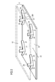
- FIG. 4 an alternative embodiment of the fluid 21 can be seen, which is basically of the fluid 21 according to FIG. 2 and FIG. 3 differ.
- the essential difference here is that the fluid 21 has no projections but depressions 29.
- Such depressions 29 are known, for example, from the sport of golf. Golf balls have comparatively similar depressions 29.
- Such recesses 29, which may also be referred to as dimples, lead to turbulence of the cooling medium flowing out of the flow direction 22. This turbulence leads to improved heat transfer to the cooling wall. The result is that a more effective cooling of the rotor 1 is possible.
Landscapes
- Engineering & Computer Science (AREA)
- Power Engineering (AREA)
- Motor Or Generator Cooling System (AREA)
Priority Applications (1)
| Application Number | Priority Date | Filing Date | Title |
|---|---|---|---|
| EP08007796A EP2112746A1 (fr) | 2008-04-22 | 2008-04-22 | Machine dynamoélectrique |
Applications Claiming Priority (1)
| Application Number | Priority Date | Filing Date | Title |
|---|---|---|---|
| EP08007796A EP2112746A1 (fr) | 2008-04-22 | 2008-04-22 | Machine dynamoélectrique |
Publications (1)
| Publication Number | Publication Date |
|---|---|
| EP2112746A1 true EP2112746A1 (fr) | 2009-10-28 |
Family
ID=39682548
Family Applications (1)
| Application Number | Title | Priority Date | Filing Date |
|---|---|---|---|
| EP08007796A Withdrawn EP2112746A1 (fr) | 2008-04-22 | 2008-04-22 | Machine dynamoélectrique |
Country Status (1)
| Country | Link |
|---|---|
| EP (1) | EP2112746A1 (fr) |
Cited By (4)
| Publication number | Priority date | Publication date | Assignee | Title |
|---|---|---|---|---|
| CN106537733A (zh) * | 2014-07-25 | 2017-03-22 | 三菱电机株式会社 | 旋转电机 |
| WO2020064802A1 (fr) * | 2018-09-27 | 2020-04-02 | Siemens Aktiengesellschaft | Élément de blocage pour des têtes bobinées de rotor dans des turbogénérateurs avec un capot de tête de rotor ayant des forages de ventilation |
| EP3681016A1 (fr) | 2019-01-11 | 2020-07-15 | General Electric Company | Rotor de générateur et un élément de blocage d'enroulement d'extrémité d'un turbogénérateur |
| EP4447269A1 (fr) * | 2023-04-14 | 2024-10-16 | Wobben Properties GmbH | Agencement de bobine pour une machine électrique, stator, machine électrique et éolienne |
Citations (4)
| Publication number | Priority date | Publication date | Assignee | Title |
|---|---|---|---|---|
| JPH0775272A (ja) * | 1993-06-24 | 1995-03-17 | Fuji Electric Co Ltd | 回転電機の回転子巻線頭部冷却構造 |
| EP0893871A2 (fr) * | 1997-07-25 | 1999-01-27 | General Electric Company | Noyau d'une machine dynamoélectrique à refroidissement direct, avec capacité de transfert de chaleur amelioré |
| US20020074870A1 (en) * | 2000-12-19 | 2002-06-20 | Vandervort Christian Lee | Generator endwinding cooling enhancement |
| US20020074874A1 (en) * | 2000-12-20 | 2002-06-20 | Wei Tong | Heat transfer enhancement at generator stator core space blocks |
-
2008
- 2008-04-22 EP EP08007796A patent/EP2112746A1/fr not_active Withdrawn
Patent Citations (4)
| Publication number | Priority date | Publication date | Assignee | Title |
|---|---|---|---|---|
| JPH0775272A (ja) * | 1993-06-24 | 1995-03-17 | Fuji Electric Co Ltd | 回転電機の回転子巻線頭部冷却構造 |
| EP0893871A2 (fr) * | 1997-07-25 | 1999-01-27 | General Electric Company | Noyau d'une machine dynamoélectrique à refroidissement direct, avec capacité de transfert de chaleur amelioré |
| US20020074870A1 (en) * | 2000-12-19 | 2002-06-20 | Vandervort Christian Lee | Generator endwinding cooling enhancement |
| US20020074874A1 (en) * | 2000-12-20 | 2002-06-20 | Wei Tong | Heat transfer enhancement at generator stator core space blocks |
Cited By (7)
| Publication number | Priority date | Publication date | Assignee | Title |
|---|---|---|---|---|
| CN106537733A (zh) * | 2014-07-25 | 2017-03-22 | 三菱电机株式会社 | 旋转电机 |
| EP3174180A4 (fr) * | 2014-07-25 | 2018-01-17 | Mitsubishi Electric Corporation | Machine électrique rotative |
| US10418872B2 (en) | 2014-07-25 | 2019-09-17 | Mitsubishi Electric Corporation | Rotary electric machine |
| WO2020064802A1 (fr) * | 2018-09-27 | 2020-04-02 | Siemens Aktiengesellschaft | Élément de blocage pour des têtes bobinées de rotor dans des turbogénérateurs avec un capot de tête de rotor ayant des forages de ventilation |
| US11876418B2 (en) | 2018-09-27 | 2024-01-16 | Siemens Energy Global GmbH & Co. KG | Blocking element for rotor winding heads on turbogenerators with rotor cap with radial ventilation bores |
| EP3681016A1 (fr) | 2019-01-11 | 2020-07-15 | General Electric Company | Rotor de générateur et un élément de blocage d'enroulement d'extrémité d'un turbogénérateur |
| EP4447269A1 (fr) * | 2023-04-14 | 2024-10-16 | Wobben Properties GmbH | Agencement de bobine pour une machine électrique, stator, machine électrique et éolienne |
Similar Documents
| Publication | Publication Date | Title |
|---|---|---|
| EP1543603B1 (fr) | Machine electrique comprenant un stator a demi-bobines refroidies | |
| CH323433A (de) | Verfahren und Einrichtung zum Kühlen von elektrischen Leitern einer ganz gekapselten, dynamoelektrischen Maschine | |
| WO2011154205A2 (fr) | Machine dynamoélectrique équipée d'un système de refroidissement d'air/de liquides | |
| WO2011048038A2 (fr) | Générateur | |
| DE2608291A1 (de) | Gasgekuehlter generator-rotor mit erhoehter ventilation | |
| DE19919040C2 (de) | Synchronmaschine oder Asychronmaschine für große Windenergieanlagen | |
| EP4193450A1 (fr) | Éolienne ayant au moins une machine dynamo-électrique | |
| DE102012204197A1 (de) | Elektrische Maschine mit Phasentrenner | |
| EP2112746A1 (fr) | Machine dynamoélectrique | |
| EP2804291A1 (fr) | Carter pour un moteur électrique | |
| EP1204193B1 (fr) | Système de refroidissement d'une machine électrique tournante à faible inertie | |
| CH611087A5 (en) | Electrical non-salient pole synchronous generator with gas cooling | |
| EP2112745A1 (fr) | Procédé de refroidissement d'un conducteur électrique | |
| DE102019111931A1 (de) | Elektrische Maschine mit von einem externen Kühlmedium direkt durchströmbaren Läuferstäben | |
| EP2975729A1 (fr) | Générateur d'éolienne | |
| DE102015200159A1 (de) | Rotierende elektrische Maschine mit Permanentmagneten | |
| DE102018126320A1 (de) | Rotor für eine elektrische Maschine und elektrische Maschine | |
| EP2693608A1 (fr) | Bobine pour une machine électrique | |
| DE69932309T2 (de) | Zwangskonvektions-Kühlangordnung für rotierende elektrische Maschinen | |
| WO2023046332A1 (fr) | Rotor pour une machine électrique tournante, machine électrique tournante, entraînement de capsule et embarcation nautique | |
| DE102021210756A1 (de) | Rotor für eine elektrische rotierende Maschine, elektrische rotierende Maschine, Gondelantrieb und Wasserfahrzeug | |
| DE2403226A1 (de) | Dynamoelektrische maschine mit staender und laeufer | |
| EP1032113A1 (fr) | Dispositif de refroidissement pour une machine électrique, notamment pour une machine à champ tournant | |
| DE19810628A1 (de) | Belüftungssystem für die Erregerwicklung großer Schenkelpolmaschinen | |
| EP2847850B1 (fr) | Bobine pour une machine électrique |
Legal Events
| Date | Code | Title | Description |
|---|---|---|---|
| PUAI | Public reference made under article 153(3) epc to a published international application that has entered the european phase |
Free format text: ORIGINAL CODE: 0009012 |
|
| AK | Designated contracting states |
Kind code of ref document: A1 Designated state(s): AT BE BG CH CY CZ DE DK EE ES FI FR GB GR HR HU IE IS IT LI LT LU LV MC MT NL NO PL PT RO SE SI SK TR |
|
| AX | Request for extension of the european patent |
Extension state: AL BA MK RS |
|
| 17P | Request for examination filed |
Effective date: 20100426 |
|
| 17Q | First examination report despatched |
Effective date: 20100525 |
|
| AKX | Designation fees paid |
Designated state(s): AT BE BG CH CY CZ DE DK EE ES FI FR GB GR HR HU IE IS IT LI LT LU LV MC MT NL NO PL PT RO SE SI SK TR |
|
| RAP1 | Party data changed (applicant data changed or rights of an application transferred) |
Owner name: SIEMENS AKTIENGESELLSCHAFT |
|
| STAA | Information on the status of an ep patent application or granted ep patent |
Free format text: STATUS: THE APPLICATION IS DEEMED TO BE WITHDRAWN |
|
| 18D | Application deemed to be withdrawn |
Effective date: 20170314 |