EP2112761A2 - Système de génération d'électricité - Google Patents
Système de génération d'électricité Download PDFInfo
- Publication number
- EP2112761A2 EP2112761A2 EP09075184A EP09075184A EP2112761A2 EP 2112761 A2 EP2112761 A2 EP 2112761A2 EP 09075184 A EP09075184 A EP 09075184A EP 09075184 A EP09075184 A EP 09075184A EP 2112761 A2 EP2112761 A2 EP 2112761A2
- Authority
- EP
- European Patent Office
- Prior art keywords
- generator
- engine
- controller
- power
- electrical
- Prior art date
- Legal status (The legal status is an assumption and is not a legal conclusion. Google has not performed a legal analysis and makes no representation as to the accuracy of the status listed.)
- Withdrawn
Links
Images




Classifications
-
- B—PERFORMING OPERATIONS; TRANSPORTING
- B60—VEHICLES IN GENERAL
- B60L—PROPULSION OF ELECTRICALLY-PROPELLED VEHICLES; SUPPLYING ELECTRIC POWER FOR AUXILIARY EQUIPMENT OF ELECTRICALLY-PROPELLED VEHICLES; ELECTRODYNAMIC BRAKE SYSTEMS FOR VEHICLES IN GENERAL; MAGNETIC SUSPENSION OR LEVITATION FOR VEHICLES; MONITORING OPERATING VARIABLES OF ELECTRICALLY-PROPELLED VEHICLES; ELECTRIC SAFETY DEVICES FOR ELECTRICALLY-PROPELLED VEHICLES
- B60L15/00—Methods, circuits, or devices for controlling the traction-motor speed of electrically-propelled vehicles
- B60L15/20—Methods, circuits, or devices for controlling the traction-motor speed of electrically-propelled vehicles for control of the vehicle or its driving motor to achieve a desired performance, e.g. speed, torque, programmed variation of speed
- B60L15/2045—Methods, circuits, or devices for controlling the traction-motor speed of electrically-propelled vehicles for control of the vehicle or its driving motor to achieve a desired performance, e.g. speed, torque, programmed variation of speed for optimising the use of energy
-
- H—ELECTRICITY
- H02—GENERATION; CONVERSION OR DISTRIBUTION OF ELECTRIC POWER
- H02P—CONTROL OR REGULATION OF ELECTRIC MOTORS, ELECTRIC GENERATORS OR DYNAMO-ELECTRIC CONVERTERS; CONTROLLING TRANSFORMERS, REACTORS OR CHOKE COILS
- H02P9/00—Arrangements for controlling electric generators for the purpose of obtaining a desired output
- H02P9/04—Control effected upon non-electric prime mover and dependent upon electric output value of the generator
-
- H—ELECTRICITY
- H02—GENERATION; CONVERSION OR DISTRIBUTION OF ELECTRIC POWER
- H02P—CONTROL OR REGULATION OF ELECTRIC MOTORS, ELECTRIC GENERATORS OR DYNAMO-ELECTRIC CONVERTERS; CONTROLLING TRANSFORMERS, REACTORS OR CHOKE COILS
- H02P2101/00—Special adaptation of control arrangements for generators
- H02P2101/45—Special adaptation of control arrangements for generators for motor vehicles, e.g. car alternators
-
- Y—GENERAL TAGGING OF NEW TECHNOLOGICAL DEVELOPMENTS; GENERAL TAGGING OF CROSS-SECTIONAL TECHNOLOGIES SPANNING OVER SEVERAL SECTIONS OF THE IPC; TECHNICAL SUBJECTS COVERED BY FORMER USPC CROSS-REFERENCE ART COLLECTIONS [XRACs] AND DIGESTS
- Y02—TECHNOLOGIES OR APPLICATIONS FOR MITIGATION OR ADAPTATION AGAINST CLIMATE CHANGE
- Y02T—CLIMATE CHANGE MITIGATION TECHNOLOGIES RELATED TO TRANSPORTATION
- Y02T10/00—Road transport of goods or passengers
- Y02T10/60—Other road transportation technologies with climate change mitigation effect
- Y02T10/64—Electric machine technologies in electromobility
-
- Y—GENERAL TAGGING OF NEW TECHNOLOGICAL DEVELOPMENTS; GENERAL TAGGING OF CROSS-SECTIONAL TECHNOLOGIES SPANNING OVER SEVERAL SECTIONS OF THE IPC; TECHNICAL SUBJECTS COVERED BY FORMER USPC CROSS-REFERENCE ART COLLECTIONS [XRACs] AND DIGESTS
- Y02—TECHNOLOGIES OR APPLICATIONS FOR MITIGATION OR ADAPTATION AGAINST CLIMATE CHANGE
- Y02T—CLIMATE CHANGE MITIGATION TECHNOLOGIES RELATED TO TRANSPORTATION
- Y02T10/00—Road transport of goods or passengers
- Y02T10/60—Other road transportation technologies with climate change mitigation effect
- Y02T10/72—Electric energy management in electromobility
Definitions
- the present application relates to a power generation system.
- the disclosed power generation system may include, for example, diesel generators for supplying various AC and DC loads.
- a generator set (or engine-generator set, genset, generator, etc.) is a combination of an electrical generator and an engine that may be mounted together to form a single piece of equipment or separate pieces of equipment electrically coupled together.
- Generator sets can produce direct current or alternating current and may be either single-phase or three-phase.
- Generator sets are often used in power generation systems to supply electrical power to systems where utility power may not be readily available or in situations where power is only needed temporarily.
- generator sets may be used to supply power tools, mobile lighting, amusement rides, vehicle propulsion power electronics, marine propulsion power and electronics, etc.
- the engine is adjusted to maintain a substantially constant voltage to a power distribution bus.
- These conventional systems do not account for efficiency gains that could be achieved for the overall system efficiency by adjusting the engine without considering the voltage being supplied by the generator.
- Certain conventional systems adjust the engine speed based on a given load condition, but such an adjustment is based solely on the efficiency of the engine and not a combined efficiency including other components of the system.
- a power generation system includes an engine and an electrical generator driven to rotate at rotational speed by the engine.
- the generator is configured to supply an adjustable amount of required electrical power having a voltage and a current to at least one electrical load.
- the system also includes a controller configured to adjust at least one operating parameter of the engine in order to maximize efficiency of the system.
- the system efficiency is a measure of the combined operation of generator and engine and load, wherein each of the generator, engine and load has different loss characteristics and wherein system efficiency is measure of combined efficiency for a given load condition.
- the controller is configured to maximize system efficiency based only upon the required electrical power being supplied by the generator.
- the controller is configured so that the controller does not independently consider any one of the rotational speed, the voltage or the current being supplied by the generator when adjusting the at least one operating parameter.
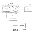
- Fig. 1 is a schematic of a control system and generator set coupled to an electrical load, according to an exemplary embodiment
- Fig. 2 is a schematic of a control system and generator sets coupled to a plurality of electrical loads, according to an exemplary embodiment
- Fig. 3 is a schematic of a control system and generator set with the electrical load including a motor and motor controller, according to an exemplary embodiment
- Fig. 4 is a schematic of a control system and generator set with an inverter electrically coupled to the generator set and load, according to an exemplary embodiment
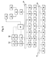
- Fig. 5 is a schematic of a power generation system, according to an exemplary embodiment.
- Fig. 6 is a schematic of a power generation system, according to an exemplary embodiment.
- Fig. 7 is a schematic of a power generation system for a marine vessel, according to an exemplary embodiment.
- Fig. 8 is a schematic of a power generation system for a marine vessel, according to an exemplary embodiment.
- a representative power generation system includes a generator set 14 that is configured to provide electrical power to a load 200 based on signals received from a controller 110 and one or more sensors 120.
- the generator set 140 may include an electrical generator 16 and an engine 18.
- the electrical generator 160 and engine 180 may be integrally mounted, while in another exemplary embodiment, the electrical generator 160 and engine 180 may be separate and only electrically coupled.
- the engine 180 e.g., a diesel engine, a gasoline engine, etc.
- the engine 180 typically provides mechanical power and motion to the electrical generator 160.
- the engine 180 is a reciprocating internal combustion engine.
- the electrical generator 160 e.g., a variable speed generator
- this electrical power may be either direct current (DC) or alternating current (AC).
- the generator 160 is configured to supply an adjustable amount of required electrical power having a voltage and a current to the electrical load 200.
- the controller 110 is configured to adjust at least one operating parameter of the engine 180 in order to maximize efficiency of the system.
- the system efficiency is a measure of the combined operation of generator 160, engine 180 and load 200.
- Each of the generator 160, engine 180 and load 200 has different loss characteristics and the system efficiency is measure of the combined efficiency for a given load condition.
- the controller 110 is configured to maximize system efficiency based only upon the required electrical power being supplied by the generator.
- the controller 110 is configured so that the controller does not independently consider any one of the rotational speed, the voltage or the current being supplied by the generator when adjusting the at least one operating parameter.
- the load 200 may be any electrical load that provides impedance or resistance to the system. According to exemplary embodiments, the load 200 may be a motor, a lighting system, a battery, or any other electrically powered load.
- the sensors 120 may be configured to sense one or more conditions related to the generator set 140 or the load 200 and to communicate the sensed condition to the controller 100. According to one exemplary embodiment, the sensors 120 may sense a voltage drop across the load 200. According to another exemplary embodiment, the sensors 120 may sense a load characteristic of the load 200, for example a load resistance or impedance, a power consumption, an efficiency metric, or any other metric or combination thereof related to the load 200. According to still another exemplary embodiment, the sensors 120 may sense the current flowing through the load 200. According to other exemplary embodiments, the sensors 120 may sense any characteristic related to the generator set 140 and/or the load 200. For example, the sensors 120 may be configured to sense the various operating conditions of the engine such as temperature, fuel level, exhaust conditions, speed, etc. There may be multiple sensors 120 provided in order to provide for sensing more than one of the aforementioned conditions simultaneously.
- the controller 110 is configured to the control engine 180 of the generator set 140 based on inputs from the sensors 120. According to various exemplary embodiments, the controller 110 may control the engine speed, airflow, fuel flow, engine timing, or any other controllable function of the engine 180. For example, if the engine includes a turbocharger, the controller 110 may operate to adjust the position of the turbocharger in order to adjust the speed of the engine. For example, based on a voltage drop across the load 200, the controller 110 may increase the speed of the engine 180 to maintain relatively consistent power across the load 200. According to another exemplary embodiment, the controller 110 may control the engine 180 by referencing a set of stored values, for example in a look-up table. According to other exemplary embodiments, the controller 110 may control the engine 180 by a set of digital logic, analog circuitry, software programming, or any combination thereof.
- the controller 110 is configured to control the engine to maximize the efficiency of the overall system taking into account the combined efficiencies of the engine, generator and the load.
- the controller 110 may determine the combined system efficiency by referencing a set of stored values, for example in a look-up table.
- the stored values may be representative of each system component (e.g., loads, generator(s), engine(s))
- the controller 110 may control the engine 180 by a set of digital logic, analog circuitry, software programming, or any combination thereof, wherein the logic, circuitry or programming is configured to calculate an appropriate adjustment to an engine parameter (e.g., throttle position, fuel input, air intake, turbocharger position, rpm, etc.) in order to maximize the efficiency of the system.
- the system efficiency may be weighted more heavily to one component of the system such as, for example, the load or generator depending on certain additional parameters such as, for example, the remaining operating life of the particular component.
- Fig. 2 discloses an alternative embodiment which includes multiple generator sets 214 coupled to multiple electrical loads 220, 222.
- the generator sets are controlled by a system controller 210.
- an engine 218 and a generator 216 are coupled together to form the generator set 214, which supplies the first load 220 and second load 222.
- the first load 220 and/or the second load 220 may be a motor, an RC network, digital logic, or any other load capable of being electrically coupled to the generator sets 214.
- the engines 218 may have variations in design, which may cause some engines 218 to operate more efficiently at one speed/load condition than another using system parameter fluctuations (e.g., load, speed, voltage, etc.).
- the design of the engine 218 may result in relatively flat efficiency curve. For example, a system may have an efficiency of 61 % based on the generator 216 and the engine 218 interaction, therefore, for every 100 hp of installed power on the system, only 61 hp of output power would be achieved.
- the engine 218 may have a 98% efficiency factor and the generator 216 a 97% efficiency factor, yielding the generator set 214 with a 95% efficiency factor.
- the system controller 210 may be configured to conserve energy by modifying the output of the generator set 214 and, thus, may improve the efficiency of other parts of the system.
- the electrical losses from the generator set 214 are relatively low, which allows the system to be more fuel efficient because the losses are less than the inherent limitations of a direct drive system.
- the system controller 210 efficiently utilizes the engine 212 and the load 220, 222 to gain system efficiencies that may offset the electrical conversion losses.
- the components may interact to achieve a high system efficiency and maintain that efficiency over a wide range of speeds and the loads.
- the load 200 may be a direct-drive propulsion motor that does not incur significant loss (i.e. 3 to 5 percent loss typical of transmissions and gear reducers) and the electrical generator 160 may be a variable-speed generator that allows the speed and power output of the engine 180 to closely match the loads that are placed on the electrical generator 160.
- a ten percent fuel savings may be achieved by allowing the speed of the engine 180 to fluctuate with the loads, thereby reducing inefficiencies associated with intermittent high-speed, low-load operation.
- a ten percent fuel savings can be achieved by using a larger and more efficient load (e.g., a larger and more efficient propeller).
- a thirteen percent savings may be achieved by more closely aligning the power required by the load 200 and the power produced by the engine 180 and, by doing so, shifting the load of the engine 180 to a more optimum point on its power curve over a wide range of speeds and conditions.
- an additional savings of twenty percent may be achieved under some load conditions if multiple generators 160 are installed. These demonstrated fuel savings totaling 30 to 50 percent may be more than the losses introduced by the system.
- controllers 110, 120 The operating characteristics of the controllers 110, 120 described above, apply fully to the controllers 500 described below during the operation of the systems described in Figs. 5-8 .
- Fig. 5 discloses another embodiment of a power generation system including a system controller 500 and a pair of generator sets 510, 520 for supplying electrical power to various loads.
- the system may include a power distribution system including, for example, an AC bus 575 and a DC bus 576.
- the AC bus is a 120 V AC bus that supplies typical AC loads 585 such as, for example, personal convenience items like television, stereo, microwave, hair dryer, appliances, etc.
- the DC Bus 576 may be a 240 V DC bus and may supply DC loads such as large appliances or the like such as stove, oven, water heater, etc.
- the various DC loads 586 may be protected by a protection circuit 588 and/or breaker system.
- the DC bus loads may also include, for example, a marine propulsion motor 565 or motors (e.g., port and starboard motors).
- the propulsion motor 565 may be configured as a permanent magnet brushless DC motor. In one example, the motor 565 is rated for 35 HP at 1200 RPM.
- the propulsion motor may be connected to the DC bus 576 via a inverter 566, which may preferably be configured and referred to as a brushless DC motor controller.
- Other DC loads may include a variable speed DC motor 567 supplying for example an HVAC system.
- Other DC loads may include another permanent magnet brushless DC motor 568 connected to the DC bus 576 via an inverter 569.
- the inverter 569 may be a brushless DC motor controller.
- the generator sets 510, 520 may be connected separately or in combination (via switches or breakers) to the AC bus.
- the example shown in Fig. 5 includes two generator sets, but the system may include one or more generator sets.
- Each generator set includes a prime mover or engine 511, 521 for driving the generator 512, 522.
- the generator set may include a synchronous generator and a diesel engine.
- two generators may be driving by a single engine.
- a common generator head may be mechanically coupled to the engine.
- the generator would include two sets of windings and two controllers; one for each generator.
- one generator would produce voltage in the range of 400 to 800 V DC for an approximately 600 V DC bus. This high voltage bus could supply larger loads such as, for example, a propulsion motor or hydraulic pumps.
- the second generator would produce voltage in the range of 150 to 300 V DC for a 240 V DC bus and would supply loads such as appliances, lights and a secondary AC bus.
- the generator may be a permanent magnet generator including a rotor driven by the crankshaft of the corresponding diesel engine.
- the permanent magnets for generator excitation may be carried on the rotor, and the stator may be arranged within the rotor and carry the rotor windings for the generator. Alternatively, the stator windings may be arranged to surround the rotor.
- the generator may employ numerous thin laminations or relatively few thicker laminations.
- the diesel engine is used for power generation and may be operated to control various engine parameters such as emissions and fuel efficiency. Also, the engine may be operated to maintain power overhead required to react to instantaneously applied load increases or step load requirements such as, for example, rapid increase in propulsion requirements.
- the present invention includes adjusting the engine speed so that the engine operates in the proper band of the associated power curve. Also, according to another embodiment a portion of the loading may be temporarily dropped or reduced to allow the engine speed to increase and respond to the overall increased demand.
- the engine may include, for example, any variable speed diesel or internal combustion engines, Stirling engines, gas turbines and micro-turbines.
- the power generation system may include a passive or active rectification system(s) or circuit(s) 580, 581.
- the active rectification circuit 580 may be referred to as a active rectifier and, in one alternative embodiment, may be integrated into the generator.
- the active rectification circuit includes active elements such as power MOSFETs or other high end FETs. The FETs are switched on and off to rectify the generator output. In one example, the FETs are turned on and off in a manner corresponding to the frequency of the stator phases in order to achieve active synchronous rectification. Active rectification will allow the bus voltage to be independent of engine and generator speed. As a result, for example, at low engine speeds the bus voltage can be increased to reduce energy losses and increase power output.
- the active rectifier includes a suitable programmable circuit of active switch elements.
- the power generation system may include a rectifier/inverter unit 570 for transferring power between the AC and DC busses (see Fig. 6 , for example).
- a rectifier/inverter unit 570 for transferring power between the AC and DC busses (see Fig. 6 , for example).
- a battery charging unit 535 may also be provided.
- the auxiliary battery may also provide power to an auxiliary DC bus 577, typically low voltage (e.g., 12 V DC).
- the auxiliary DC bus 577 supplies power to low voltage DC loads 580 such as, for example, lighting, communication equipment, appliances, etc.
- the system may include a motor generator set for converting DC power into AC power or vice versa.
- Alternative sources of DC power may also be provided such as, for example, a flywheel generator, photovoltaic devices and fuel cells.
- the battery 530 may be used to regulate load on the system an to optimize overall system efficiency.
- the controller 500 may adjust the batter charging device 535 to discharge or charge the battery 530 in order to add additional load or lighten the load on the generator(s) 512, 522 for overall system efficiency.
- the battery 530 may also be used as a storage device for storing electrical power.
- the power generation system may also include alternative sources of power such as, for example, a flywheel generator or a micro-turbine generator.
- the alternative generator 590 may be placed on the AC bus 575 or, as shown in Fig. 5 , on the DC Bus 576 via a transformer 591 and rectifier 592 system.
- One or more alternative generators 590 or power supplies may be provided.
- the alternative power may be a shore based power supply.
- the flywheel devices mentioned above may be used to convert natural energy such as, for example, the force of water, to generate stored energy.
- natural energy such as, for example, the force of water
- the conversion of natural energy may be especially useful in a marine environment where back up utility power is unavailable.
- Fig. 6 discloses an alternative power generation system including a single generator set 510.
- the system disclosed in Fig. 6 is similar in most respects to the system disclosed in Fig. 5 .
- a battery 530 is provided to supply power to a low voltage DC bus 577 via a converter 535.
- a DC to AC inverter 570 is provided for converting the generated DC power on the DC bus 576 to the AC bus 575.
- Figs. 7 and 8 disclose two examples of a power generation system for a marine vessel.
- the components of theses systems are labeled and include exemplary component ratings.
- Figs. 7 and 8 show exemplary systems that may be configured and operated in accordance with the features shown in described with regard to Figs. 1-6 .
- the systems shown in Figs. 7 and 8 are exemplary only.
- the present application and claims are not limited to shipboard power systems or to power generation systems for a marine environment.
- the systems and concepts disclosed and claimed herein are applicable to engine driven power generation systems generally as disclosed and claimed herein.
- the power generation system includes a system controller 500 to control the operation of the various components and devices in the power generation system. Although shown in the various figures of the application as a single controller 500, the system controller may be separated or integrated into one or many different microprocessor based controllers.
- the system controller 500 may be configured to adjust at least one operating parameter of the engine in order to maximize efficiency of the system based only upon the required electrical power being supplied by the generator. For example, according to one embodiment the controller is configured to adjust engine speed in order maximize efficiency of the system. In another embodiment, the controller is configured to adjust the fuel input to the engine in order to maximize efficiency of the system.
- Each engine 511, 521 may include a turbocharger and the controller 500 may be configured to adjust a position of the turbocharger in order to maximize efficiency of the system.
- the controller 500 may be configured to receive inputs from various sensors when the load on the system is changing.
- the controller may receive inputs on breaker or switch position or throttle position for a propulsion motor.
- the controller can be configured to receive inputs from various voltage and current sensors so that the power being drawn by various loads may be detected.
- the controller receives information that the amount or rate of load change is greater than a predetermined amount the speed of the engine could be adjusted.
- the controller can communicate and control the loads directly so that the amount or rate of the load change is limited in certain situations. For example, in the case of an electric motor the rate of change of motor speed could be limited by the system controller.
- the controller 500 may be controller is configured to operate during power changes so that before the required electrical power changes to a new level the controller adjusts an operating parameter of the engine(s) 511, 521 in order to maximize efficiency of the system at the new power level.
- the controller 500 is configured to receive a signal providing information from the load regarding the required power level.
- the controller 500 may be configured to receive a signal providing information regarding the required power level from a user interface 600.
- the system may include a power converter or rectifier 580 for conditioning the electrical power produced by the generator to supply the required electrical power.
- the power converter 580 is configured to adjust characteristics of the electrical power based on the required electrical power and wherein the controller 500 is further configured to maximize system efficiency based on an additional input received from the power converter.
- the first generator set 510 may be configured to produce a voltage in the range of 540 to 660 volts (preferably around 600 V), and the second generator set may be configured to produce a voltage in the rage of 200 to 280 volts (preferably around 240 V).
- the two generator sets may supply high and low voltage power distribution busses, respectively.
- the controller may be configured to adjust, for example, the follow operating parameters: generator RPM; generator voltage; and engine RPM. Also, for certain engine systems, the controller may adjust the injection timing, injection duration or number of injections; or the engine's turbo boost.
- the controller may also control the battery 530 to control the amount of electrical power being transferred to/or from the battery system in order to optimize the combined performance of the engine and generator. For example, bus voltages may be adjusted to control the rate of battery charge or discharge. The battery discharge may be adjusted to control the capacity of the engine.
- the alternative generator systems e.g., the flywheel generator
- the controller may also control the load sharing between two or more generators.
- the system may be configured to operate the generators at different conditions. For example, if three generators are provided, an operator's desire for maximum fuel efficiency may dictate operating the generators at 80, 20 and 0 percent capacity, respectively. Alternatively, for maximizing generator life each generator may be operated at 33 percent capacity. If an operator desires faster throttle response (e.g., when the system is supplying a propulsion motor and quick maneuverability is desired) each generator set may be operated in the power band at maximum power capacity.
- the system controller may also operate in conjunction with the active rectifier 580 described above.
- the system controller may control the rectifier to make engine speed independent of the AC bus voltage.
- the system controller can control the rectifier circuit to set a system voltage without regard to the speed of the engine.
- Conventional systems only suggest the use of active rectification to stabilize the voltage output.
- the present application discloses employing active rectification to adjust and controller the voltage independent of generator speed. As a result, the system control can control the system to improve both the fuel efficiency of the engine and the electrical efficiency of the loads on the system. Some loads may operate more efficiently at a bus voltage different from the output voltage produced for a given fuel efficient engine speed.
- the controller may be configured to operate in one of a number of selected configurations. For example, a system operate may select a "fuel efficiency" configuration or a "throttle response" configuration. Thus, the controller may automatically adjust the various system components and parameters (e.g., generator voltage) to optimize the performance of the generator, engine and system loads (e.g., a motor) in accordance with the operator selected configuration.
- system components and parameters e.g., generator voltage
- engine and system loads e.g., a motor
- the system may include a standard user interface (e.g., keyboard, touch screen , etc.) 600 for inputting a load command (e.g., main engine(s) or propulsion motor(s) speed) and a desired system operating characteristic.
- the system controller may be configured to receive the speed command and desired operating characteristic from the user interface and to subsequently determine a required power to be supplied to the propulsion motor and an optimum generator RPM for satisfying the desired operating characteristic.
- the controller may be configured to control the engine to optimize certain engine parameters for the optimum RPM and power requirement; and wherein the controller adjusts the voltage of the power distribution system to minimize energy loses from the system.
- the system controller 500 may be configured as above, with regard to Figs. 2 , to control the various components of the system. Also, software implementation of the above described features could be accomplished with standard programming techniques with rule-based logic and other logic to accomplish the various functions and processes of the controller(s).
- a power generation system including an engine 511 and an electrical generator 521 driven to rotate at a rotational speed by the engine.
- the generator 521 is configured to supply an adjustable amount of required electrical power having a voltage and a current to a propulsion motor 568.
- the controller 500 may be configured to adjust at least one operating parameter of the engine 511 in order to maximize efficiency of the system based only upon the required electrical power being supplied by the generator 521.
- the controller 500 does not independently consider any one of the rotational speed, the voltage or the current being supplied by the generator 521 when adjusting the at least one operating parameter.
- the controller 500 may be configured to adjust engine speed and/or fuel input to the engine 511 in order maximize efficiency of the system. If the engine 511 includes a turbocharger the controller 500 may be configured to adjust a position of the turbocharger in order to maximize efficiency of the system. The controller 500 may be configured to operate during power changes so that before the required electrical power changes to a new level the controller 500 adjusts the at least one operating parameter in order to maximize efficiency of the system at the new power level.
- the controller 500 can receive a signal (e.g., from a sensor 120) providing information from the load regarding the required power level. Alternatively, the controller 500 may receive a signal providing information regarding the required power level from a user interface 600.
- the user interface 600 may be an engine speed controller or throttle adjustment mechanism.
- the system may include a power converter (e.g., inverters/rectifiers 569, 570, 580) for conditioning the electrical power produced by the generator 521 to supply the required electrical power to at least one load (e.g., the propulsion motor 570).
- the power converter 569, 570, 580 adjusts characteristics of the electrical power based on the electrical power required by the at least one load.
- the controller 500 may be configured to maximize system efficiency based on an additional input received from the power converter 569, 570.
- the system controller 500 may also be configured to control the various loads on the power generation system.
- a generator set 314 is controlled by a controller 310 and supplies electrical power to a load 320, similar to the system of Fig. 1 .
- the load 320 includes a motor 330 and a motor controller 340.
- the motor 330 is configured to convert electrical power received from the generator set 314 into mechanical power. According to various exemplary embodiments, the motor 330 may receive direct current (DC) or alternating current (AC) and may be any electrically powered motor of past, present, or future design.
- DC direct current
- AC alternating current
- the motor controller 340 is configured to monitor and adjust, if necessary, the current traveling to the motor 330.
- the motor controller 340 may clip the current to a predetermined maximum/minimum threshold value if the amplitude is too great for the motor 330 to handle.
- the motor controller 340 may scale the AC sinusoid to an acceptable level (e.g., using an amplifier, resistor, etc. if the amplitude is too great for the motor 330 to handle.
- the motor controller 340 may adjust the level of the direct current to a more optimal level.
- the motor controller 340 may control whether current reaches the motor 330 or not, effectively turning the motor 330 on or off. Operation of the motor controller may be dynamically controlled by the system controller 310 so that operation of both the generator and the load (e.g. motor) may be optimized.
- a generator set 414 is controlled by a controller 410 and supplies electrical power to a load 420, similar to the system in Fig. 1 .
- the current is adjusted by an inverter 450.
- the load 420 is similar to the load 20 and may be a propeller, a drive wheel, a fan, a sound system, a lighting system, a bilge system, or any other electrically powered load.
- the inverter 450 is configured to handle voltage fluctuations from the generator set 414 and convert DC power from the generator set 414 to AC power.
- the inverter 450 may be an active rectification circuit capable of adjusting the line voltage or the voltage across the load 420.
- the engine speed of the generator set 414 may be adjusted independently of the line voltage. For example, the speed of the engine may be increased while the line voltage remains constant. In another example, the engine speed may remain constant while the line voltage is lowered. Alternatively, both the engine speed and line voltage may be adjusted.
- the inverter 450 may include a passive rectification circuit. In other exemplary embodiments, the inverter 450 may be a non-rectifying circuit of any past, present, or future design.
- circuitry of the exemplary embodiments of Figs. 3 and 4 may be used in the systems of Fig. 1 , 2 , 5 , 6 , 7 and 8 or any other generator set system.
- Any load 20, 220, 222) may include a motor and a motor controller or may be controlled by an inverter.
Landscapes
- Engineering & Computer Science (AREA)
- Power Engineering (AREA)
- Transportation (AREA)
- Mechanical Engineering (AREA)
- Control Of Eletrric Generators (AREA)
Applications Claiming Priority (1)
| Application Number | Priority Date | Filing Date | Title |
|---|---|---|---|
| US12/081,786 US20090261599A1 (en) | 2008-04-21 | 2008-04-21 | Power generation system |
Publications (1)
| Publication Number | Publication Date |
|---|---|
| EP2112761A2 true EP2112761A2 (fr) | 2009-10-28 |
Family
ID=40935546
Family Applications (1)
| Application Number | Title | Priority Date | Filing Date |
|---|---|---|---|
| EP09075184A Withdrawn EP2112761A2 (fr) | 2008-04-21 | 2009-04-21 | Système de génération d'électricité |
Country Status (2)
| Country | Link |
|---|---|
| US (1) | US20090261599A1 (fr) |
| EP (1) | EP2112761A2 (fr) |
Cited By (4)
| Publication number | Priority date | Publication date | Assignee | Title |
|---|---|---|---|---|
| EP2323239A1 (fr) * | 2009-11-13 | 2011-05-18 | Ascot S.R.L. | Station intégrée pour alimentation électrique CC de charges à distance géographiquement, des antennes de télécommunication par exemple |
| EP2828107A4 (fr) * | 2012-03-23 | 2016-04-06 | Thermo King Corp | Système de commande pour système de réfrigération de transport |
| EP3048719A1 (fr) * | 2015-01-23 | 2016-07-27 | GE Jenbacher GmbH & Co OG | Procede de fonctionnement d'un systeme comprenant une machine-outil rotative |
| EP3849036A1 (fr) * | 2020-01-07 | 2021-07-14 | Hamilton Sundstrand Corporation | Systèmes de turbine à air dynamique |
Families Citing this family (42)
| Publication number | Priority date | Publication date | Assignee | Title |
|---|---|---|---|---|
| US7831343B2 (en) * | 2006-11-03 | 2010-11-09 | Gm Global Technology Operations, Inc. | Efficiency optimized hybrid operation strategy |
| US8098054B2 (en) * | 2007-10-10 | 2012-01-17 | John Alexander Verschuur | Optimal load controller method and device |
| US20090312885A1 (en) * | 2008-06-11 | 2009-12-17 | Buiel Edward R | Management system for drilling rig power supply and storage system |
| US9725008B2 (en) * | 2008-11-10 | 2017-08-08 | Sumitomo Heavy Industries, Ltd. | Hybrid type construction machine |
| US8912672B2 (en) * | 2009-05-20 | 2014-12-16 | Cummins Power Generator IP, Inc. | Control of an engine-driven generator to address transients of an electrical power grid connected thereto |
| US8400001B2 (en) * | 2010-01-15 | 2013-03-19 | Kohler Co. | Adaptive control of an electrical generator set based on load magnitude |
| CA2800899C (fr) * | 2010-05-28 | 2020-07-07 | Nabors Drilling Technologies Usa, Inc. | Systemes et procedes de gestion de carburant d'une installation de forage |
| RU2576021C2 (ru) * | 2011-03-11 | 2016-02-27 | Сименс Акциенгезелльшафт | Возбудитель блока генерирования мощности, блок генерирования мощности и оборудование вывода энергии в электрической сети |
| US9048765B2 (en) | 2011-03-29 | 2015-06-02 | Innovus Power, Inc. | Engine powered generator |
| CN102358575B (zh) * | 2011-09-30 | 2013-10-23 | 新兴铸管股份有限公司 | 桥式起重机的电气故障查询系统 |
| US20130214602A1 (en) * | 2012-02-20 | 2013-08-22 | Engineered Electric Company | Method and system for generator control |
| US9552029B2 (en) | 2012-02-20 | 2017-01-24 | Engineered Electric Company | Micro grid power distribution unit |
| ES2586954T3 (es) * | 2012-06-07 | 2016-10-19 | Grupo Guascor S.L. | Sistema de reparto de carga |
| US8957546B2 (en) * | 2012-07-10 | 2015-02-17 | Nixon Power Services, Llc | Electrical cogeneration system and method |
| JP2015525057A (ja) * | 2012-08-16 | 2015-08-27 | ロベルト・ボッシュ・ゲゼルシャフト・ミト・ベシュレンクテル・ハフツングRobert Bosch Gmbh | エネルギー貯蔵器および制御システムを備えるdcビルディングシステム |
| US20140152007A1 (en) * | 2012-12-05 | 2014-06-05 | Deif A/S | Managing Efficiency of a Pool of Engine-Driven Electric Generators |
| US20140152006A1 (en) * | 2012-12-05 | 2014-06-05 | Deif A/S | Managing Efficiency of an Engine-Driven Electric Generator |
| US20140156099A1 (en) | 2012-12-05 | 2014-06-05 | Cummins Power Generation, Inc. | Generator power systems with active and passive rectifiers |
| US10208677B2 (en) * | 2012-12-31 | 2019-02-19 | General Electric Company | Gas turbine load control system |
| US9638101B1 (en) * | 2013-03-14 | 2017-05-02 | Tucson Embedded Systems, Inc. | System and method for automatically controlling one or multiple turbogenerators |
| US20140373534A1 (en) * | 2013-06-21 | 2014-12-25 | Caterpillar Inc. | Energy recovery system for machine with cylinder activation and deactivation system |
| WO2015057197A1 (fr) * | 2013-10-15 | 2015-04-23 | Halliburton Energy Services, Inc. | Optimisation de consommation de carburant dans un équipement utilisé dans des opérations de site de puits |
| AT514811B1 (de) * | 2013-10-30 | 2015-04-15 | Ge Jenbacher Gmbh & Co Og | Verfahren zum Betreiben einer mit einem elektrischen Generator, insbesondere Synchrongenerator, verbundenen Brennkraftmaschine |
| AT515058B1 (de) * | 2013-10-30 | 2017-03-15 | Ge Jenbacher Gmbh & Co Og | Verfahren zum Betreiben eines mit einem Energieversorgungsnetz verbundenen Generators |
| US20150288315A1 (en) * | 2014-04-02 | 2015-10-08 | Hamilton Sundstrand Corporation | Systems utiilizing a controllable voltage ac generator system |
| AT515415B1 (de) * | 2014-10-30 | 2015-09-15 | Ge Jenbacher Gmbh & Co Og | Verfahren zum Betreiben einer Brennkraftmaschine |
| US20170353037A1 (en) * | 2016-06-06 | 2017-12-07 | Caterpillar Inc. | Flexible Variable Speed Genset System |
| CA3206994A1 (fr) | 2016-09-02 | 2018-03-08 | Halliburton Energy Services, Inc. | Systemes de motorisation hybride pour operations de stimulation de puits |
| US11897591B2 (en) | 2017-01-11 | 2024-02-13 | Brunswick Corporation | PCM controlled charging system |
| US9975619B1 (en) | 2017-01-11 | 2018-05-22 | Brunswick Corporation | PCM controlled charging system |
| US10491147B2 (en) * | 2017-11-29 | 2019-11-26 | Ford Global Technologies, Llc | Dual alternator vehicle power management |
| DE102018100541B3 (de) * | 2018-01-11 | 2019-07-11 | Mtu Friedrichshafen Gmbh | Verfahren zur Steuerung und Regelung einer Brennkraftmaschine mit Generator und Asynchronmaschine, Steuer- und Regeleinrichtung für eine Brennkraftmaschine mit Generator und Asynchronmaschine sowie Brennkraftmaschine mit Generator und Asynchronmaschine |
| EP3765342B1 (fr) * | 2018-03-14 | 2026-05-06 | Cummins, Inc. | Systèmes et procédé pour optimiser le fonctionnement de moteur de groupes électrogènes |
| CN111903032A (zh) * | 2018-03-29 | 2020-11-06 | 本田技研工业株式会社 | 混合式发动机发电机的控制装置 |
| US11848592B2 (en) * | 2018-07-17 | 2023-12-19 | Illinois Tool Works Inc. | Methods and apparatus to control engine speed of a power system |
| US11015480B2 (en) * | 2018-08-21 | 2021-05-25 | General Electric Company | Feed forward load sensing for hybrid electric systems |
| CN110784139A (zh) * | 2019-10-25 | 2020-02-11 | 江苏哲博电气有限公司 | 稳压永磁发电机组 |
| EP3940912A1 (fr) * | 2020-07-17 | 2022-01-19 | Siemens Aktiengesellschaft | Système d'alimentation électrique |
| CN114033641B (zh) * | 2021-10-08 | 2022-09-13 | 南方海洋科学与工程广东省实验室(湛江) | 电动补偿装置、温差能发电系统及发电系统补偿控制方法 |
| US12540607B2 (en) | 2023-06-23 | 2026-02-03 | Halliburton Energy Services, Inc. | Hybrid drive and distributed power systems for well stimulation operations |
| WO2025196847A1 (fr) * | 2024-03-22 | 2025-09-25 | Kirloskar Oil Engines Limited | Générateur optiprime et son procédé |
| US12584450B2 (en) | 2024-06-04 | 2026-03-24 | Rv Mobile Power, Llc | Pre-excitation of genset based on one or more trigger signals |
Family Cites Families (43)
| Publication number | Priority date | Publication date | Assignee | Title |
|---|---|---|---|---|
| US3701556A (en) * | 1971-10-01 | 1972-10-31 | Aeroquip Corp | Control system for diesel locomotive |
| US3894244A (en) * | 1973-10-03 | 1975-07-08 | Ross K Hill | Power limit and control system |
| DE2941977A1 (de) * | 1979-10-17 | 1981-04-30 | Robert Bosch Gmbh, 7000 Stuttgart | Einrichtung zum optimieren von betriebskenngroessen einer brennkraftmaschine |
| US4412136A (en) * | 1981-12-15 | 1983-10-25 | The Babcock & Wilcox Company | Load control for energy converters |
| US4645940A (en) * | 1982-09-27 | 1987-02-24 | Grumman Aerospace Corporation | Interrupt-free, unregulated power supply |
| JPH0810999B2 (ja) * | 1983-06-01 | 1996-01-31 | 本田技研工業株式会社 | 車両用発電機の制御装置 |
| US4684854A (en) * | 1986-06-16 | 1987-08-04 | Dresser Industries, Inc. | Method and apparatus for adding additional D.C. motors and control thereof |
| US4967096A (en) * | 1989-01-26 | 1990-10-30 | Sundstrand Corporation | Cross-start bus configuration for a variable speed constant frequency electric power system |
| US5311063A (en) * | 1989-06-05 | 1994-05-10 | Hubler Corporation | Automatic load speed controller for engine governor |
| US5077485A (en) * | 1989-11-06 | 1991-12-31 | Sundstrand Corporation | Voltage regulator load division using real and reactive generator output power components to control the exciter |
| US5199912A (en) * | 1991-08-15 | 1993-04-06 | Newport News Shipbuilding And Dry Dock Company | Electric power system for marine vehicles |
| US5422517A (en) * | 1993-05-26 | 1995-06-06 | United Technologies Corporation | Control of electric loads during generator failure in a multi-generator system |
| GB9319130D0 (en) * | 1993-09-15 | 1993-11-03 | British Gas Plc | An electrical power generating arrangement |
| GB9319323D0 (en) * | 1993-09-17 | 1993-11-03 | British Gas Plc | An electrical power generating arrangement |
| US6018200A (en) * | 1994-09-14 | 2000-01-25 | Coleman Powermate, Inc. | Load demand throttle control for portable generator and other applications |
| JP3592767B2 (ja) * | 1994-11-09 | 2004-11-24 | 三菱電機株式会社 | エンジンの制御装置 |
| JP3248827B2 (ja) * | 1995-01-18 | 2002-01-21 | 三菱電機株式会社 | エンジン発電機の制御装置 |
| AUPN422295A0 (en) * | 1995-07-18 | 1995-08-10 | Bytecraft Research Pty. Ltd. | Control system |
| EP0903832B1 (fr) * | 1997-01-13 | 2006-12-20 | Honda Giken Kogyo Kabushiki Kaisha | Generateur pour moteur a combustion interne |
| US5982156A (en) * | 1997-04-15 | 1999-11-09 | The United States Of America As Represented By The Secretary Of The Air Force | Feed-forward control of aircraft bus dc boost converter |
| US6037672A (en) * | 1998-02-09 | 2000-03-14 | Lockheed Martin Corporation | Generator having impedance matching prime mover output capability for operation with maximized efficiency |
| US6414400B1 (en) * | 1999-02-03 | 2002-07-02 | Coleman Powermate, Inc. | Small engine driven generator |
| US6825575B1 (en) * | 1999-09-28 | 2004-11-30 | Borealis Technical Limited | Electronically controlled engine generator set |
| JP3749645B2 (ja) * | 1999-12-27 | 2006-03-01 | 株式会社ケーヒン | 携帯用発電機 |
| US6522030B1 (en) * | 2000-04-24 | 2003-02-18 | Capstone Turbine Corporation | Multiple power generator connection method and system |
| JP3784243B2 (ja) * | 2000-06-30 | 2006-06-07 | 本田技研工業株式会社 | エンジン駆動発電装置 |
| JP3969623B2 (ja) * | 2000-06-30 | 2007-09-05 | 本田技研工業株式会社 | エンジン駆動発電装置 |
| GB0031057D0 (en) * | 2000-12-20 | 2001-01-31 | Lucas Industries Ltd | Power transfer system |
| JP3624831B2 (ja) * | 2000-12-28 | 2005-03-02 | 株式会社デンソー | 車両用電源装置及びエンジン駆動規制支援装置 |
| US6633802B2 (en) * | 2001-03-06 | 2003-10-14 | Sikorsky Aircraft Corporation | Power management under limited power conditions |
| US20020190576A1 (en) * | 2001-06-15 | 2002-12-19 | Kern Robert D. | Network controller for managing the supply and distribution of electrical power |
| JP2003102199A (ja) * | 2001-07-19 | 2003-04-04 | Yamaha Motor Co Ltd | インバータ式発電機 |
| WO2003030341A2 (fr) * | 2001-10-01 | 2003-04-10 | Colley Bruce H | Generateur de courant a induction |
| US6943531B2 (en) * | 2002-03-20 | 2005-09-13 | Yamaha Hatsudoki Kabushiki Kaisha | Portable power supply incorporating a generator driven by an engine |
| US7137382B2 (en) * | 2002-11-01 | 2006-11-21 | Visteon Global Technologies, Inc. | Optimal wide open throttle air/fuel ratio control |
| DE10257557A1 (de) * | 2002-12-10 | 2004-07-01 | Robert Bosch Gmbh | Steuergerät für eine Brennkraftmaschine |
| TWI296169B (en) * | 2003-06-25 | 2008-04-21 | Delta Electronics Inc | Power supply with feed forward circuit |
| DE102005044892A1 (de) * | 2004-09-21 | 2006-03-30 | Denso Corp., Kariya | Verfahren und System zum Steuern der Energie, die elektrischen Lasten zugeführt wird |
| US7299122B2 (en) * | 2004-11-15 | 2007-11-20 | Perkins Michael T | On demand boost conditioner (ODBC) |
| JP2006207417A (ja) * | 2005-01-26 | 2006-08-10 | Denso Corp | 過給機付エンジン制御システム |
| US7486053B2 (en) * | 2005-06-17 | 2009-02-03 | Hamilton Sundstrand Corporation | Power manager for an electrical power generator |
| WO2008130968A1 (fr) * | 2007-04-19 | 2008-10-30 | Glacier Bay, Inc. | Système de production d'énergie pour un navire |
| US8653415B2 (en) * | 2007-04-30 | 2014-02-18 | Illinois Tool Works Inc. | Engine-driven air compressor/generator load priority control system and method |
-
2008
- 2008-04-21 US US12/081,786 patent/US20090261599A1/en not_active Abandoned
-
2009
- 2009-04-21 EP EP09075184A patent/EP2112761A2/fr not_active Withdrawn
Cited By (7)
| Publication number | Priority date | Publication date | Assignee | Title |
|---|---|---|---|---|
| EP2323239A1 (fr) * | 2009-11-13 | 2011-05-18 | Ascot S.R.L. | Station intégrée pour alimentation électrique CC de charges à distance géographiquement, des antennes de télécommunication par exemple |
| CN102064590A (zh) * | 2009-11-13 | 2011-05-18 | 阿斯科特有限公司 | 用于为地理上孤立的电力负载提供dc电源的集成站 |
| EP2828107A4 (fr) * | 2012-03-23 | 2016-04-06 | Thermo King Corp | Système de commande pour système de réfrigération de transport |
| EP3048719A1 (fr) * | 2015-01-23 | 2016-07-27 | GE Jenbacher GmbH & Co OG | Procede de fonctionnement d'un systeme comprenant une machine-outil rotative |
| US10634080B2 (en) | 2015-01-23 | 2020-04-28 | Innio Jenbacher Gmbh & Co Og | Arrangement with rotating drive machine and operating method |
| EP3849036A1 (fr) * | 2020-01-07 | 2021-07-14 | Hamilton Sundstrand Corporation | Systèmes de turbine à air dynamique |
| US11485514B2 (en) | 2020-01-07 | 2022-11-01 | Hamilton Sundstrand Corporation | Ram air turbine systems |
Also Published As
| Publication number | Publication date |
|---|---|
| US20090261599A1 (en) | 2009-10-22 |
Similar Documents
| Publication | Publication Date | Title |
|---|---|---|
| US20090261599A1 (en) | Power generation system | |
| US20100094490A1 (en) | Power generation system for marine vessel | |
| US8525492B2 (en) | Electric power generation system with multiple alternators driven by a common prime mover | |
| US6815934B2 (en) | Induction generator power supply | |
| US6188591B1 (en) | System for supplying electromotive consumers with electric energy | |
| US7330016B2 (en) | Induction generator power supply | |
| CN101636901A (zh) | 具有多个发电机和/或逆变器的发电系统 | |
| EP1610456B1 (fr) | Redresseur, système et méthode ayant deux modes | |
| US10763675B2 (en) | Power generator system | |
| US9634596B2 (en) | Hybrid power generation with variable voltage flux | |
| CN110086388B (zh) | 离网运行的发电设备及其电压频率控制方法 | |
| Ryan et al. | A" power-mapping" variable-speed control technique for a constant-frequency conversion system powered by a IC engine and PM generator | |
| JP5822697B2 (ja) | 発電システム及びその運転制御方法 | |
| EP1756937B1 (fr) | Groupe electrogene | |
| WO2022272279A1 (fr) | Système d'alimentation hybride à générateur électrique et source d'énergie auxiliaire | |
| US11658505B2 (en) | Hybrid universal load conditioner | |
| WO2008063612A2 (fr) | Système de production d'énergie électrique avec de multiples générateurs et/ou onduleurs | |
| WO2010002051A1 (fr) | Moteur-générateur muni d'un supercondensateur | |
| EP3701612B1 (fr) | Système de conditionnement d'électronique de puissance à réglage de générateur à demi-enroulements | |
| US12597867B2 (en) | Electrical power system converter control | |
| Koczara et al. | Variable speed integrated generating set an emerging technology for distributed power generation | |
| US11431187B2 (en) | Controller of hybrid-type engine generator | |
| CN117394612A (zh) | 低成本双电压供电的发电机系统 | |
| Leuchter et al. | Configuration for Mobile Power Source |
Legal Events
| Date | Code | Title | Description |
|---|---|---|---|
| PUAI | Public reference made under article 153(3) epc to a published international application that has entered the european phase |
Free format text: ORIGINAL CODE: 0009012 |
|
| AK | Designated contracting states |
Kind code of ref document: A2 Designated state(s): AT BE BG CH CY CZ DE DK EE ES FI FR GB GR HR HU IE IS IT LI LT LU LV MC MK MT NL NO PL PT RO SE SI SK TR |
|
| STAA | Information on the status of an ep patent application or granted ep patent |
Free format text: STATUS: THE APPLICATION IS DEEMED TO BE WITHDRAWN |
|
| 18D | Application deemed to be withdrawn |
Effective date: 20111101 |