EP2113162B1 - Ausrichtbare Ausladeraumanordnung zur Getreidekonservierung - Google Patents
Ausrichtbare Ausladeraumanordnung zur Getreidekonservierung Download PDFInfo
- Publication number
- EP2113162B1 EP2113162B1 EP09158828A EP09158828A EP2113162B1 EP 2113162 B1 EP2113162 B1 EP 2113162B1 EP 09158828 A EP09158828 A EP 09158828A EP 09158828 A EP09158828 A EP 09158828A EP 2113162 B1 EP2113162 B1 EP 2113162B1
- Authority
- EP
- European Patent Office
- Prior art keywords
- boot
- grain
- auger
- distal end
- tube
- Prior art date
- Legal status (The legal status is an assumption and is not a legal conclusion. Google has not performed a legal analysis and makes no representation as to the accuracy of the status listed.)
- Active
Links
Images



Classifications
-
- A—HUMAN NECESSITIES
- A01—AGRICULTURE; FORESTRY; ANIMAL HUSBANDRY; HUNTING; TRAPPING; FISHING
- A01D—HARVESTING; MOWING
- A01D41/00—Combines, i.e. harvesters or mowers combined with threshing devices
- A01D41/12—Details of combines
- A01D41/1208—Tanks for grain or chaff
- A01D41/1217—Unloading mechanisms
-
- B—PERFORMING OPERATIONS; TRANSPORTING
- B60—VEHICLES IN GENERAL
- B60P—VEHICLES ADAPTED FOR LOAD TRANSPORTATION OR TO TRANSPORT, TO CARRY, OR TO COMPRISE SPECIAL LOADS OR OBJECTS
- B60P1/00—Vehicles predominantly for transporting loads and modified to facilitate loading, consolidating the load, or unloading
- B60P1/40—Vehicles predominantly for transporting loads and modified to facilitate loading, consolidating the load, or unloading using screw conveyors thereon
- B60P1/42—Vehicles predominantly for transporting loads and modified to facilitate loading, consolidating the load, or unloading using screw conveyors thereon mounted on the load-transporting element
Definitions
- the present invention relates to unloading grain, from the auger tube of a combine harvester, into a storage facility or a transporting truck, wagon, or other vehicle. It particularly relates to a grain saving boot assembly for the auger tube, and a dribble-proof method for directionally unloading grain, from the auger tube, when deploying the boot.
- the truck when loading grain onto, for example, the bed of a truck, from an auger, generally the truck must be positioned so that the downspout of the auger tube is centered in relationship to the bed of the truck. Otherwise, the maximum amount of grain cannot be loaded onto the truck without subsequent maneuvering of one or the other vehicles. That is, if the combine is mis-positioned, the grain will not flow evenly onto the truck bed, hence, less than the optimal amount of grain is available for transport on the missed side of the truck bed.
- grain unloads onto a truck preferably it disperses evenly over the entire bed of the truck.
- US-A-2,625,001 entitled Grain Unloading Attachment, issued January 13, 1953, to R.G. Huen, disclosed a mechanical spout that pivoted at the distal end of a grain unloading tube.
- the spout was not secure.
- the spout was not adjustable, except by hand, which would require operators to climb up and adjust it for every change in angle desired during unloading of the feed.
- US-A-5,167,581 entitled Directable Spout For A Conveyor, issued December 1, 1992, to Steve Haag, disclosed a means for directing grain being discharged from an auger tube directly down through a trapezoidal funnel which incorporated a deflection plate to change the angle of discharge of the grain being unloaded from the auger.
- the hinges for the pivot plate were located within the pattern of flow of the grain and therefore were difficult to maintain, thus incurring damage and clogging.
- the deflection plate was unstable. Additionally, like other systems for directing the discharge, there was no means to save grain from dribbling, inadvertently, out of the end of the auger after the unloading was disengaged. Finally, the grain discharge would lose velocity as it flowed through the open funnel, thus losing efficiency.
- Combine augers normally retain a small amount of grain in the housing or spout of the auger or tube surrounding the auger, after the unloading cycle is completed.
- the grain retained in the auger tends to slowly dribble out of the auger as the combine is transported in the field or along a road.
- Such loss is expensive and unsightly.
- Attempts to solve the problem have included shutters, doors, valves, etc. which have ancillary moving parts and extraneous components which add even more expense to the combine unloader. Examples of such dribble-proof doors were disclosed in US-B-6,691,861, issued February 17, 2004, to Mark J. Reimer, et al.
- a discharge boot is pivotably attached at the distal end of a combine auger unloading tube to direct grain as it exits the unloader tube.
- This pivotable discharge boot matingly and hingedly interfaces the distal end of the unloader tube via a spherical joint element that also seals the junction between the tube and the boot.
- the directional movement of the boot is controlled by an actuator such as a piston and cylinder linkage.
- the actuator is controlled by inputs from, for example, inside an operator's cab.
- the combine operator turns the unloading system off, and simultaneously, the discharge boot, having its pivotal movement synchronized with the activation of the auger discharge function, will instantly pivot up and act as a "grain saver", preventing inadvertent grain spillage.
- the discharge boot will automatically pivot down from its "grain save” position to its "nominal” operating position.
- the combine operator can manually adjust the position of the discharge boot up or down, in an infinite number of angles, diverging from the "nominal" position.
- the operator may use any input device such as a switch, button, lever, etc. on a console or, for example, integral to a propulsion handle.
- the discharge boot When the operator disengages the auger, the discharge boot automatically rotates up into the "grain save” position. Then, the unloader tube may be swung, from its unloading position, which is transverse to the front-to-back direction of the combine, back to its storage position which is in parallel or longitudinal relationship to the front-to-back direction of the combine.
- FIG. 1 is a rear end view of a combine showing grain unloading from an auger tube into a truck;
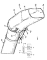
- FIG. 2 is a perspective view of the directable discharge boot of the present invention
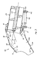
- FIG. 3 is a partially cutaway view of the discharge boot and distal end of the unloading auger tube with the boot at its "nominal" angle;
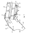
- FIG. 4 is a side elevational view of a partially cutaway cross-sectional view of the boot and the interface between it and the distal end of an unloading auger tube at its steepest angle down;
- FIG. 5 is a partially cutaway cross-sectional view of the boot of the present invention and its interface with the distal end of the auger unloading tube when the boot is at the "grain save” position and the tube has swung back to its storage position;
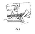
- FIG. 6 is a partially cutaway side view of the interface between the boot and the distal end of the unloading auger tube at the "grain save” position, showing how the dam impingement prevents soybeans or other grain from inadvertent spilling or dribbling out of the boot;
- FIG 7 is a right side elevation of the rear of and the unloading auger tube of the present invention in longitudinal relationship to its combine harvester and the boot is in the "grain save" position.
- combine harvester 10 has its unloading auger tube 20 transversely extending and fully deployed as it unloads grain 100 through discharge boot 30 and into the bed of truck 60.
- Boot 30 can have any convenient shape. Preferably, it is generally cylindrical, but can be more boxy with edges, or venturi-shaped, etc.
- the opening of auger tube 20 at its distal end is peripherally sealed by a joint member 21 which hingedly engages portion 32 of boot 30, which portion 32 interfaces the distal end of the auger tube 20.
- the joint member is preferably rounded or spherical, but can be cylindrical on a horizontal axis, so long as the interface between the tube 20 and boot 30 is adequately sealed.
- Angularly extending from portion 32 of boot 30 is spout end 31 of the boot.
- Joint 21 also serves to seal the interface at end 32 of boot 30.
- buttons, switches, levers and other input devices for engaging and disengaging the on-off function of the auger may be designated at 51.
- Devices for controlling the deployment of the tube 20 and pivoting of boot 30 may be designated at 53. Both input devices are preferably located in the cab 11 of the combine harvester 10 and are programmed through controller 50.
- boot 30 and unloading auger tube 20 have their hinging relationship manifested via pivot points at 41 on the tube, 42 on the lower end of the boot, and 45 on the upper end of the boot.
- there is an additional upper pivot point matingly connected via bracket 42 but on the outside wall (not shown) of boot 30.
- the actuator 40 is preferably a piston and cylinder type actuator, but optionally can be either an electronic, a pneumatic, or an hydraulic device, as desired.
- boot 30 is defined by angularly disposed portions 31 and 32.
- Portion 32 is the portion of boot 30 which interfaces with tube 20 and matingly engages spherical joint 21, allowing opening 23, at the distal end of tube 20, to unload grain 100 traveling via the movement of auger 22 and discharging through boot 30.
- Boot 30 is a hollow boot defined by outer walls 34 and inner walls 33.
- Inner wall 33 is configured or shaped to define, at its lower portion, a dam impingement 35, which slidingly moves along the lower portion of spherical joint 21 as boot 30 pivots.
- the surface shape of dam impingement 35 is in conformity with the surface topography of the spherical joint 21.
- Boot 30 and its dam 35 are depicted in FIG. 3 at a "nominal" position vis-à-vis angle N.
- dam 35 slides further underneath the interface of tube 20 along the lower surface of spherical joint 21 as the boot 30 is pivoted down from its "nominal" angle N to now reflect a steeper, if not the most steep angle D.
- FIG. 5 the position of boot 30 in relationship to tube 20 is shown at a point and time when the boot has been pivoted up above horizontal into the angle G which is the "grain save” position.
- grain 100 as a consequence of dam impingement 35, is inhibited from spilling out of spout open end 36.
- the dam impingement 35 bounds and defines a partial spherical shaped cavity outwardly of the open distal end of the auger tube 20.
- FIG. 6 illustrates a close-up view of dam impingement 35 as it inhibits spillage of, for example, soybeans 100.
- auger 22 has been shutoff at input device A (51) at FIG. 2 and by input device B (53) at FIG. 2 , and the auger tube 20 has been moved to its storage position, longitudinally parallel to the length and direction of combine 10.
- linkage 40 has moved boot 30 into the "grain save” position.
- the pivoting discharge boot 30 can be pneumatically, hydraulically, or preferably electronically controlled by an operator within cab 11 by input devices 51 and 53 through controller 50.
- the method provided by boot 30 will entail, generally, although not being limited to, three principle steps:
Landscapes
- Engineering & Computer Science (AREA)
- Life Sciences & Earth Sciences (AREA)
- Environmental Sciences (AREA)
- Transportation (AREA)
- Mechanical Engineering (AREA)
- Threshing Machine Elements (AREA)
Claims (14)
- Entlade-Schneckenförderrohr (20) eines landwirtschaftlichen Mähdreschers (10), an dem eine lenkbare Auswurfstutzen-Baugruppe (30) angebracht ist, und
dadurch gekennzeichnet, dass die Baugruppe Folgendes umfasst:- einen hohlen Stutzen (30) mit einem offenen Verbindungsteil (32) mit einer inneren teilkreisförmigen Profilform bei Betrachtung in einer seitlichen Richtung,- ein offenes Auslaufrohr (31), das sich unter einem Winkel von dem offenen Verbindungsteil (32) aus erstreckt,- einen Aufpralldamm (35), der sich nach oben benachbart zu dem Auslaufrohr-Teil (31) auf einem unteren Teil des offenen Verbindungsteils (32) erstreckt; und- eine Gelenkdichtung (21), die um ein offenes distales Ende (23) des Schneckenförderrohres (20) herum angeordnet ist und eine Außenoberfläche mit einer teilkreisförmigen Profilform bei Betrachtung von einer seitlichen Richtung aus aufweist, wobei der Verbindungsteil (32) der Innenoberfläche des Stutzens (30) in zusammenpassender Schwenkverbindung mit der Außenoberfläche der Gelenk-dichtung (21) derart angeordnet ist, dass der Stutzen (30) um diese herum über einen Bereich von Positionen schwenkbar ist, die zumindest eine Betriebsstellung (N), die sich von dem offenen distalen Ende des Förderschneckenrohres (20) aus nach unten erstreckt, um eine freie Strömung des Getreides hiervon zu ermöglichen, und eine Getreide-Halteposition (G) einschließt, in der sich der Aufpralldamm (35) nach oben und nach außen über zumindest einen unteren Teil des offenen distalen Endes des Schneckenförderrohres (20) erstreckt, um ein Auslecken von Getreide aus diesem zu verhindern. - Entlade-Schneckenförderrohr nach Anspruch 1, dadurch gekennzeichnet, dass die Baugruppe weiterhin eine Betätigungseinrichtung (40) umfasst, die zwischen dem Entlade-Förderschneckenrohr (20) und der Stutzen-Baugruppe (30) angeordnet ist, wobei die Betätigungseinrichtung in steuerbarer Weise betreibbar ist, um die Stutzenbaugruppe (30) über einen Bereich von Positionen zu verschwenken.
- Entlade-Schneckenförderrohr nach Anspruch 2, dadurch gekennzeichnet, dass die Baugruppe weiterhin eine Eingabevorrichtung (51, 53) an einer entfernten Stelle umfasst, die zur Betriebssteuerung der Betätigungseinrichtung (40) und einer Entlade-Förderschnecke (22) angeschlossen ist, die sich in dem Rohr (20) befindet.
- Entlade-Schneckenförderrohr nach Anspruch 3, dadurch gekennzeichnet, dass die Eingabevorrichtung (51, 53) zum automatischen Steuern der Betätigungseinrichtung (40) zum Bewegen des Stutzens (30) aus der Körner-Halteposition (G) auf eine nominelle Betriebsposition (N) in dem Bereich beim Einschalten oder Drehen der Entlade-Förderschnecke (22) oder unmittelbar hierauf folgend betreibbar ist.
- Entlade-Schneckenförderrohr nach Anspruch 3 oder 4, dadurch gekennzeichnet, dass die Eingabevorrichtung (51, 53) betreibbar ist, um die Betätigungseinrichtung (40) automatisch für eine Bewegung des Stutzens (30) von irgendeiner der Positionen in dem Bereich auf die Körner-Halteposition (G) zu steuern, wenn die Förderschnecke (22) abgeschaltet oder ausgekuppelt wird.
- Entlade-Schneckenförderrohr nach Anspruch 3 bis 5, dadurch gekennzeichnet, dass die Eingabevorrichtung (51, 53) zum automatischen Abschalten oder Auskuppeln der Förderschnecke (22) betreibbar ist, wenn die Betätigungseinrichtung (40) so gesteuert wird, dass sie den Stutzen (30) von einer der Positionen in dem Bereich auf die Körner-Halteposition (G) bewegt.
- Entlade-Schneckenförderrohr nach den Ansprüchen 3 bis 6, dadurch gekennzeichnet, dass die Eingabevorrichtung (51, 53) betreibbar ist, um die Betätigungseinrichtung für eine Bewegung des Stutzens (30) nach oben oder nach unten über eine unbegrenzte Anzahl von Betriebspositionen innerhalb des Bereiches zu steuern.
- Entlade-Schneckenförderrohr nach einem der vorhergehenden Ansprüche, dadurch gekennzeichnet, dass der Verbindungsteil (32) unter Einschluss des Aufpralldamms (35) und der Gelenkdichtung (21), die um das distale Ende des Förderschneckenrohres (20) herum angeordnet ist, eine kugelförmige Gelenk-dichtung bilden, derart, dass wenn sich der Stutzen (30) in der Körner-Halteposition (G) befindet, der Aufpralldamm (35) einen teilkugelförmigen Hohlraum außerhalb des offenen distalen Endes des Schneckenförderrohres (20) begrenzt und bildet.
- Entlade-Schneckenförderrohr nach einem der vorhergehenden Ansprüche, dadurch gekennzeichnet, dass wenn sich der Stutzen in der Betriebsstellung (N) befindet, der Aufpralldamm (35) unterhalb des distalen Endes des Förderschneckenrohres (20) liegt.
- Verfahren zum Entladen von Körnern aus einem Mähdrescher (10) durch ein Schneckenförderrohr (20) hiervon, das eine Schraubenförderschnecke (22) enthält, die zum Entladen von Körner durch ein offenes distales Ende (23) des Rohres (20) hindurch drehbar ist, und
dadurch gekennzeichnet , dass das Verfahren die folgenden Schritte umfasst:Bereitstellen einer lenkbaren Stutzenbaugruppe (30), die auf dem offenen distalen Ende des Rohres (20) befestigt ist, wobei die Stutzen-Baugruppe (30) einen hohlen Stutzen mit einem Auslaufrohr (31) einschließt, das sich von einem Verbindungsteil (32) aus nach außen erstreckt, der für eine Aufwärts-und Abwärts-Schwenkbewegung um das distale Ende herum zwischen einer Körner-Halteposition (G), in der sich das Auslaufrohr (31) nach außen und nach oben von dem offenen distalen Ende aus erstreckt, und zumindest einer Betriebsstellung befestigt ist, in der sich das Auslaufrohr (31) nach außen und nach unten von dem offenen distalen Ende aus erstreckt, wobei der Verbindungsteil (32) eine nach oben gerichtete Innenoberfläche umfasst, die für einen Gleiteingriff mit einer zusammenpassenden, nach unten gerichteten Außenoberfläche auf dem distalen Ende angeordnet ist, wenn der Stutzen verschwenkt wird;- Bereitstellen einer Betätigungseinrichtung (40), die steuerbar betreibbar ist, um den Stutzen (30) zwischen der Körner-Halteposition (G) und der zumindest einen Betriebsstellung in Abhängigkeit von Signalen von einer Eingabevorrichtung (51, 53) zu verschwenken; und- Betreiben der Betätigungseinrichtung zum Bewegen des Stutzens (30) auf die Körner-Halteposition (G) derart, dass sich die Innenoberfläche des Verbindungsteils nach oben von der nach unten gerichteten Außenoberfläche nach außen von einer unteren Position des offenen distalen Endes erstreckt, um das Auslecken von Körnern hieraus zu verhindern. - Verfahren nach Anspruch 10, dadurch gekennzeichnet, dass das Verfahren den weiteren Schritt des Betreibens der Betätigungseinrichtung (40) zum Bewegen des Stutzens (30) auf eine der Betriebsstellungen derart umfasst, dass die Innenoberfläche des Verbindungsteils (32) zumindest im Wesentlichen unter der nach unten gerichteten Oberfläche liegt, wobei sich der Stutzen (30) nach unten und nach außen von dem offenen distalen Ende des Rohres (20) erstreckt, um eine freie Strömung der Körner hieraus zu ermöglichen.
- Verfahren nach Anspruch 10 oder 11, dadurch gekennzeichnet, dass die Eingabevorrichtung (51, 53) so konfiguriert ist, das sie den Betrieb der Förderschnecke (22) gleichzeitig mit dem Betrieb der Betätigungseinrichtung (40) derart steuert, dass wenn die Förderschnecke (22) abgeschaltet oder ausgekuppelt wird, der Schritt des Betreibens der Betätigungseinrichtung (40) zum Bewegen des Stutzens (30) auf die Körner-Halteposition automatisch ausgeführt wird.
- Verfahren nach den Ansprüchen 10 bis 12, dadurch gekennzeichnet, dass die Eingabevorrichtung (51, 53) so konfiguriert ist, das sie den Betrieb der Förderschnecke (22) gleichzeitig mit dem Betrieb der Betätigungseinrichtung (40) derart steuert, dass wenn die Förderschnecke (22) eingeschaltet wird, die Betätigungseinrichtung (40) automatisch so gesteuert wird, dass sie den Stutzen (30) von der Körner-Halteposition (G) auf eine Nenn-Betriebsposition (N) bewegt.
- Verfahren nach den Ansprüchen 10 bis 13, dadurch gekennzeichnet, dass die nach oben gerichtete Innenoberfläche des Verbindungsteils (32) des Stutzens (30) und die nach unten gerichtete Außenoberfläche des distalen Endes des Rohres (20) zusammenpassende Teile (21, 32) einer kugelförmige Gelenkdichtung bilden, die den Stutzen (30) mit dem Rohr (20) verbindet.
Applications Claiming Priority (1)
| Application Number | Priority Date | Filing Date | Title |
|---|---|---|---|
| US12/150,674 US7644816B2 (en) | 2008-04-30 | 2008-04-30 | Grain saving, directable unloader boot assembly |
Publications (2)
| Publication Number | Publication Date |
|---|---|
| EP2113162A1 EP2113162A1 (de) | 2009-11-04 |
| EP2113162B1 true EP2113162B1 (de) | 2011-06-15 |
Family
ID=40802562
Family Applications (1)
| Application Number | Title | Priority Date | Filing Date |
|---|---|---|---|
| EP09158828A Active EP2113162B1 (de) | 2008-04-30 | 2009-04-27 | Ausrichtbare Ausladeraumanordnung zur Getreidekonservierung |
Country Status (3)
| Country | Link |
|---|---|
| US (1) | US7644816B2 (de) |
| EP (1) | EP2113162B1 (de) |
| AT (1) | ATE512580T1 (de) |
Families Citing this family (32)
| Publication number | Priority date | Publication date | Assignee | Title |
|---|---|---|---|---|
| US7946416B2 (en) * | 2008-10-31 | 2011-05-24 | Rodono Industries Ltd. | Retractable transfer conveyor |
| US8505711B2 (en) | 2009-02-05 | 2013-08-13 | Poet Research, Inc. | System for conveying biomass for collection, transport, or processing |
| US7938613B2 (en) * | 2009-04-15 | 2011-05-10 | Cnh America Llc | Grain unloading conveyor with directable spout and closure apparatus and system |
| USD619627S1 (en) * | 2009-05-29 | 2010-07-13 | Claas Kgaa Mbh | Harvester spout |
| US8197312B2 (en) * | 2009-12-04 | 2012-06-12 | Cnh America Llc | Extension for an agricultural combine unloader tube |
| US20120024670A1 (en) * | 2010-07-29 | 2012-02-02 | Robert Koerselman | Adjustable Rotational Discharge Assembly for a Conveyor |
| FI122826B (fi) * | 2010-10-27 | 2012-07-13 | Andritz Oy | Laite ja menetelmä vierivän aineksen siirtämiseksi |
| US8863932B1 (en) * | 2011-05-31 | 2014-10-21 | Karl W. Nolin | Method, baffle free angle adjustable apparatus and system for delivering dry bulk-free flowing material into a container |
| US20130096782A1 (en) * | 2011-10-13 | 2013-04-18 | Agco Corporation | Control Method for a Pivoting Grain Unloading Spout for Use with Combine Harvesters |
| USD667850S1 (en) * | 2012-02-13 | 2012-09-25 | J. & M. Manufacturing Co., Inc. | Grain auger housing having an askewed discharge outlet attachment |
| US9468145B2 (en) | 2012-10-19 | 2016-10-18 | Cnh Industrial America Llc | Seal for unloading conveyor arrangement |
| US9038814B2 (en) | 2012-11-08 | 2015-05-26 | Cnh Industrial America Llc | Grain saver catch for an agricultural combine |
| US8747195B2 (en) * | 2012-11-12 | 2014-06-10 | Cnh Industrial America Llc | Unloader system for an agricultural combine |
| CA2821182A1 (en) * | 2013-07-17 | 2015-01-17 | Sheldon Affleck | Method and apparatus for loading railcars with crop material |
| CN103688675A (zh) * | 2013-12-24 | 2014-04-02 | 湖州丰源农业装备制造有限公司 | 一种收割机防漏粮结构 |
| US9487362B2 (en) * | 2014-06-03 | 2016-11-08 | Keith T. Dismuke, Sr. | Auger pan/hopper splash shield and safety guard |
| CA2932588C (en) * | 2015-06-08 | 2023-08-01 | Ty-Crop Manufacturing Ltd. | Conveyor transition for material handling |
| US10834872B2 (en) * | 2015-07-02 | 2020-11-17 | Cnh Industriall America Llc | Unload spout inclination limit adjust system and method |
| US9604785B1 (en) * | 2016-02-08 | 2017-03-28 | J. & M. Manufacturing Co., Inc. | Telescoping flow control discharge spout assembly for a conveyor of granular material |
| WO2017141151A1 (en) * | 2016-02-15 | 2017-08-24 | King John M | Devices, systems, and methods related to extracting infill from artificial turf |
| EP3525572B1 (de) * | 2016-10-11 | 2021-06-30 | AGCO Corporation | Kontrollsystem zur einbehaltung verschütteter mengen für ein mähdrescherentladesystem |
| US9914589B1 (en) * | 2017-04-06 | 2018-03-13 | John Teel | Automated feeder chute system |
| US11635768B2 (en) | 2020-04-28 | 2023-04-25 | Cnh Industrial America Llc | System for coordinating control of multiple work vehicles |
| US12029165B2 (en) * | 2020-04-28 | 2024-07-09 | Deere And Company | Sugarcane harvester billet discharge control |
| US12137632B2 (en) | 2021-01-22 | 2024-11-12 | Deere & Company | Residue management control system for harvester |
| US12137631B2 (en) | 2021-01-22 | 2024-11-12 | Deere & Company | Residue management control system for harvester |
| US12201061B2 (en) | 2021-11-16 | 2025-01-21 | Deere & Company | Adjustable billet deflector |
| US12545523B2 (en) * | 2023-01-13 | 2026-02-10 | Travis Hughes | System for transferring crop materials from a harvester in a confined area of an agricultural field |
| US12685267B2 (en) | 2023-04-27 | 2026-07-21 | Cnh Industrial America Llc | Unload tube for agricultural vehicle |
| US12477994B2 (en) | 2023-07-14 | 2025-11-25 | Cnh Industrial America Llc | Unload spout for agricultural vehicle |
| WO2025049106A1 (en) * | 2023-08-28 | 2025-03-06 | Ctb, Inc. | Adjustable transition for connecting discharge end of conveyor to grain storage bin or grain dryer |
| US12698158B2 (en) * | 2023-08-28 | 2026-08-04 | Ctb, Inc. | Adjustable transition for connecting discharge end of conveyor to grain storage bin or grain dryer |
Family Cites Families (25)
| Publication number | Priority date | Publication date | Assignee | Title |
|---|---|---|---|---|
| US80880A (en) * | 1868-08-11 | Improvement in machines for cutting open ditches | ||
| US804511A (en) * | 1905-03-11 | 1905-11-14 | Theodore W Snow | Stand-pipe. |
| US1721258A (en) | 1927-05-12 | 1929-07-16 | Borden Co | Apparatus for transferring powder and the like |
| US1885656A (en) | 1931-04-16 | 1932-11-01 | Gullett Gin Co | Double conveyer distributor |
| US2456744A (en) * | 1947-01-11 | 1948-12-21 | Pacific Coast Eng Co | Universal pipe coupling |
| US2625001A (en) | 1950-02-01 | 1953-01-13 | Heun Rudolph George | Grain unloading attachment |
| US3447669A (en) | 1967-03-24 | 1969-06-03 | Martin Mayrath | Auger conveyor discharge unit with safety outlet |
| US3575306A (en) * | 1969-01-24 | 1971-04-20 | Helix Corp | Integrated single-pivot auger box |
| US3722715A (en) | 1970-10-15 | 1973-03-27 | G Young | Variable load auger apparatus |
| US3815781A (en) | 1972-11-16 | 1974-06-11 | C Armstrong | Vending machine with improved auger conveyor |
| US3963112A (en) | 1975-03-14 | 1976-06-15 | Sperry Rand Corporation | Windguard for grain distributor |
| US4164327A (en) | 1978-04-07 | 1979-08-14 | Clark Donald Y | Grain spreader |
| US4881855A (en) | 1988-08-09 | 1989-11-21 | Rem Manufacturing Ltd. | Vacuum particulate transfer apparatus |
| US4988240A (en) * | 1988-12-05 | 1991-01-29 | Thompson Andy L | Material transfer assembly |
| US5167581A (en) | 1991-07-03 | 1992-12-01 | Steve Haag | Directable spout for a conveyor |
| CA2100907A1 (en) | 1993-07-20 | 1995-01-21 | Karl F. Seemann | No-nest bird gate |
| CA2104266A1 (en) * | 1993-08-17 | 1995-02-18 | Dennis A. Scarrow | Auger or conveyor discharge spout |
| US5538388A (en) | 1995-03-10 | 1996-07-23 | Deweze Manufacturing, Inc. | Grain cart equipped with independent hydraulically driven discharge augers |
| DE29700426U1 (de) * | 1997-01-11 | 1997-05-15 | Claas KGaA, 33428 Harsewinkel | Selbstfahrender Feldhäcksler mit am Ende seines Auswurfrohres angeordneter verschwenkbarer Klappe |
| JP3690036B2 (ja) | 1997-02-12 | 2005-08-31 | 井関農機株式会社 | コンバイン等の排穀オ−ガ |
| JPH11187753A (ja) | 1997-12-26 | 1999-07-13 | Mitsubishi Agricult Mach Co Ltd | コンバイン |
| US6296435B1 (en) * | 2000-02-09 | 2001-10-02 | J. & M. Manufacturing Co., Inc. | Grain wagon having an unloading conveyor with a moveable discharge spout controlled from a tow vehicle |
| CA2304412C (en) | 2000-04-04 | 2004-10-12 | Darcy Tofin | Auger flow control spout with pressure relief |
| US6691861B2 (en) | 2001-10-25 | 2004-02-17 | Deere & Company | Auger discharge chute with dribble door |
| US6974021B1 (en) | 2004-05-25 | 2005-12-13 | Craig Boevers | Adjustable grain spout assembly |
-
2008
- 2008-04-30 US US12/150,674 patent/US7644816B2/en active Active
-
2009
- 2009-04-27 EP EP09158828A patent/EP2113162B1/de active Active
- 2009-04-27 AT AT09158828T patent/ATE512580T1/de not_active IP Right Cessation
Also Published As
| Publication number | Publication date |
|---|---|
| US7644816B2 (en) | 2010-01-12 |
| US20090272619A1 (en) | 2009-11-05 |
| EP2113162A1 (de) | 2009-11-04 |
| ATE512580T1 (de) | 2011-07-15 |
Similar Documents
| Publication | Publication Date | Title |
|---|---|---|
| US7644816B2 (en) | Grain saving, directable unloader boot assembly | |
| EP2241175B1 (de) | Kornentladungsförderer mit lenkbarer Ausgussrinne und Verschlussvorrichtung und -system | |
| EP2675263B1 (de) | System und verfahren zur steuerung des auswurfrohrs für feldhäcksler | |
| CA2334728C (en) | Grain wagon having an unloading conveyor with a movable discharge spout controlled from a tow vehicle | |
| US9002591B2 (en) | Harvester spout control system and method | |
| AU2009202834B2 (en) | Tractor mounted unloading conveyor | |
| US20050238469A1 (en) | Loading conveyor with folding hopper for agricultrual commodity carts | |
| US8146974B2 (en) | Expandable grain tank for agricultural combines | |
| US11641805B2 (en) | Convertible dual-sided auger system for a farm implement | |
| US20170055454A1 (en) | Adjustable grain cart auger | |
| AU2013201230A1 (en) | Grain Cart Having An Inclined Folding Unloading Auger Conveyor With An Askewed Flow Control Spout | |
| US3938684A (en) | Combine unloading auger drive | |
| EP1606130B1 (de) | Lkw mit einem planenabdecksystem | |
| US5890867A (en) | Rotatable feedgate | |
| US20070237617A1 (en) | Linkage for on-off loading and dumping of a body on a truck frame | |
| US20130034412A1 (en) | Load leveling modification for front loading refuse truck | |
| US20040051342A1 (en) | Folding roof in particular for station wagon, with pivoting arms and levers | |
| AU2016225808B2 (en) | Agricultural vehicle conveyance linkage | |
| CA1175378A (en) | Material transfer device | |
| RU2780477C1 (ru) | Выгрузное устройство сельскохозяйственной уборочной машины | |
| CN223737228U (zh) | 一种自动作业无人清舱机 | |
| JP2001327216A (ja) | コンバイン | |
| USRE20947E (en) | Refuse truck | |
| JP5503475B2 (ja) | コンバインにおける穀粒排出用オーガの操作装置 | |
| CA2206542C (en) | Rotatable feedgate |
Legal Events
| Date | Code | Title | Description |
|---|---|---|---|
| PUAI | Public reference made under article 153(3) epc to a published international application that has entered the european phase |
Free format text: ORIGINAL CODE: 0009012 |
|
| AK | Designated contracting states |
Kind code of ref document: A1 Designated state(s): AT BE BG CH CY CZ DE DK EE ES FI FR GB GR HR HU IE IS IT LI LT LU LV MC MK MT NL NO PL PT RO SE SI SK TR |
|
| 17P | Request for examination filed |
Effective date: 20100504 |
|
| 17Q | First examination report despatched |
Effective date: 20100609 |
|
| GRAP | Despatch of communication of intention to grant a patent |
Free format text: ORIGINAL CODE: EPIDOSNIGR1 |
|
| GRAS | Grant fee paid |
Free format text: ORIGINAL CODE: EPIDOSNIGR3 |
|
| GRAA | (expected) grant |
Free format text: ORIGINAL CODE: 0009210 |
|
| AK | Designated contracting states |
Kind code of ref document: B1 Designated state(s): AT BE BG CH CY CZ DE DK EE ES FI FR GB GR HR HU IE IS IT LI LT LU LV MC MK MT NL NO PL PT RO SE SI SK TR |
|
| REG | Reference to a national code |
Ref country code: GB Ref legal event code: FG4D Ref country code: CH Ref legal event code: EP |
|
| REG | Reference to a national code |
Ref country code: IE Ref legal event code: FG4D |
|
| REG | Reference to a national code |
Ref country code: DE Ref legal event code: R096 Ref document number: 602009001531 Country of ref document: DE Effective date: 20110728 |
|
| REG | Reference to a national code |
Ref country code: NL Ref legal event code: VDEP Effective date: 20110615 |
|
| PG25 | Lapsed in a contracting state [announced via postgrant information from national office to epo] |
Ref country code: NO Free format text: LAPSE BECAUSE OF FAILURE TO SUBMIT A TRANSLATION OF THE DESCRIPTION OR TO PAY THE FEE WITHIN THE PRESCRIBED TIME-LIMIT Effective date: 20110915 Ref country code: SE Free format text: LAPSE BECAUSE OF FAILURE TO SUBMIT A TRANSLATION OF THE DESCRIPTION OR TO PAY THE FEE WITHIN THE PRESCRIBED TIME-LIMIT Effective date: 20110615 Ref country code: LT Free format text: LAPSE BECAUSE OF FAILURE TO SUBMIT A TRANSLATION OF THE DESCRIPTION OR TO PAY THE FEE WITHIN THE PRESCRIBED TIME-LIMIT Effective date: 20110615 Ref country code: HR Free format text: LAPSE BECAUSE OF FAILURE TO SUBMIT A TRANSLATION OF THE DESCRIPTION OR TO PAY THE FEE WITHIN THE PRESCRIBED TIME-LIMIT Effective date: 20110615 |
|
| PG25 | Lapsed in a contracting state [announced via postgrant information from national office to epo] |
Ref country code: LV Free format text: LAPSE BECAUSE OF FAILURE TO SUBMIT A TRANSLATION OF THE DESCRIPTION OR TO PAY THE FEE WITHIN THE PRESCRIBED TIME-LIMIT Effective date: 20110615 Ref country code: AT Free format text: LAPSE BECAUSE OF FAILURE TO SUBMIT A TRANSLATION OF THE DESCRIPTION OR TO PAY THE FEE WITHIN THE PRESCRIBED TIME-LIMIT Effective date: 20110615 Ref country code: GR Free format text: LAPSE BECAUSE OF FAILURE TO SUBMIT A TRANSLATION OF THE DESCRIPTION OR TO PAY THE FEE WITHIN THE PRESCRIBED TIME-LIMIT Effective date: 20110916 Ref country code: FI Free format text: LAPSE BECAUSE OF FAILURE TO SUBMIT A TRANSLATION OF THE DESCRIPTION OR TO PAY THE FEE WITHIN THE PRESCRIBED TIME-LIMIT Effective date: 20110615 Ref country code: SI Free format text: LAPSE BECAUSE OF FAILURE TO SUBMIT A TRANSLATION OF THE DESCRIPTION OR TO PAY THE FEE WITHIN THE PRESCRIBED TIME-LIMIT Effective date: 20110615 Ref country code: CY Free format text: LAPSE BECAUSE OF FAILURE TO SUBMIT A TRANSLATION OF THE DESCRIPTION OR TO PAY THE FEE WITHIN THE PRESCRIBED TIME-LIMIT Effective date: 20110615 |
|
| PG25 | Lapsed in a contracting state [announced via postgrant information from national office to epo] |
Ref country code: NL Free format text: LAPSE BECAUSE OF FAILURE TO SUBMIT A TRANSLATION OF THE DESCRIPTION OR TO PAY THE FEE WITHIN THE PRESCRIBED TIME-LIMIT Effective date: 20110615 |
|
| PG25 | Lapsed in a contracting state [announced via postgrant information from national office to epo] |
Ref country code: PT Free format text: LAPSE BECAUSE OF FAILURE TO SUBMIT A TRANSLATION OF THE DESCRIPTION OR TO PAY THE FEE WITHIN THE PRESCRIBED TIME-LIMIT Effective date: 20111017 Ref country code: EE Free format text: LAPSE BECAUSE OF FAILURE TO SUBMIT A TRANSLATION OF THE DESCRIPTION OR TO PAY THE FEE WITHIN THE PRESCRIBED TIME-LIMIT Effective date: 20110615 Ref country code: IS Free format text: LAPSE BECAUSE OF FAILURE TO SUBMIT A TRANSLATION OF THE DESCRIPTION OR TO PAY THE FEE WITHIN THE PRESCRIBED TIME-LIMIT Effective date: 20111015 Ref country code: CZ Free format text: LAPSE BECAUSE OF FAILURE TO SUBMIT A TRANSLATION OF THE DESCRIPTION OR TO PAY THE FEE WITHIN THE PRESCRIBED TIME-LIMIT Effective date: 20110615 |
|
| PG25 | Lapsed in a contracting state [announced via postgrant information from national office to epo] |
Ref country code: PL Free format text: LAPSE BECAUSE OF FAILURE TO SUBMIT A TRANSLATION OF THE DESCRIPTION OR TO PAY THE FEE WITHIN THE PRESCRIBED TIME-LIMIT Effective date: 20110615 Ref country code: SK Free format text: LAPSE BECAUSE OF FAILURE TO SUBMIT A TRANSLATION OF THE DESCRIPTION OR TO PAY THE FEE WITHIN THE PRESCRIBED TIME-LIMIT Effective date: 20110615 |
|
| PLBE | No opposition filed within time limit |
Free format text: ORIGINAL CODE: 0009261 |
|
| STAA | Information on the status of an ep patent application or granted ep patent |
Free format text: STATUS: NO OPPOSITION FILED WITHIN TIME LIMIT |
|
| 26N | No opposition filed |
Effective date: 20120316 |
|
| PG25 | Lapsed in a contracting state [announced via postgrant information from national office to epo] |
Ref country code: DK Free format text: LAPSE BECAUSE OF FAILURE TO SUBMIT A TRANSLATION OF THE DESCRIPTION OR TO PAY THE FEE WITHIN THE PRESCRIBED TIME-LIMIT Effective date: 20110615 |
|
| REG | Reference to a national code |
Ref country code: DE Ref legal event code: R097 Ref document number: 602009001531 Country of ref document: DE Effective date: 20120316 |
|
| PG25 | Lapsed in a contracting state [announced via postgrant information from national office to epo] |
Ref country code: MC Free format text: LAPSE BECAUSE OF NON-PAYMENT OF DUE FEES Effective date: 20120430 |
|
| PG25 | Lapsed in a contracting state [announced via postgrant information from national office to epo] |
Ref country code: MK Free format text: LAPSE BECAUSE OF FAILURE TO SUBMIT A TRANSLATION OF THE DESCRIPTION OR TO PAY THE FEE WITHIN THE PRESCRIBED TIME-LIMIT Effective date: 20110615 |
|
| PG25 | Lapsed in a contracting state [announced via postgrant information from national office to epo] |
Ref country code: ES Free format text: LAPSE BECAUSE OF FAILURE TO SUBMIT A TRANSLATION OF THE DESCRIPTION OR TO PAY THE FEE WITHIN THE PRESCRIBED TIME-LIMIT Effective date: 20110926 Ref country code: IE Free format text: LAPSE BECAUSE OF NON-PAYMENT OF DUE FEES Effective date: 20120427 |
|
| PG25 | Lapsed in a contracting state [announced via postgrant information from national office to epo] |
Ref country code: BG Free format text: LAPSE BECAUSE OF FAILURE TO SUBMIT A TRANSLATION OF THE DESCRIPTION OR TO PAY THE FEE WITHIN THE PRESCRIBED TIME-LIMIT Effective date: 20110915 |
|
| PG25 | Lapsed in a contracting state [announced via postgrant information from national office to epo] |
Ref country code: MT Free format text: LAPSE BECAUSE OF FAILURE TO SUBMIT A TRANSLATION OF THE DESCRIPTION OR TO PAY THE FEE WITHIN THE PRESCRIBED TIME-LIMIT Effective date: 20110615 |
|
| REG | Reference to a national code |
Ref country code: CH Ref legal event code: PL |
|
| PG25 | Lapsed in a contracting state [announced via postgrant information from national office to epo] |
Ref country code: CH Free format text: LAPSE BECAUSE OF NON-PAYMENT OF DUE FEES Effective date: 20130430 Ref country code: LI Free format text: LAPSE BECAUSE OF NON-PAYMENT OF DUE FEES Effective date: 20130430 |
|
| REG | Reference to a national code |
Ref country code: DE Ref legal event code: R082 Ref document number: 602009001531 Country of ref document: DE Representative=s name: PATENTANWAELTE WALLACH, KOCH & PARTNER, DE |
|
| PG25 | Lapsed in a contracting state [announced via postgrant information from national office to epo] |
Ref country code: TR Free format text: LAPSE BECAUSE OF FAILURE TO SUBMIT A TRANSLATION OF THE DESCRIPTION OR TO PAY THE FEE WITHIN THE PRESCRIBED TIME-LIMIT Effective date: 20110615 |
|
| PG25 | Lapsed in a contracting state [announced via postgrant information from national office to epo] |
Ref country code: LU Free format text: LAPSE BECAUSE OF NON-PAYMENT OF DUE FEES Effective date: 20120427 |
|
| REG | Reference to a national code |
Ref country code: DE Ref legal event code: R082 Ref document number: 602009001531 Country of ref document: DE Representative=s name: PATENTANWAELTE WALLACH, KOCH, DR. HAIBACH, FEL, DE Effective date: 20140428 Ref country code: DE Ref legal event code: R081 Ref document number: 602009001531 Country of ref document: DE Owner name: CNH INDUSTRIAL BELGIUM NV, BE Free format text: FORMER OWNER: CNH BELGIUM NV, ZEDELGEM, BE Effective date: 20140428 Ref country code: DE Ref legal event code: R082 Ref document number: 602009001531 Country of ref document: DE Representative=s name: PATENTANWAELTE WALLACH, KOCH & PARTNER, DE Effective date: 20140428 |
|
| PG25 | Lapsed in a contracting state [announced via postgrant information from national office to epo] |
Ref country code: HU Free format text: LAPSE BECAUSE OF FAILURE TO SUBMIT A TRANSLATION OF THE DESCRIPTION OR TO PAY THE FEE WITHIN THE PRESCRIBED TIME-LIMIT Effective date: 20090427 |
|
| REG | Reference to a national code |
Ref country code: FR Ref legal event code: CD Owner name: CNH INDUSTRIAL BELGIUM NV Effective date: 20140725 |
|
| REG | Reference to a national code |
Ref country code: FR Ref legal event code: PLFP Year of fee payment: 8 |
|
| REG | Reference to a national code |
Ref country code: FR Ref legal event code: PLFP Year of fee payment: 9 |
|
| REG | Reference to a national code |
Ref country code: FR Ref legal event code: PLFP Year of fee payment: 10 |
|
| REG | Reference to a national code |
Ref country code: DE Ref legal event code: R082 Ref document number: 602009001531 Country of ref document: DE Representative=s name: MEISSNER BOLTE PATENTANWAELTE RECHTSANWAELTE P, DE |
|
| PGFP | Annual fee paid to national office [announced via postgrant information from national office to epo] |
Ref country code: IT Payment date: 20230412 Year of fee payment: 15 |
|
| PGFP | Annual fee paid to national office [announced via postgrant information from national office to epo] |
Ref country code: BE Payment date: 20230420 Year of fee payment: 15 |
|
| PGFP | Annual fee paid to national office [announced via postgrant information from national office to epo] |
Ref country code: GB Payment date: 20230420 Year of fee payment: 15 |
|
| GBPC | Gb: european patent ceased through non-payment of renewal fee |
Effective date: 20240427 |
|
| REG | Reference to a national code |
Ref country code: BE Ref legal event code: MM Effective date: 20240430 |
|
| PG25 | Lapsed in a contracting state [announced via postgrant information from national office to epo] |
Ref country code: BE Free format text: LAPSE BECAUSE OF NON-PAYMENT OF DUE FEES Effective date: 20240430 |
|
| PG25 | Lapsed in a contracting state [announced via postgrant information from national office to epo] |
Ref country code: GB Free format text: LAPSE BECAUSE OF NON-PAYMENT OF DUE FEES Effective date: 20240427 |
|
| PG25 | Lapsed in a contracting state [announced via postgrant information from national office to epo] |
Ref country code: GB Free format text: LAPSE BECAUSE OF NON-PAYMENT OF DUE FEES Effective date: 20240427 Ref country code: BE Free format text: LAPSE BECAUSE OF NON-PAYMENT OF DUE FEES Effective date: 20240430 |
|
| PG25 | Lapsed in a contracting state [announced via postgrant information from national office to epo] |
Ref country code: IT Free format text: LAPSE BECAUSE OF NON-PAYMENT OF DUE FEES Effective date: 20240427 |
|
| PGFP | Annual fee paid to national office [announced via postgrant information from national office to epo] |
Ref country code: DE Payment date: 20260421 Year of fee payment: 18 |
|
| PGFP | Annual fee paid to national office [announced via postgrant information from national office to epo] |
Ref country code: FR Payment date: 20260423 Year of fee payment: 18 |