EP2113345A1 - Main de robot d'un robot industriel - Google Patents
Main de robot d'un robot industriel Download PDFInfo
- Publication number
- EP2113345A1 EP2113345A1 EP07792481A EP07792481A EP2113345A1 EP 2113345 A1 EP2113345 A1 EP 2113345A1 EP 07792481 A EP07792481 A EP 07792481A EP 07792481 A EP07792481 A EP 07792481A EP 2113345 A1 EP2113345 A1 EP 2113345A1
- Authority
- EP
- European Patent Office
- Prior art keywords
- pair
- hand
- finger bodies
- workpiece
- finger
- Prior art date
- Legal status (The legal status is an assumption and is not a legal conclusion. Google has not performed a legal analysis and makes no representation as to the accuracy of the status listed.)
- Withdrawn
Links
Images




Classifications
-
- B—PERFORMING OPERATIONS; TRANSPORTING
- B25—HAND TOOLS; PORTABLE POWER-DRIVEN TOOLS; MANIPULATORS
- B25J—MANIPULATORS; CHAMBERS PROVIDED WITH MANIPULATION DEVICES
- B25J15/00—Gripping heads and other end effectors
- B25J15/08—Gripping heads and other end effectors having finger members
-
- B—PERFORMING OPERATIONS; TRANSPORTING
- B25—HAND TOOLS; PORTABLE POWER-DRIVEN TOOLS; MANIPULATORS
- B25J—MANIPULATORS; CHAMBERS PROVIDED WITH MANIPULATION DEVICES
- B25J15/00—Gripping heads and other end effectors
- B25J15/02—Gripping heads and other end effectors servo-actuated
- B25J15/0253—Gripping heads and other end effectors servo-actuated comprising parallel grippers
- B25J15/026—Gripping heads and other end effectors servo-actuated comprising parallel grippers actuated by gears
-
- B—PERFORMING OPERATIONS; TRANSPORTING
- B25—HAND TOOLS; PORTABLE POWER-DRIVEN TOOLS; MANIPULATORS
- B25J—MANIPULATORS; CHAMBERS PROVIDED WITH MANIPULATION DEVICES
- B25J13/00—Controls for manipulators
- B25J13/08—Controls for manipulators by means of sensing devices, e.g. viewing or touching devices
-
- B—PERFORMING OPERATIONS; TRANSPORTING
- B25—HAND TOOLS; PORTABLE POWER-DRIVEN TOOLS; MANIPULATORS
- B25J—MANIPULATORS; CHAMBERS PROVIDED WITH MANIPULATION DEVICES
- B25J15/00—Gripping heads and other end effectors
- B25J15/04—Gripping heads and other end effectors with provision for the remote detachment or exchange of the head or parts thereof
Definitions
- This invention relates to a robot hand for industrial robots capable of easily gripping a targeted workpiece among multiple workpieces in various sizes without being interfered by other workpieces at production steps and the like.
- a conventionally known robot hand for industrial robots sandwiches and picks up a targeted workpiece from multiple workpieces in various sizes at production steps and the like.
- There are various mechanisms for such robot hands but a generally used robot hand has a pair of finger bodies gripping a workpiece by changing the griping clearance thereof.
- the pair of finger bodies move in directions away from each other to arrange the pair of finger bodies at a maximum open position forming the widest open clearance to form a maximum open clearance. Then, the finger bodies move to position the targeted workpiece between the pair of finger bodies forming the maximum open clearance. Then, the finger bodies slide from the maximum open position to a position at which the pair of finger bodies comes in contact with both sides of the workpiece to grip the targeted workpiece.
- the finger bodies of the conventional robot hand form the maximum open clearance until just before starting to slide inwardly. Accordingly, where the robot hand is to grip a workpiece having an external diameter greatly smaller than the maximum open clearance formed by the pair of finger bodies, the finger bodies are likely to come in contact with other workpieces around the targeted workpiece among multiple workpieces randomly placed on a work table when the finger bodies come close to the targeted workpiece to position the targeted workpiece between the pair of finger bodies, because the finger bodies have the maximum open clearance greatly wider than the external diameter of the targeted workpiece. Thus, there raises a disadvantage that it is difficult for the finger bodies to grip the workpiece.
- Patent Reference 1 discloses, a robot hand is conventionally known that can form a standby open clearance slightly wider than the external diameter of a workpiece in addition to the maximum open clearance and can adjust the standby open clearance of the finger bodies depending on the external diameter of the targeted workpiece.
- Patent Reference 1 Japanese Un-examined Patent Application Publication No. H5-177576
- the invention disclosed in Patent Reference 1 has a pair of finger bodies pivotally movable about an axis, a clamp cylinder connected to the pair of the finger bodies, and a standby cylinder adjacent to the clamp cylinder.
- the standby cylinder has an adjustment means capable of adjusting a slide amount of a piston rod at the tip of the standby cylinder, and the standby open clearance of the pair of finger bodies can be adjusted to a desired amount by adjusting the adjustment means and varying the slide amount of the piston rod.
- the standby open clearance slightly wider than the external diameter of the workpiece to be gripped can be formed by adjusting the adjustment means. Accordingly, the pair of finger bodies can be placed at both sides of the targeted workpiece among multiple workpieces in various sizes without coming in contact with other workpieces, thus being capable of easily griping the targeted workpiece.
- Patent Reference 1 can shorten a time to inwardly slide the finger bodies to render the finger bodies in contact with both sides of the workpiece.
- the robot hand disclosed in Patent Reference 1 can only form a constant standby open clearance previously adjusted by the adjustment means. That is, where the maximum open clearance of the pair of the finger bodies is changed to another standby open clearance, the adjustment means must be adjusted on every such occasion. Accordingly, where the robot hand is to consecutively grip multiple workpieces in various external diameters, the robot hand must have the adjustment means perform adjustment depending on the external diameter of each workpiece to change the standby open clearance of the finger bodies every time gripping the workpiece in a different external diameter, thus such work takes time and is troublesome to deteriorate the workability.
- the robot hand of the present invention can easily have a pair of finger bodies form, in addition to the maximum open clearance, the standby open clearance slightly wider than the external diameter of each workpiece, and can rapidly consecutively form the standby open clearance varying depending on each of various external diameters of the multiple work pieces, thus improving the workability when consecutively or randomly transporting workpieces in various sizes.
- the robot hand of the present invention has a rack and pinion mechanism, a stopper mechanism, and a sensor mechanism.
- the rack and pinion mechanism has a pair of hand pistons, connected by a connection rod, slidably inserted in a hand cylinder, and also has openings for a pressurized gas on the outside of the hand cylinder at the axially end portions of the pair of the hand piston.
- a driving rack gear is formed on the connection rod, and the driving rack gear engages with a driving pinion gear arranged on a penetrating axis, which is rotatably arranged in the hand cylinder to penetrate the hand cylinder. Both ends of the penetrating axis protrude from the hand cylinder, and a driven pinion gear is formed on the external periphery of the lower end of the penetrating axis.
- the driven pinion gear engages with a pair of driven rack gears formed on the pair of finger bodies, so that the pair of finger bodies can slide in an axial direction of the hand cylinder.
- the stopper mechanism can engage with the penetrating axis protruding upward from the hand cylinder to control a position at which the finger bodies stop.
- the stopper mechanism may have a stopper gear secured to the upper end of the penetrating axis of the rack and pinion mechanism and a stopper body arranged reciprocally movably facing the stopper gear to be able to engage with the stopper gear so that the reciprocal movement of the stopper body may be controlled by a detection signal of one of the multiple sensors.
- the sensor mechanism has multiple sensors spaced apart prescribed intervals, and the multiple sensors face an inner portion of a widthwise moving direction of the finger bodies of the rack and pinion mechanism to be able to detect a position of one of the finger bodies.
- the multiple sensors may be detachably and movably secured to an elongated hole, formed parallel to the moving direction of the finger bodies, on a sensor plate arranged on the hand cylinder.
- one of the multiple sensors of the sensor mechanism is first rendered in a state ready for detection, the one being capable of determining that a clearance between the pair of the finger bodies is narrower than a maximum open clearance of the pair of the finger bodies and wider than an external diameter of the workpiece to be gripped. It is to be noted that one of the multiple sensors may be rendered in the state ready for detection in advance depending on the workpiece to be gripped.
- the finger bodies slide inwardly to come close to the one of the multiple sensors ready for detection.
- the one of the multiple sensors detects the finger bodies, and activates a control device of the stopper mechanism to stop the pair of the finger bodies, thereby forming a standby open clearance between the pair of the finger bodies.
- the robot hand moves with the formed standby open clearance, and positions the external diameter of the workpiece to be gripped between the standby open clearance of the pair of the finger bodies.
- the stopper mechanism is released to release the stopped finger bodies, thereby having the finger bodies slide inwardly to narrow the standby open clearance to come in contact with both sides of the workpiece, and thus, the workpiece can be gripped.
- This invention is structured as described above, and accordingly, by rendering one of the multiple sensors in a state ready for detection, the pair of finger bodies can be easily stopped at the one of the multiple sensors ready for detection.
- the standby open clearance slightly wider than the external diameter of the workpiece to be gripped can be formed. Therefore, by changing one of the sensors to be rendered in a state ready for detection to adjust a position at which the finger bodies stop whenever necessary, the width of the standby open clearance of the finger bodies can be easily and rapidly changed.
- the robot hand of the present invention can easily form the standby open clearance slightly wider than the external diameter of each workpiece, and can rapidly consecutively form the standby open clearance varying depending on various external diameters of the multiple work pieces, thus improving the workability when consecutively or randomly transporting workpieces in various sizes.
- Fig. 3 is a cross sectional view along A-A line in Fig. 2 .
- a rack and pinion mechanism (1) of the present embodiment is hereinafter described in detail.
- a column shaped hand cylinder chamber (3) is formed in a hand cylinder (2) and penetrates the hand cylinder (2) with both ends of the hand cylinder chamber (3) being sealed by a pair of sealing wall (4), (5), and a pair of hand pistons (8), (10) having gaskets (6), (7) secured to the external periphery thereof is arranged in the hand cylinder chamber (3) in a manner that the pair of hand pistons (8), (10) are slidably inserted into the hand cylinder chamber (3).
- the pair of hand pistons (8), (10) is connected by a connection rod (12) having a driving rack gear (11) formed thereon and by a pillar (13) arranged parallel to the connection rod (12) at a constant insertion clearance from the connection rod (12) as shown in Fig. 3 .
- a first opening (14) and a second opening (15) are arranged on the outside of the hand cylinder (2) at axially end portions of the hand pistons (8), (10) for introducing and discharging a pressurized gas.
- the pressurized gas is introduced to and discharged from the hand cylinder (2) via the first opening (14) and the second opening (15), and pushing force of the pressurized gas enables the hand pistons (8), (10) to slide reciprocally in the axial direction of the hand cylinder (2).
- a column shaped penetrating axis (16) penetrates the hand cylinder (2) in a direction perpendicular to the axial direction of the hand cylinder (2) at the center of the hand cylinder (2) in the longitudinal direction thereof between the insertion clearance of the pillar (13) and the connection rod (12), and is arranged to have the top end and the bottom end of the penetrating axis (16) protrude externally from the hand cylinder (2).
- the penetrating axis (16) is rotatably supported by the hand cylinder with bearings (17), (18).
- a driving pinion gear (20) is formed opposite to the driving rack gear (11) to be able to engage with the driving rack gear (11).
- a driven pinion gear (21) is arranged on the external periphery of the lower end of the penetrating axis (16) formed protruding from the hand cylinder (2) as described above.
- a pair of rail guides (23), (24) is continuously arranged in the longitudinal direction of the hand cylinder (2) on both sides of the bottom (22) of the hand cylinder (2).
- Liner guides (25), (26) capable of converting a sliding guide face into a roller guide face are slidably arranged along the guides (24), (25).
- a pair of driven rack gears (30), (31) is respectively secured to the bottom of the liner guides (24), (25) to engaged with the driven pinion gear (21) arranged on the lower end of the penetrating axis (16).
- An L-shaped finger bodies (27), (28) are respectively secured to the bottom of the driven rack gear (31).
- the pair of finger bodies (27), (28) can slide in the axial direction of the hand cylinder (2) to narrow and widen a sandwiching clearance via the linear guides (25), (26) and the driven rack gear (31).
- plate-shaped chucks (32), (33) are respectively formed and arranged in a vertical direction below the pair of finger bodies (27), (28).
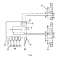
- the introduction and discharge of the pressurized gas via the first opening (14) and the second opening (15) of the hand cylinder (2) is controlled by a 5-port 3-position pressure-center hand solenoid valve (34) as shown in Fig. 4 .
- a stopper mechanism (35) of the present embodiment is hereinafter described in detail.
- a casing (37) is arranged above the hand cylinder (2) of the rack and pinion mechanism (1).
- a cavity (36) is formed in the center, and a stopper cylinder (42) is formed separated from the cavity (36) by a partition (44).
- the cavity (36) accommodates the upper end of the penetrating axis (16) protruding from the hand cylinder (2), and a stopper gear (41) is secured by a screw (40) on the protruding portion of the penetrating axis (16).
- a stopper body (49) in a wedge shape is arranged facing the stopper gear (41) to be able to control the rotation of the penetrating axis (16).
- the stopper body (49) is connected to a stopper piston (47) via a protruding rod (48).
- the stopper piston (47) is slidably arranged in the stopper cylinder (42).
- a connection material (51) is placed on the stopper cylinder (42), and a second stopper opening (52) enabling the introduction and discharge of the pressurized gas is arranged on the connection material (51).
- a first stopper opening (53) is arranged between the stopper piston (47) and the partition (44).
- the introduction and discharge of the pressurized gas to and from the stopper cylinder (42) is controlled by a 5-port 2-position stopper solenoid valve (54).
- the stopper mechanism (35) has a control device, not shown, capable of controlling the stopper gear (41).
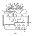
- a sensor mechanism (55) of the present embodiment is hereinafter described in detail. As shown in Fig. 1 , a plate-shaped sensor plate (56) is secured to the front of the hand cylinder (2) of the rack and pinion mechanism (1). An elongated hole (57) is continuously formed from one end to the other end of the sensor plate (5) in a direction parallel to a moving direction of finger body (27), (28).
- sensors (58) spaced apart from each other are arranged in series on the sensor plate (56) to face the inner portion of a widthwise moving direction of the finger bodies (27), (28).
- the sensors (58) have engaging projections, not shown, on the back surfaces thereof to be able to engage width the elongated hole (57) of the sensor plate (56).
- Each of the sensors (58) has its engaging projection engage with the elongated hole (57) of the sensor plate (56) to be movably secured to and detachably from the sensor plate (56).
- the sensors (58) can be attached to arbitrary positions of the elongated hole (57), and the sensors (58) once attached to the sensor plate (56) can also be moved to other positions.
- Each of the sensors (58) is substantially rectangular parallelepiped, and has a detection lamp (60), arranged on the lower end of the front surface thereof, that illuminates to inform operators that the sensor is ready to perform detection, and each of the sensors (58) further has a detection body (61) on the back surface thereof. As shown in Fig. 5 , a detection object (62) that can be detected by the detection body (61) is arranged on the finger body (27), such that the detection body (61) can detect the position of the finger body (27).
- the detection body (61) of the sensor (58) being in a state ready for detection can detect the detection object (62), that is, the detection body (61) of the sensor (58) not in a state ready for detection cannot detect the detection object (62) even if the detection object (62) comes close to the detection body (58).
- the four pieces of the sensor (58) are attached on the sensor plate (56).
- the four pieces of the sensors (58) are respectively referred to as a first sensor (63), a second sensor (64), a third sensor (65), and a fourth sensor (66) from left to right in Fig. 1 .
- Steps for engaging the first to forth sensors (63), (64), (65), and (66) with the elongated hole (57) are hereinafter described.
- the first sensor (63) is first described herein. An operator confirms the maximum open position of the finger body (27) having the detection object (62), and the first sensor (63) is made to engage with the elongated hole (57) of the sensor plate (56) at a position facing this maximum open position. Thus, for example, where the finger bodies (27), (28) slide to the maximum open position with the first sensor (63) being in a state ready for detection, the first sensor (63) detects the detection object (62) of the finger body (27) at the maximum open position.
- the fourth sensor (66) is described hereinafter.
- the operator confirms a closed end position at which the pair of finger bodies (27), (28) is closest to each other upon sliding inwardly, and the forth sensor (66) is made to engage with the elongated hole (57) of the sensor plate (56) at a position facing this closed end position.
- the fourth sensor (66) detects the detection object (62) of the finger body (27) at the closed end position.
- the remaining two pieces namely, the second sensor (64) and the third sensor (65) are arranged on the sensor plate (56).
- the external diameters of the multiple work pieces (67) are previously measured, and the operator confirms a position at which the chucks (32), (33) of the finger bodies (27), (28) form the standby open clearance slightly wider than the external diameter of the workpiece (67) to be gripped.
- the second sensor (64) and the third sensor (65) are arranged spaced apart from each other between the first sensor (63) and the fourth sensor (66) to face the two positions forming the standby open clearances.
- a position forming the maximum open clearance can also be used as the position forming the standby open clearance, where the external diameter of the work piece (67) is wide.
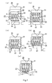
- the detection lamp (60) of the second sensor (64) illuminates as shown in Fig. 6(b) .
- the pair of the finger bodies (27), (28) are previously arranged at the maximum open position, and the stopper gear (41) and the stopper body (49) of the stopper mechanism (35) are made not engage with each other.
- the hand solenoid valve (34) is switched to introduce the pressurized gas via the first opening (15) on a side of the sealing wall (5) in contact with the hand piston (10) and discharge the pressurized gas existing between the hand piston (8) and the sealing wall (4) via the second opening (14).
- the pair of the hand pistons (8), (10) slides in a direction of pressure of the pressurized gas to cause the connection rod (12) to slide in the same direction as the movement of the hand pistons (8), (10), and thereby, the driving rack gear (11) makes the penetrating axis (16) rotate in a clockwise direction with the driving pinion gear (20) to cause the driven pinion gear (21) to rotate in the same direction as the rotation of the penetrating axis (16).
- the rotation of the driven pinion gear (21) makes each of the pair of the driven rack gears (30), (31) move inwardly to cause each of the pair of the finger bodies (27), (28) having the driven rack gears (30), (31) arranged thereon to move inwardly along the guides (23), (24).
- the rolling-element endless circulation linear guides (25), (26) connected to the pair of the finger bodies (27), (28) prevents galling, micro slip, and the like, thus enabling the finger bodies (27), (28) to smoothly slide.
- the detection object (62) on the finger body (27) moves inwardly.
- the detection body (61) on the second sensor (64) detects the detection object (62) and transmits a signal to the control device of the stopper mechanism (35).
- the stopper solenoid valve (54) of the stopper mechanism (35) is switched to discharge the pressurized gas via the first stopper opening (53) at the side of the partition (44) of the stopper cylinder (42) and introduce the pressurized gas via the second opening (52) at the side of the connection material (51).
- the pressurized gas presses and slides the stopper piston (47) from the side of the connection material (51) toward the side of the partition (44).
- This slide of the stopper piston (47) causes the stopper body (49) engage with the stopper gear (41).
- the hand solenoid valve (54) when the hand solenoid valve (54) is switched to activate the stopper mechanism (35), the hand solenoid valve (34) of the rack and pinion mechanism (1) is simultaneously switched to the pressure center.
- the pressurized gas is introduced from both the first opening (14) and the second opening (15) of the hand cylinder (2), so that the pressurized gas exists on both sides of the hand pistons (8), (10).
- the pressurized gas enables the hand pistons (8), (10) to slide slowly. That is, when the hand solenoid valve (34) is switched, the hand pistons (8), (10) do not slide rapidly, and thus, the hand pistons (8), (10) and the sealing walls (4), (5) are prevented from being damaged by the collision of the hand pistons (8), (10) with the sealing walls (4), (5).
- the robot hand moves in a direction of the targeted work piece (67) with the pair of the finger bodies (27), (28) halted and forming the standby open clearance slightly wider than the external diameter of the workpiece (67) as described above. Then, as described in Fig. 6(c) , the chucks (32), (33) of the finger bodies (27), (28) are placed in clearances between the targeted workpiece (67) and the workpieces (67) adjacent to both sides of the targeted workpiece (67) so that the targeted workpiece (67) is positioned between the chucks (32), (33).
- the finger bodies (27), (28) can be prevented from coming in contact with the workpieces (67) adjacent to both sides of the targeted workpiece (67) because the standby open clearance of the pair of finger bodies (27), (28) is set narrower than the maximum open position and slightly wider than the external diameter of the targeted workpiece.
- the targeted work piece (67) can be easily positioned between the chucks (32), (33).
- the stopper solenoid valve (54) is switched to release the engagement between the stopper body (49) and the stopper gear (41) of the stopper mechanism (35), and the hand solenoid valve (34) is switched from the pressure center back to normal condition. Accordingly, the rack and pinion mechanism (1) is activated, and the pair of the finger bodies (27), (28) slides further inwardly from the position forming the standby open clearance.
- the chucks (32), (33) of the finger bodies (27), (28) come in contact with the targeted workpiece (67).
- the chucks (32), (33) try to continue to slide further inwardly after coming in contact with both sides of the targeted workpiece (67), that is, the sliding force is applied to both sides of the workpiece (67) via the chucks (32), (33).
- the chucks (32), (33) can apply a sandwiching force to the workpiece (67), and can grip the workpiece (67).
- the chucks (32), (33) of the finger bodies (27), (28) grip the targeted workpiece (67). Then, as shown in Fig. 6(e) , the robot hand is pulled upward, so that the targeted workpiece (67) can be moved to a destination. Then, after the targeted workpiece (67) is moved to the destination, the hand solenoid valve (34) is switched to move the pair of the finger bodies (27), (28) in directions away from each other.
- the hand solenoid valve (34) is first switched to discharge the pressurized gas via the first opening (15), via which the pressurized gas is introduced into the hand cylinder (2) when the finger bodies (27), (28) slide inwardly, and introduce the pressurized gas via the second opening (14) opposite to the first opening (15).
- the pair of the hand pistons (8), (10) slide in the opposite direction to cause the penetrating axis (16) to rotate in the opposite direction.
- the driven pinion gear rotates in the opposite direction to cause the pair of the finger bodies (27), (28) arranged with the driven rack gears (30), (31) to move in directions away from each other.
- the movement of the finger bodies (27), (28) in directions away from each other releases the workpiece sandwiched by the chucks (32), (33), and thus, the transfer of the targeted workpiece (67) finishes.
- the pair of the finger bodies (27), (28) slide inwardly to the closed end position near the center in the widthwise direction of the hand cylinder (2) as shown in Fig 7(e) , and the fourth sensor (66) detects the position of the finger bodies (27), (28) to halt operation of the rack and pinion mechanism (1).
- the computer switches the ready-for-detection sensor from the second sensor (64) to the first sensor (63). Accordingly, the detection lamp (60) of the first sensor (63) illuminates as shown in Fig. 7(a)(b) , and the finger bodies (27), (28) form the standby open clearance at the maximum open position.
- the finger bodies (27), (28) form the standby open clearance at the open position more outward than the position forming the standby open clearance when the second sensor (64) is activated, thus capable of forming the standby open clearance wider than that when the second sensor (64) is activated. Therefore, as shown in Fig. 7(c) (d) , the workpiece (67) having a larger external diameter can be gripped.
- the computer switches the ready-for-detection sensor to the third sensor (65). Accordingly, the detection lamp (60) of the third sensor (65) illuminates as shown in Fig. 8(a)(b) , and the finger bodies (27), (28) form the standby open clearance at the position of the third sensor (65) more inward than the position of the second sensor (64). Therefore, the finger bodies (27), (28) can form the standby open clearance narrower than that when the second sensor (64) is activated.
- the workpiece (67) having a smaller external diameter can be gripped without being interfered by other workpieces (67).
- the robot hand of the present invention can easily and rapidly change the standby open clearance with only one pair of the finger bodies (27), (28) only by operation of the computer to switch the ready-for-detection sensor without replacing the finger bodies (27), (28) of the robot hand.
- the robot hand of the present invention does not require troublesome adjustment of the standby open clearance every time gripping the workpiece of another size, and can rapidly consecutively form the standby open clearance appropriate for each of multiple workpieces (67) in various external diameters, thus improving the workability when consecutively or randomly transporting multiple workpieces (67) in various external diameters.
Landscapes
- Engineering & Computer Science (AREA)
- Robotics (AREA)
- Mechanical Engineering (AREA)
- Human Computer Interaction (AREA)
- Manipulator (AREA)
Applications Claiming Priority (2)
| Application Number | Priority Date | Filing Date | Title |
|---|---|---|---|
| JP2007035834A JP4726241B2 (ja) | 2007-02-16 | 2007-02-16 | 産業用ロボットのロボットハンド |
| PCT/JP2007/065838 WO2008099525A1 (fr) | 2007-02-16 | 2007-08-14 | Main de robot d'un robot industriel |
Publications (2)
| Publication Number | Publication Date |
|---|---|
| EP2113345A1 true EP2113345A1 (fr) | 2009-11-04 |
| EP2113345A4 EP2113345A4 (fr) | 2010-07-21 |
Family
ID=39689782
Family Applications (1)
| Application Number | Title | Priority Date | Filing Date |
|---|---|---|---|
| EP07792481A Withdrawn EP2113345A4 (fr) | 2007-02-16 | 2007-08-14 | Main de robot d'un robot industriel |
Country Status (6)
| Country | Link |
|---|---|
| US (1) | US20100131100A1 (fr) |
| EP (1) | EP2113345A4 (fr) |
| JP (1) | JP4726241B2 (fr) |
| KR (1) | KR20100013353A (fr) |
| CN (1) | CN101378884B (fr) |
| WO (1) | WO2008099525A1 (fr) |
Cited By (1)
| Publication number | Priority date | Publication date | Assignee | Title |
|---|---|---|---|---|
| CN107234630A (zh) * | 2017-05-18 | 2017-10-10 | 杭州新松机器人自动化有限公司 | 一种工业机器人腕部齿轮侧隙的调整结构及其使用方法 |
Families Citing this family (12)
| Publication number | Priority date | Publication date | Assignee | Title |
|---|---|---|---|---|
| JP5306948B2 (ja) * | 2009-09-10 | 2013-10-02 | 本田技研工業株式会社 | マニプレータ装置 |
| JP5459711B2 (ja) * | 2010-06-04 | 2014-04-02 | 日本スピンドル製造株式会社 | 食品の搬送装置 |
| JP5064534B2 (ja) * | 2010-06-14 | 2012-10-31 | 株式会社豊電子工業 | ハンド装置及び多関節ロボット |
| TWI405650B (zh) * | 2010-12-24 | 2013-08-21 | Univ Nat Taiwan Science Tech | 機器人系統及利用該機器人系統彈奏和弦的方法 |
| US10617049B2 (en) * | 2014-01-17 | 2020-04-07 | Fuji Corporation | Component mounting device and gripping members |
| JP2018001281A (ja) | 2016-06-27 | 2018-01-11 | 株式会社デンソーウェーブ | ロボットハンド |
| JP6876476B2 (ja) | 2017-03-17 | 2021-05-26 | 株式会社東芝 | 保持機構、移載装置及びハンドリングロボットシステム |
| CN110842974A (zh) * | 2019-11-22 | 2020-02-28 | 长沙市奥思得精工模具有限公司 | 一种汽车夹具识别机构 |
| JP7406459B2 (ja) * | 2020-06-05 | 2023-12-27 | オークマ株式会社 | グリッパ装置 |
| CN113247613A (zh) * | 2021-05-24 | 2021-08-13 | 三门峡职业技术学院 | 一种自动化取料机械手 |
| CN114147751A (zh) * | 2021-12-29 | 2022-03-08 | 安图实验仪器(郑州)有限公司 | 试管尺寸信息识别抓手装置 |
| CN115922767B (zh) * | 2022-12-03 | 2025-02-07 | 陕西德源府谷能源有限公司 | 一种操作巡检机器人故障缺陷检测识别模块夹持机构 |
Family Cites Families (24)
| Publication number | Priority date | Publication date | Assignee | Title |
|---|---|---|---|---|
| US3760956A (en) * | 1971-08-23 | 1973-09-25 | Burch Controls Inc | Industrial robot |
| SE416452B (sv) * | 1975-06-16 | 1981-01-05 | Asea Ab | Industrirobot |
| DE2823584C2 (de) * | 1978-05-30 | 1983-01-27 | Pfaff Industriemaschinen Gmbh, 6750 Kaiserslautern | Greifvorrichtung für Industrieroboter |
| DE2937061C2 (de) * | 1979-09-13 | 1981-11-12 | Pfaff Industriemaschinen Gmbh, 6750 Kaiserslautern | Handhabungsgerät mit einer Greifvorrichtung |
| JPS59353B2 (ja) * | 1980-07-24 | 1984-01-06 | ファナック株式会社 | 把持装置 |
| US4379335A (en) * | 1980-10-28 | 1983-04-05 | Auto-Place, Inc. | Electronic controller and portable programmer system for a pneumatically-powered point-to-point robot |
| US4545722A (en) * | 1983-05-04 | 1985-10-08 | Westinghouse Electric Corp. | Flexible robot gripper for irregular shapes |
| DE3513648A1 (de) * | 1985-04-16 | 1986-10-23 | Rudi 4018 Langenfeld Kirst | Greifvorrichtung fuer werkstuecke oder sonstige handhabungsteile |
| FR2589770B1 (fr) * | 1985-11-07 | 1988-03-11 | Normandie Ste Indle Basse | Dispositif perfectionne de pince ou main de robot. |
| US4699414A (en) * | 1986-04-21 | 1987-10-13 | The United States Of America As Represented By The Secretary Of The Air Force | Multi use gripper for industrial robot |
| US4728137A (en) * | 1986-07-22 | 1988-03-01 | American Engineering And Trade, Inc. | Compound toggle robotic gripper |
| JP2794634B2 (ja) * | 1989-08-25 | 1998-09-10 | ファナック株式会社 | プリント板の製造方法及び吸着ハンド |
| JP2518630Y2 (ja) * | 1989-12-12 | 1996-11-27 | 高野ベアリング 株式会社 | 平行開閉チャック装置 |
| JP2570041B2 (ja) * | 1991-12-27 | 1997-01-08 | 株式会社栗本鐵工所 | メカニカルハンド |
| DE4397414T1 (de) * | 1993-06-02 | 1996-05-09 | Yaskawa Denki Kitakyushu Kk | Hydraulische Quelle und hydraulische Maschine |
| US5984623A (en) * | 1998-03-31 | 1999-11-16 | Abb Flexible Automation, Inc. | Carrier feed vaccum gripper |
| NL1010446C2 (nl) * | 1998-11-02 | 2000-05-03 | Exact Dynamics B V | Manipulator. |
| JP3737331B2 (ja) * | 1999-03-31 | 2006-01-18 | Spsシンテックス株式会社 | 粉体の自動充填方法及び装置 |
| CN1170659C (zh) * | 2000-10-24 | 2004-10-13 | 中国科学院合肥智能机械研究所 | 一种多传感器机器人手爪 |
| US6666489B2 (en) * | 2001-08-23 | 2003-12-23 | Btm Corporation | Sealed gripper apparatus |
| WO2004028753A2 (fr) * | 2002-09-26 | 2004-04-08 | Barrett Technology, Inc. | Main robotique autonome, intelligente |
| JP3905075B2 (ja) * | 2003-11-17 | 2007-04-18 | ファナック株式会社 | 作業プログラム作成装置 |
| US7181314B2 (en) * | 2003-11-24 | 2007-02-20 | Abb Research Ltd. | Industrial robot with controlled flexibility and simulated force for automated assembly |
| US9110456B2 (en) * | 2004-09-08 | 2015-08-18 | Abb Research Ltd. | Robotic machining with a flexible manipulator |
-
2007
- 2007-02-16 JP JP2007035834A patent/JP4726241B2/ja active Active
- 2007-08-14 KR KR1020077028668A patent/KR20100013353A/ko not_active Withdrawn
- 2007-08-14 US US11/989,355 patent/US20100131100A1/en not_active Abandoned
- 2007-08-14 EP EP07792481A patent/EP2113345A4/fr not_active Withdrawn
- 2007-08-14 CN CN2007800006665A patent/CN101378884B/zh not_active Expired - Fee Related
- 2007-08-14 WO PCT/JP2007/065838 patent/WO2008099525A1/fr not_active Ceased
Cited By (2)
| Publication number | Priority date | Publication date | Assignee | Title |
|---|---|---|---|---|
| CN107234630A (zh) * | 2017-05-18 | 2017-10-10 | 杭州新松机器人自动化有限公司 | 一种工业机器人腕部齿轮侧隙的调整结构及其使用方法 |
| CN107234630B (zh) * | 2017-05-18 | 2019-07-23 | 杭州新松机器人自动化有限公司 | 一种工业机器人腕部齿轮侧隙的调整结构及其使用方法 |
Also Published As
| Publication number | Publication date |
|---|---|
| JP4726241B2 (ja) | 2011-07-20 |
| EP2113345A4 (fr) | 2010-07-21 |
| CN101378884B (zh) | 2011-07-20 |
| US20100131100A1 (en) | 2010-05-27 |
| CN101378884A (zh) | 2009-03-04 |
| WO2008099525A1 (fr) | 2008-08-21 |
| KR20100013353A (ko) | 2010-02-10 |
| JP2008200759A (ja) | 2008-09-04 |
Similar Documents
| Publication | Publication Date | Title |
|---|---|---|
| EP2113345A1 (fr) | Main de robot d'un robot industriel | |
| KR101761760B1 (ko) | 유체압 실린더 | |
| EP0450538B1 (fr) | Appareil diviseur | |
| TWI639492B (zh) | 開閉夾頭 | |
| CN113752292B (zh) | 夹持装置 | |
| US10012575B2 (en) | Specimen holder with actuation unit | |
| US6666489B2 (en) | Sealed gripper apparatus | |
| JP7448739B2 (ja) | チャック装置の駆動システム及びその制御方法 | |
| CA2154817C (fr) | Mecanisme de prehension hydraulique | |
| CA2615364A1 (fr) | Prehenseur de robot industriel | |
| JP2009172735A (ja) | 産業用ロボットのハンド装置 | |
| KR20180080296A (ko) | 펀칭 장치 | |
| US4752094A (en) | Robot gripper or hand device | |
| US6397728B1 (en) | Linear stopping and positioning apparatus | |
| CN119526450A (zh) | 电动气动夹持器 | |
| EP3666413A1 (fr) | Procédé et appareil pour faire avancer des produits devant être formés | |
| JP2528157Y2 (ja) | 動作検出機構を備えた平行開閉チャック | |
| US20250229383A1 (en) | Device for clamping workpieces on machine tools | |
| JP2008272878A (ja) | 把持装置 | |
| JP2022147704A (ja) | 物品検査装置 | |
| JPH0355264B2 (fr) | ||
| RU61619U1 (ru) | Станок агрегатный | |
| JP2025040362A (ja) | クランプ装置 | |
| JP2007326177A (ja) | 把持装置 | |
| JP2005297086A (ja) | 産業用ロボットチャック |
Legal Events
| Date | Code | Title | Description |
|---|---|---|---|
| PUAI | Public reference made under article 153(3) epc to a published international application that has entered the european phase |
Free format text: ORIGINAL CODE: 0009012 |
|
| 17P | Request for examination filed |
Effective date: 20090916 |
|
| AK | Designated contracting states |
Kind code of ref document: A1 Designated state(s): AT BE BG CH CY CZ DE DK EE ES FI FR GB GR HU IE IS IT LI LT LU LV MC MT NL PL PT RO SE SI SK TR |
|
| DAX | Request for extension of the european patent (deleted) | ||
| A4 | Supplementary search report drawn up and despatched |
Effective date: 20100618 |
|
| RAP1 | Party data changed (applicant data changed or rights of an application transferred) |
Owner name: SCHUNK INTEC K.K |
|
| GRAP | Despatch of communication of intention to grant a patent |
Free format text: ORIGINAL CODE: EPIDOSNIGR1 |
|
| RIC1 | Information provided on ipc code assigned before grant |
Ipc: B25J 15/08 20060101AFI20100907BHEP |
|
| STAA | Information on the status of an ep patent application or granted ep patent |
Free format text: STATUS: THE APPLICATION IS DEEMED TO BE WITHDRAWN |
|
| 18D | Application deemed to be withdrawn |
Effective date: 20110225 |