EP2113347A1 - Couteau divisé pour un arbre de mesure inférieur dans une machine de coupe longitudinale - Google Patents
Couteau divisé pour un arbre de mesure inférieur dans une machine de coupe longitudinale Download PDFInfo
- Publication number
- EP2113347A1 EP2113347A1 EP08155576A EP08155576A EP2113347A1 EP 2113347 A1 EP2113347 A1 EP 2113347A1 EP 08155576 A EP08155576 A EP 08155576A EP 08155576 A EP08155576 A EP 08155576A EP 2113347 A1 EP2113347 A1 EP 2113347A1
- Authority
- EP
- European Patent Office
- Prior art keywords
- connecting piece
- opening
- knife
- ring
- ring segment
- Prior art date
- Legal status (The legal status is an assumption and is not a legal conclusion. Google has not performed a legal analysis and makes no representation as to the accuracy of the status listed.)
- Granted
Links
Images




Classifications
-
- B—PERFORMING OPERATIONS; TRANSPORTING
- B26—HAND CUTTING TOOLS; CUTTING; SEVERING
- B26D—CUTTING; DETAILS COMMON TO MACHINES FOR PERFORATING, PUNCHING, CUTTING-OUT, STAMPING-OUT OR SEVERING
- B26D7/00—Details of apparatus for cutting, cutting-out, stamping-out, punching, perforating, or severing by means other than cutting
- B26D7/26—Means for mounting or adjusting the cutting member; Means for adjusting the stroke of the cutting member
- B26D7/2614—Means for mounting the cutting member
- B26D7/2621—Means for mounting the cutting member for circular cutters
-
- B—PERFORMING OPERATIONS; TRANSPORTING
- B26—HAND CUTTING TOOLS; CUTTING; SEVERING
- B26D—CUTTING; DETAILS COMMON TO MACHINES FOR PERFORATING, PUNCHING, CUTTING-OUT, STAMPING-OUT OR SEVERING
- B26D1/00—Cutting through work characterised by the nature or movement of the cutting member or particular materials not otherwise provided for; Apparatus or machines therefor; Cutting members therefor
- B26D1/0006—Cutting members therefor
-
- B—PERFORMING OPERATIONS; TRANSPORTING
- B26—HAND CUTTING TOOLS; CUTTING; SEVERING
- B26D—CUTTING; DETAILS COMMON TO MACHINES FOR PERFORATING, PUNCHING, CUTTING-OUT, STAMPING-OUT OR SEVERING
- B26D1/00—Cutting through work characterised by the nature or movement of the cutting member or particular materials not otherwise provided for; Apparatus or machines therefor; Cutting members therefor
- B26D1/0006—Cutting members therefor
- B26D2001/0046—Cutting members therefor rotating continuously about an axis perpendicular to the edge
Definitions
- the invention relates to a split blade for a lower blade shaft in a longitudinal cutting machine, which comprises at least two ring segments, which are dimensioned so that they can together enclose the lower blade shaft. Furthermore, the invention relates to a lower blade shaft for a longitudinal cutting machine with at least one split knife mounted thereon and to a longitudinal cutting machine with a lower blade shaft and at least one split knife mounted thereon.
- Roll cutting machines or slitting machines are known from the prior art. They each comprise an upper cutter shaft with upper blades mounted thereon and a lower cutter shaft with lower blades mounted thereon. The lower blade and the upper blade face each other and cut the material to be cut. Different types of knives for lower knives and upper knives are known, for example, a lower knives may be grooving knives or cutting rings.
- divisible or split knives in particular divisible lower knives on the lower knife shaft.
- the divided lower blades are generally annular knives, which are composed of two ring segments.
- the provision of a split knife facilitates a possible replacement of knives with built-in shaft.
- the split blades are made or ground in a composite, that is ring-shaped state. It has been found that only grinding in the closed annular state provides the necessary accuracy guaranteed for the cut. Subsequently, the split knife thus produced is broken down into its two ring segments and mounted on the lower shaft and thereby reassembled.
- a split ring cutter is known.
- the split knives disclosed therein can be broken down into two ring segments.
- the ring segments can be joined together again by the provision of different forms by positive engagement. It is possible to use different shapes for different rings, so that they can be safely distinguished from each other during assembly.
- the split ring cutter according to the DE 203 18 561 U1 but has the disadvantage that the production of the elements for the positive connection is extremely difficult. It often comes to an over-determination of the position and tension. These can lead to problems in view of the required accuracy for the alignment of the abutting surfaces of about 0 to 0.001 mm. It is also possible that when disassembling or mounting the annular segments, the cut edges are damaged.
- a ring for the lower knife shaft in longitudinal cutting machines is known. It is a ring that can be split into two parts. The two halves are mounted with two wedge connections offset by 90 ° with low backlash. It is difficult to ensure the required accuracy in the production of the ring segments. Furthermore, by the EP 0 239 657 B1 also the problem of damage during assembly or disassembly not overcome.
- the invention has the advantage that ring segments can be connected to each other exactly, in particular, the ring segments can be aligned axially and radially exactly.
- Another advantage according to the invention is that no damage to the ring segments in the connection and separation area occur when connecting and disconnecting the ring segments.
- Another advantage of the invention is that no damage to the upper blade can be caused by the precisely positioned and ground lower blade, especially not if the upper blade consists of brittle carbide.
- the invention relates to a split blade for a lower blade shaft in a longitudinal cutting machine, comprising at least two ring segments, which are dimensioned so that they can together enclose the lower blade shaft. However, it can also be provided more than two ring segments. Joined together, the at least two ring segments are circular. Preferably, the ring segments have an extension in the axial direction of the lower blade shaft, at most in the range of about 10 to 200 mm, preferably in the range 20 to 50 mm.
- the first ring segment has a connecting piece, and the second ring segment has an opening for receiving the connecting piece.
- the connector may be formed in one or more pieces, it may consist of a material or of different materials.
- the connecting portion refers to that portion where contact between the connecting piece and the opening occurs upon receiving the connecting piece in the opening.
- the entire connecting region of either the connecting piece or the opening forming portion is made of an elastically deformable or elastically deformable material, but it is also possible that the entire connection area between the connecting piece and the area forming the opening an elastically deformable or elastically deformable deformable material is made.
- the ring segments of the split knife are abutted against each other when placed on the lower knife shaft adjacent abutting edges by means of the cone-shaped connecting piece frictionally connected to each other.
- the connecting piece and / or the area forming the opening is wholly or partially rotationally symmetrical.
- the connecting piece and / or the associated region forming the opening is at least partially conical and / or at least partially in the form of a spherical segment.
- a spherical area it is possible for a spherical area to be adjoined by a conical area, this applies both to the connecting piece and to the area forming the opening.
- a cylindrical section to adjoin the conical section, for example. It is also possible to combine a spherical section with a cylindrical section.
- the connecting piece may be conical or frusto-conical in shape, it may be formed completely or partially conical.
- the cone-shaped connecting piece can be made compact or at least partially hollow.
- the opening forming region which is adapted to receive the cone-shaped connecting piece.
- the connecting piece may be hemispherical or otherwise designed as a spherical segment. It may be wholly or partially spherical segment-shaped, it may be compact or at least partially hollow. The same applies to the opening forming region which receives the spherical segment-shaped connector.
- the connecting piece on the side facing the opening is at least partially hollow, so that the outer region of the connecting piece is at least partially inwardly elastically deformable when forming the frictional connection.
- the outer region of the connecting piece while the outer wall of the connecting piece is meant, hence the area which receives the frictional connection with the area forming the opening. That the outer portion of the connecting piece is elastically deformable inwardly means that the deformation takes place in the direction of the central axis of the connecting piece.
- the hollow region is in turn formed conical, so that the outer region of the connecting piece is designed in the form of a circumferential cone-shaped web.
- the area forming the opening includes a portion projecting freely toward the connector, so that the portion forming the opening is deformable outwardly in forming the frictional connection.
- Deformable in this case means that the deformation takes place away from the axis / axis of symmetry of the connecting piece or the opening.
- the inner surface of the free-standing portion may have the shape of a spherical surface or the shape of a cone. This towering area is adapted in shape to the shape of the associated connector.
- the cone of the cone-shaped connecting piece or the cone of the conical opening tapers in the direction of the first ring segment towards the second ring segment and / or the diameter of the spherical segment-shaped connecting piece or the diameter of the spherical segment-shaped opening decreases in the direction of first ring segment towards the second ring segment.
- the inclination angle of the intended cone is very small, that is, the conical structure is not much different from a cylindrical shape.
- the angle of inclination ⁇ of the cone is less than or equal to 5 °.
- the inclination angle ⁇ denotes the angle by which the lateral surface is inclined relative to the lateral surface of a cylinder (compare also FIG. 1 ).
- the connecting piece protrudes beyond the abutting edge of the first ring segment, so that the abutting edges of the ring segments are spaced apart as long as the elastically deformable material is not deformed when connecting the ring segments.
- the connector serves in this regard as a spacer between the ring segments and their abutting edges. Only at a deformation of the elastically deformable material when connecting the ring segments on the connector, the abutting edges of the ring segments approach each other, that is, only when an additional force is applied to the elastically deformable material.
- the relation 0.4 mm ⁇ d ⁇ 0.5 mm applies.
- This distance is considered sufficient, on the one hand to ensure a good pre-positioning of the ring segments to each other and on the other hand to ensure a sufficient distance between the ring segments in the pre-positioning, so that the abutting edges of the ring segments are not damaged during assembly.
- the distance d is preferably in the form of a slit, wherein the gap preferably has a constant width along the abutting edge.
- the split knife on a fastening means which engages in the connector and which is formed so that the fastening means when connecting the ring segments pushes the connector of the first ring segment in the associated opening of the second ring segment or pulls into, wherein the elastically deformable material is deformed, so that the abutting edges of the ring segments to move towards each other.
- the connector has a cavity for receiving the fastener therein. Preferably, this cavity is adapted in its dimensions to the fastener. The pushing in or pulling in of the connecting piece into the associated opening involves two alternative forms, such as the connection under deformation of the elastically deformable material.
- connection by pushing or pulling depends on which fastener is used, and where this fastener is fixed or from where (in particular from which ring segment) it attacks for attachment.
- this fastener is fixed or from where (in particular from which ring segment) it attacks for attachment.
- the fastening means is integrally formed, but it may also be formed in several pieces. According to a particularly preferred embodiment, the fastening means comprises a screw.
- the elastically deformable or deformed material relaxes one another, and the ring segments are forced apart by the deformation energy released.
- This separation forces each other when loosening the ring segments of each other instantaneously and supports the release of the ring segments from the beginning of each other. This avoids that when loosening the ring segments an unwanted contact between the ring segments results, which could lead to damage to the ring segments.
- the connecting piece is pressed or glued into the first ring segment.
- Other types of connection between connector and first ring segment are possible.
- the split knife has securing means for securing the fastener against falling out upon disassembly or mounting of the split knife on the lower knife shaft. This prevents unwanted service life and caused by falling out of the fastener further damage to other components of a machine, such as a slitter.
- a ring segment has an opening in an outer peripheral area to receive the fastener.
- a screw is inserted as a fastening means in the ring segment and screwed by such an opening.
- the opening itself can have any desired shape, in particular it can have a circular cutout or an elliptical cutout.
- two ring segments with a plurality, preferably two, connecting pieces and the associated openings are interconnected.
- this relates to a bedknife shaft for a slitter with at least one split knife mounted thereon.
- the lower blade may be different types of knives, such as cutting rings or grooving knives.
- the split knife can have all the properties as described in the first aspect of the invention concerning a split knife.
- this relates to a slitter with a lower knife shaft and at least one split knife mounted thereon.
- the split knife may have all the features of the split knife, as described above in the first aspect of the invention concerning a split knife.
- Fig. 1 shows a schematic diagram for explaining the operation of the invention. Shown is a section of a first ring segment 2 and a section of a second ring segment 3. The two ring segments each have a joint edge 4 and 5 respectively. The abutting edges 4 and 5 are spaced from each other by the distance d.
- the connecting piece 1 is fixedly connected to the first ring segment 2.
- the cone-shaped connecting piece has an angle of inclination ⁇ against an axis C, the axis C being parallel to the axis of symmetry A of the connecting piece and the conical opening. Shown is a state in which the cone-shaped connector is inserted into the cone-shaped opening, without already a deformation of the elastically deformable material would have taken place. It is possible that there is either the cone-shaped connector at least partially made of an elastically deformable material, and / or that the cone-shaped opening forming portion of the second ring segment consists at least partially of an elastically deformable material. In any case, the elastically deformable material is at least partially present in the connecting region between the cone-shaped connecting piece and the associated conical opening.
- the cone-shaped connecting piece is deformed or squeezed in a further insertion of the cone-shaped connecting piece in the cone-shaped opening along the direction of movement B.
- an additional force is spent.
- the application of this additional force to the deformation is controlled, for example by attaching a fastener (not shown) in the cone-shaped connector and the opening, so that slowly and controlled the abutment surfaces 4 and 5 of the first and second ring segments 2 and 3 toward each other move until the distance d between inside is 0. This can be successfully prevented be damaged that the abutting edges during assembly.
- the use of the cone guarantees a precise alignment.
- the region which forms the cone-shaped opening is at least partially provided with an elastically deformable material.
- the elastically deformable portion of the opening-forming portion is deformed (in view of FIG FIG. 1 pushed outward).
- the effect is in principle the same as described above, when the cone-shaped connecting piece has the elastically deformable material.
- the safe assembly and disassembly of the ring segments can be ensured, and by the use of the cone exact flight conditions are created.
- FIG. 2 shows a sectional view through a split knife and a detailed representation thereof. Shown are the first ring segment 2 and the second ring segment 3, wherein it is in the present case in the first ring segment to an upper blade half and the second ring segment is a lower blade half.
- the first ring segment has an opening 12 for a fastening means 8 which is inserted into a cone-shaped connecting piece 1 or into the cone-shaped opening of the second ring segment 3.
- the conical connecting piece 1 is in the present example only partially conical, in particular it is conical in the connecting region between the first ring segment and the second ring segment 2 and 3. Adjacent to the conical portion of the conical connecting piece 1 is a cylindrical portion 1 b.
- the cone-shaped connecting piece 1 is pressed into the first ring segment 2, but it would also be possible to provide instead of pressing in a gluing of the connecting piece.
- the upper portion 1a of the cone-shaped connecting piece 1 has an opening into which a fastening means 8, here in the form of a screw, is inserted.
- the screw 8 is secured by means of a securing means 9 against accidental falling out.
- the contact area between the first ring segment 2 and the second ring segment 3 can be adjusted extremely accurately according to the invention, in the illustrated embodiment, an accuracy of 0 to 0.001 mm is achieved (indicated by the arrows at reference numeral 10).
- the two ring segments 2 and 3 are connected by two connecting pieces, which in FIG.
- FIG. 3 shows a detailed view of the sectional view according to FIG. 2 , In the enlarged view, the conical region of the cone-shaped connecting piece 1 can be seen better.
- the inclination angle ⁇ of the cone is up to 5 °.
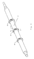
- FIG. 4 shows a perspective view of a lower blade shaft 13 with a plurality of mounted blades 20, 21 and 22.
- the knives 20, 21 and 22 are identical, but they could also differ from each other in design and type.
- Fig. 5 shows a further preferred embodiment of the invention.
- the connecting piece 1 shown is rotationally symmetrical about the axis A and conical. It has a central area and an area located on the side facing the opening. The latter is hollow on the side of the opening.
- the formed cavity 1d has a cone shape.
- the region of the connecting piece 1 facing the opening thereby has an outer region 1c, which is formed circumferentially in the shape of a web. Inner and outer wall surfaces of this area 1c also have a cone shape as a whole.
- the thus designed connector 1 is now inserted into the cone-shaped opening 6. In this case, the outer region 1c elastically inward, that is to be deformed in the direction of the axis A.
- the provision of the cavity 1d in the connector 1 contributes significantly to the resilient properties at the connector. Otherwise, the statements regarding the in Fig. 1 referenced schematic diagram.
- Fig. 6 shows a further embodiment of the invention.
- the rotationally symmetrical connector 1 is composed of a cylindrical upper portion and a spherical segment-shaped lower portion. Again, a cavity 1d is provided in the connector at the opening-facing side. This has the consequence that the lower outer portion 1c of the connecting piece is web-shaped circumferentially.
- the outer surface of the outer region 1c of the connecting piece 1 is formed in the form of a spherical surface.
- the opening-forming portion 6 corresponds to the spherical surface shape of the outer portion 1c of the connecting piece 1.
- Fig. 7 shows a further preferred embodiment of the invention.
- the rotationally symmetrical connecting piece 1 is cone-shaped and integrally formed with the first ring segment.
- the connector is not elastically deformable.
- the opening forming portion 6 is fitted in the form of an extra part 6b in the second ring segment 3.
- the region 6 forming the opening has a freely rising region 6a.
- This is formed rotationally symmetrical about the axis A circumferentially.
- Its inner surface has the shape of a cone.
- the outer surface is formed parallel to the axis A, but it could also be oriented differently.
- a cavity 6c is circumferentially provided between the freely rising portion 6a and the second ring segment 3.
- Fig. 8 shows a further embodiment of the invention. It comprises a connecting piece 1, which is composed of a spherical segment-shaped portion and an adjoining cylindrical portion.
- the connector 1 not deformable.
- On the side of the second ring segment 3 of the opening forming portion 6 is formed by an extra piece 6b.
- this region has a freely rising portion 6a, which is rotationally symmetrical around the axis A web-shaped.
- a part of the inner surface of the upstanding portion 6a is adapted to the spherical surface of the connecting piece 1, that is also formed in the form of a spherical surface.
- the freely rising portion 6a and the second ring segment 3 is again - as well as in Fig.
- the split blade for a lower blade shaft in a longitudinal cutting machine it is possible to align the first ring segment and the second ring segment exactly aligned with each other, including the use of the cone-shaped and / or spherical segment-shaped connector or the associated opening significantly contributes. Furthermore, the use of the elastically deformable material and the frictional connection made possible by the split knife according to the invention makes it possible for no damage to the ring segments or their abutment surfaces and cutting surfaces to occur during assembly or disassembly of the at least two ring segments.
Landscapes
- Life Sciences & Earth Sciences (AREA)
- Forests & Forestry (AREA)
- Engineering & Computer Science (AREA)
- Mechanical Engineering (AREA)
- Nonmetal Cutting Devices (AREA)
- Investigating Or Analyzing Materials Using Thermal Means (AREA)
- Harvester Elements (AREA)
- Details Of Cutting Devices (AREA)
- Polishing Bodies And Polishing Tools (AREA)
Priority Applications (3)
| Application Number | Priority Date | Filing Date | Title |
|---|---|---|---|
| AT08155576T ATE485141T1 (de) | 2008-05-02 | 2008-05-02 | Geteiltes messer für eine untermesswelle in einer längsschneidemaschine |
| EP08155576A EP2113347B1 (fr) | 2008-05-02 | 2008-05-02 | Couteau divisé pour un arbre de mesure inférieur dans une machine de coupe longitudinale |
| DE502008001582T DE502008001582D1 (de) | 2008-05-02 | 2008-05-02 | Geteiltes Messer für eine Untermesswelle in einer Längsschneidemaschine |
Applications Claiming Priority (1)
| Application Number | Priority Date | Filing Date | Title |
|---|---|---|---|
| EP08155576A EP2113347B1 (fr) | 2008-05-02 | 2008-05-02 | Couteau divisé pour un arbre de mesure inférieur dans une machine de coupe longitudinale |
Publications (2)
| Publication Number | Publication Date |
|---|---|
| EP2113347A1 true EP2113347A1 (fr) | 2009-11-04 |
| EP2113347B1 EP2113347B1 (fr) | 2010-10-20 |
Family
ID=39767000
Family Applications (1)
| Application Number | Title | Priority Date | Filing Date |
|---|---|---|---|
| EP08155576A Not-in-force EP2113347B1 (fr) | 2008-05-02 | 2008-05-02 | Couteau divisé pour un arbre de mesure inférieur dans une machine de coupe longitudinale |
Country Status (3)
| Country | Link |
|---|---|
| EP (1) | EP2113347B1 (fr) |
| AT (1) | ATE485141T1 (fr) |
| DE (1) | DE502008001582D1 (fr) |
Citations (7)
| Publication number | Priority date | Publication date | Assignee | Title |
|---|---|---|---|---|
| US2652297A (en) * | 1949-08-19 | 1953-09-15 | Thibault | Fastening device |
| US2666485A (en) * | 1950-06-06 | 1954-01-19 | John G Antosh | Rotary cutter |
| US3246555A (en) * | 1964-09-28 | 1966-04-19 | Rite Size Corrugated Machinery | Tool hub |
| US3850069A (en) * | 1974-01-21 | 1974-11-26 | S & S Corrugated Paper Mach | Mounting of rotary split slitting knives |
| DE2801617A1 (de) * | 1978-01-14 | 1979-07-19 | Wabco Westinghouse Gmbh | Lagerzentrierung von geteilten pleuelstangen |
| EP0239657A1 (fr) * | 1986-04-01 | 1987-10-07 | Dienes Werke Für Maschinenteile Gmbh & Co Kg | Anneau pour une cisaille à couteaux circulaires |
| DE20318561U1 (de) * | 2003-11-27 | 2004-03-11 | Dienes Werke für Maschinenteile GmbH & Co KG | Schneideinrichtung mit geteilten Ringen |
-
2008
- 2008-05-02 AT AT08155576T patent/ATE485141T1/de active
- 2008-05-02 EP EP08155576A patent/EP2113347B1/fr not_active Not-in-force
- 2008-05-02 DE DE502008001582T patent/DE502008001582D1/de active Active
Patent Citations (7)
| Publication number | Priority date | Publication date | Assignee | Title |
|---|---|---|---|---|
| US2652297A (en) * | 1949-08-19 | 1953-09-15 | Thibault | Fastening device |
| US2666485A (en) * | 1950-06-06 | 1954-01-19 | John G Antosh | Rotary cutter |
| US3246555A (en) * | 1964-09-28 | 1966-04-19 | Rite Size Corrugated Machinery | Tool hub |
| US3850069A (en) * | 1974-01-21 | 1974-11-26 | S & S Corrugated Paper Mach | Mounting of rotary split slitting knives |
| DE2801617A1 (de) * | 1978-01-14 | 1979-07-19 | Wabco Westinghouse Gmbh | Lagerzentrierung von geteilten pleuelstangen |
| EP0239657A1 (fr) * | 1986-04-01 | 1987-10-07 | Dienes Werke Für Maschinenteile Gmbh & Co Kg | Anneau pour une cisaille à couteaux circulaires |
| DE20318561U1 (de) * | 2003-11-27 | 2004-03-11 | Dienes Werke für Maschinenteile GmbH & Co KG | Schneideinrichtung mit geteilten Ringen |
Also Published As
| Publication number | Publication date |
|---|---|
| ATE485141T1 (de) | 2010-11-15 |
| EP2113347B1 (fr) | 2010-10-20 |
| DE502008001582D1 (de) | 2010-12-02 |
Similar Documents
| Publication | Publication Date | Title |
|---|---|---|
| EP1053083B1 (fr) | Appareil de granulation comportant un rotor coupant | |
| EP2819815B1 (fr) | Interface entre un couteau et son dispositif de fixation | |
| EP2178675A1 (fr) | Système de montage et démontage rapide | |
| DE19625318C2 (de) | Konusschraubverbindung für Lamellenpaket-Wellenkupplungen | |
| EP2149530A1 (fr) | Plieuse | |
| DE102008064543A1 (de) | Reibahle und Messerplatten | |
| EP2014396A1 (fr) | Système de serrage d'outil assisté par force centrifuge | |
| EP3005887A1 (fr) | Dispositif destine a decouper un ananas | |
| WO2013033849A1 (fr) | Dispositif de poussée pour un fil de soudure | |
| EP2489484B1 (fr) | Procédé de montage d'une lame sur un corps de cylindre et dispositif de coupe | |
| WO2019121998A1 (fr) | Porte-outil de fraisage et outil de fraisage | |
| EP2681356B1 (fr) | Dispositif à aiguilles | |
| EP2646181B1 (fr) | Système comprenant un disque de pression et un adaptateur pour le montage sur une presse d'extrusion | |
| DE102011005405A1 (de) | Befestigungsanordnung | |
| EP2113347B1 (fr) | Couteau divisé pour un arbre de mesure inférieur dans une machine de coupe longitudinale | |
| EP3243369B1 (fr) | Machine agricole et agencement de palier d'une telle machine agricole | |
| EP2845649B1 (fr) | Dispositif de découpe | |
| DE212014000020U1 (de) | Bearbeitungssystem | |
| DE102013017139B4 (de) | Messeranordnung für eine Längsschneidemaschine und Längsschneidemaschine | |
| EP2311568A1 (fr) | Ensemble de coupe doté d'un compteur de bague d'écartement de sécurité | |
| DE102009011330A1 (de) | Rundmesser für eine Messerwelle einer Schneidvorrichtung | |
| DE102009011331A1 (de) | Axial geteiltes Ringmesser für eine Längsschneidevorrichtung | |
| EP2620108B1 (fr) | Fraise à os, assortiment et système avec fraise à os | |
| EP3273070A1 (fr) | Dispositif de retenue d'un corps en forme de tige avec support de couple et module rétroactif correspondant | |
| EP2774751A1 (fr) | Matrice plate et procédé de détachement d'un composant de la plaque de pressage d'un corps de matrice |
Legal Events
| Date | Code | Title | Description |
|---|---|---|---|
| PUAI | Public reference made under article 153(3) epc to a published international application that has entered the european phase |
Free format text: ORIGINAL CODE: 0009012 |
|
| 17P | Request for examination filed |
Effective date: 20080502 |
|
| AK | Designated contracting states |
Kind code of ref document: A1 Designated state(s): AT BE BG CH CY CZ DE DK EE ES FI FR GB GR HR HU IE IS IT LI LT LU LV MC MT NL NO PL PT RO SE SI SK TR |
|
| AX | Request for extension of the european patent |
Extension state: AL BA MK RS |
|
| AKX | Designation fees paid |
Designated state(s): AT BE BG CH CY CZ DE DK EE ES FI FR GB GR HR HU IE IS IT LI LT LU LV MC MT NL NO PL PT RO SE SI SK TR |
|
| GRAP | Despatch of communication of intention to grant a patent |
Free format text: ORIGINAL CODE: EPIDOSNIGR1 |
|
| GRAS | Grant fee paid |
Free format text: ORIGINAL CODE: EPIDOSNIGR3 |
|
| GRAA | (expected) grant |
Free format text: ORIGINAL CODE: 0009210 |
|
| AK | Designated contracting states |
Kind code of ref document: B1 Designated state(s): AT BE BG CH CY CZ DE DK EE ES FI FR GB GR HR HU IE IS IT LI LT LU LV MC MT NL NO PL PT RO SE SI SK TR |
|
| REG | Reference to a national code |
Ref country code: GB Ref legal event code: FG4D Free format text: NOT ENGLISH |
|
| REG | Reference to a national code |
Ref country code: CH Ref legal event code: EP |
|
| REG | Reference to a national code |
Ref country code: IE Ref legal event code: FG4D Free format text: LANGUAGE OF EP DOCUMENT: GERMAN |
|
| REF | Corresponds to: |
Ref document number: 502008001582 Country of ref document: DE Date of ref document: 20101202 Kind code of ref document: P |
|
| REG | Reference to a national code |
Ref country code: NL Ref legal event code: VDEP Effective date: 20101020 |
|
| LTIE | Lt: invalidation of european patent or patent extension |
Effective date: 20101020 |
|
| PG25 | Lapsed in a contracting state [announced via postgrant information from national office to epo] |
Ref country code: LT Free format text: LAPSE BECAUSE OF FAILURE TO SUBMIT A TRANSLATION OF THE DESCRIPTION OR TO PAY THE FEE WITHIN THE PRESCRIBED TIME-LIMIT Effective date: 20101020 Ref country code: NO Free format text: LAPSE BECAUSE OF FAILURE TO SUBMIT A TRANSLATION OF THE DESCRIPTION OR TO PAY THE FEE WITHIN THE PRESCRIBED TIME-LIMIT Effective date: 20110120 |
|
| REG | Reference to a national code |
Ref country code: IE Ref legal event code: FD4D |
|
| PG25 | Lapsed in a contracting state [announced via postgrant information from national office to epo] |
Ref country code: LV Free format text: LAPSE BECAUSE OF FAILURE TO SUBMIT A TRANSLATION OF THE DESCRIPTION OR TO PAY THE FEE WITHIN THE PRESCRIBED TIME-LIMIT Effective date: 20101020 Ref country code: HR Free format text: LAPSE BECAUSE OF FAILURE TO SUBMIT A TRANSLATION OF THE DESCRIPTION OR TO PAY THE FEE WITHIN THE PRESCRIBED TIME-LIMIT Effective date: 20101020 Ref country code: SE Free format text: LAPSE BECAUSE OF FAILURE TO SUBMIT A TRANSLATION OF THE DESCRIPTION OR TO PAY THE FEE WITHIN THE PRESCRIBED TIME-LIMIT Effective date: 20101020 Ref country code: IS Free format text: LAPSE BECAUSE OF FAILURE TO SUBMIT A TRANSLATION OF THE DESCRIPTION OR TO PAY THE FEE WITHIN THE PRESCRIBED TIME-LIMIT Effective date: 20110220 Ref country code: SI Free format text: LAPSE BECAUSE OF FAILURE TO SUBMIT A TRANSLATION OF THE DESCRIPTION OR TO PAY THE FEE WITHIN THE PRESCRIBED TIME-LIMIT Effective date: 20101020 Ref country code: PT Free format text: LAPSE BECAUSE OF FAILURE TO SUBMIT A TRANSLATION OF THE DESCRIPTION OR TO PAY THE FEE WITHIN THE PRESCRIBED TIME-LIMIT Effective date: 20110221 Ref country code: BG Free format text: LAPSE BECAUSE OF FAILURE TO SUBMIT A TRANSLATION OF THE DESCRIPTION OR TO PAY THE FEE WITHIN THE PRESCRIBED TIME-LIMIT Effective date: 20110120 Ref country code: FI Free format text: LAPSE BECAUSE OF FAILURE TO SUBMIT A TRANSLATION OF THE DESCRIPTION OR TO PAY THE FEE WITHIN THE PRESCRIBED TIME-LIMIT Effective date: 20101020 Ref country code: NL Free format text: LAPSE BECAUSE OF FAILURE TO SUBMIT A TRANSLATION OF THE DESCRIPTION OR TO PAY THE FEE WITHIN THE PRESCRIBED TIME-LIMIT Effective date: 20101020 |
|
| PG25 | Lapsed in a contracting state [announced via postgrant information from national office to epo] |
Ref country code: GR Free format text: LAPSE BECAUSE OF FAILURE TO SUBMIT A TRANSLATION OF THE DESCRIPTION OR TO PAY THE FEE WITHIN THE PRESCRIBED TIME-LIMIT Effective date: 20110121 |
|
| PG25 | Lapsed in a contracting state [announced via postgrant information from national office to epo] |
Ref country code: IE Free format text: LAPSE BECAUSE OF FAILURE TO SUBMIT A TRANSLATION OF THE DESCRIPTION OR TO PAY THE FEE WITHIN THE PRESCRIBED TIME-LIMIT Effective date: 20101020 Ref country code: ES Free format text: LAPSE BECAUSE OF FAILURE TO SUBMIT A TRANSLATION OF THE DESCRIPTION OR TO PAY THE FEE WITHIN THE PRESCRIBED TIME-LIMIT Effective date: 20110131 Ref country code: EE Free format text: LAPSE BECAUSE OF FAILURE TO SUBMIT A TRANSLATION OF THE DESCRIPTION OR TO PAY THE FEE WITHIN THE PRESCRIBED TIME-LIMIT Effective date: 20101020 Ref country code: CZ Free format text: LAPSE BECAUSE OF FAILURE TO SUBMIT A TRANSLATION OF THE DESCRIPTION OR TO PAY THE FEE WITHIN THE PRESCRIBED TIME-LIMIT Effective date: 20101020 |
|
| PLBE | No opposition filed within time limit |
Free format text: ORIGINAL CODE: 0009261 |
|
| STAA | Information on the status of an ep patent application or granted ep patent |
Free format text: STATUS: NO OPPOSITION FILED WITHIN TIME LIMIT |
|
| PG25 | Lapsed in a contracting state [announced via postgrant information from national office to epo] |
Ref country code: RO Free format text: LAPSE BECAUSE OF FAILURE TO SUBMIT A TRANSLATION OF THE DESCRIPTION OR TO PAY THE FEE WITHIN THE PRESCRIBED TIME-LIMIT Effective date: 20101020 Ref country code: DK Free format text: LAPSE BECAUSE OF FAILURE TO SUBMIT A TRANSLATION OF THE DESCRIPTION OR TO PAY THE FEE WITHIN THE PRESCRIBED TIME-LIMIT Effective date: 20101020 Ref country code: PL Free format text: LAPSE BECAUSE OF FAILURE TO SUBMIT A TRANSLATION OF THE DESCRIPTION OR TO PAY THE FEE WITHIN THE PRESCRIBED TIME-LIMIT Effective date: 20101020 Ref country code: SK Free format text: LAPSE BECAUSE OF FAILURE TO SUBMIT A TRANSLATION OF THE DESCRIPTION OR TO PAY THE FEE WITHIN THE PRESCRIBED TIME-LIMIT Effective date: 20101020 |
|
| 26N | No opposition filed |
Effective date: 20110721 |
|
| REG | Reference to a national code |
Ref country code: DE Ref legal event code: R097 Ref document number: 502008001582 Country of ref document: DE Effective date: 20110721 |
|
| BERE | Be: lapsed |
Owner name: WIFAG MASCHINENFABRIK AG Effective date: 20110531 |
|
| PG25 | Lapsed in a contracting state [announced via postgrant information from national office to epo] |
Ref country code: MC Free format text: LAPSE BECAUSE OF NON-PAYMENT OF DUE FEES Effective date: 20110531 Ref country code: IT Free format text: LAPSE BECAUSE OF FAILURE TO SUBMIT A TRANSLATION OF THE DESCRIPTION OR TO PAY THE FEE WITHIN THE PRESCRIBED TIME-LIMIT Effective date: 20101020 Ref country code: MT Free format text: LAPSE BECAUSE OF FAILURE TO SUBMIT A TRANSLATION OF THE DESCRIPTION OR TO PAY THE FEE WITHIN THE PRESCRIBED TIME-LIMIT Effective date: 20101020 |
|
| REG | Reference to a national code |
Ref country code: FR Ref legal event code: ST Effective date: 20120131 |
|
| REG | Reference to a national code |
Ref country code: DE Ref legal event code: R119 Ref document number: 502008001582 Country of ref document: DE Effective date: 20111201 |
|
| PG25 | Lapsed in a contracting state [announced via postgrant information from national office to epo] |
Ref country code: BE Free format text: LAPSE BECAUSE OF NON-PAYMENT OF DUE FEES Effective date: 20110531 |
|
| PG25 | Lapsed in a contracting state [announced via postgrant information from national office to epo] |
Ref country code: FR Free format text: LAPSE BECAUSE OF NON-PAYMENT OF DUE FEES Effective date: 20110531 |
|
| REG | Reference to a national code |
Ref country code: CH Ref legal event code: PL |
|
| GBPC | Gb: european patent ceased through non-payment of renewal fee |
Effective date: 20120502 |
|
| PG25 | Lapsed in a contracting state [announced via postgrant information from national office to epo] |
Ref country code: LI Free format text: LAPSE BECAUSE OF NON-PAYMENT OF DUE FEES Effective date: 20120531 Ref country code: CH Free format text: LAPSE BECAUSE OF NON-PAYMENT OF DUE FEES Effective date: 20120531 |
|
| PG25 | Lapsed in a contracting state [announced via postgrant information from national office to epo] |
Ref country code: GB Free format text: LAPSE BECAUSE OF NON-PAYMENT OF DUE FEES Effective date: 20120502 |
|
| PG25 | Lapsed in a contracting state [announced via postgrant information from national office to epo] |
Ref country code: LU Free format text: LAPSE BECAUSE OF NON-PAYMENT OF DUE FEES Effective date: 20110502 Ref country code: CY Free format text: LAPSE BECAUSE OF FAILURE TO SUBMIT A TRANSLATION OF THE DESCRIPTION OR TO PAY THE FEE WITHIN THE PRESCRIBED TIME-LIMIT Effective date: 20101020 |
|
| PG25 | Lapsed in a contracting state [announced via postgrant information from national office to epo] |
Ref country code: DE Free format text: LAPSE BECAUSE OF NON-PAYMENT OF DUE FEES Effective date: 20111201 |
|
| PG25 | Lapsed in a contracting state [announced via postgrant information from national office to epo] |
Ref country code: TR Free format text: LAPSE BECAUSE OF FAILURE TO SUBMIT A TRANSLATION OF THE DESCRIPTION OR TO PAY THE FEE WITHIN THE PRESCRIBED TIME-LIMIT Effective date: 20101020 |
|
| PG25 | Lapsed in a contracting state [announced via postgrant information from national office to epo] |
Ref country code: HU Free format text: LAPSE BECAUSE OF FAILURE TO SUBMIT A TRANSLATION OF THE DESCRIPTION OR TO PAY THE FEE WITHIN THE PRESCRIBED TIME-LIMIT Effective date: 20101020 |
|
| REG | Reference to a national code |
Ref country code: AT Ref legal event code: MM01 Ref document number: 485141 Country of ref document: AT Kind code of ref document: T Effective date: 20130502 |
|
| PG25 | Lapsed in a contracting state [announced via postgrant information from national office to epo] |
Ref country code: AT Free format text: LAPSE BECAUSE OF NON-PAYMENT OF DUE FEES Effective date: 20130502 |