EP2113394B1 - Lager für rad und herstellungsverfahren dafür - Google Patents
Lager für rad und herstellungsverfahren dafür Download PDFInfo
- Publication number
- EP2113394B1 EP2113394B1 EP08710385A EP08710385A EP2113394B1 EP 2113394 B1 EP2113394 B1 EP 2113394B1 EP 08710385 A EP08710385 A EP 08710385A EP 08710385 A EP08710385 A EP 08710385A EP 2113394 B1 EP2113394 B1 EP 2113394B1
- Authority
- EP
- European Patent Office
- Prior art keywords
- hub unit
- hrc
- mounting flange
- range
- wheel mounting
- Prior art date
- Legal status (The legal status is an assumption and is not a legal conclusion. Google has not performed a legal analysis and makes no representation as to the accuracy of the status listed.)
- Not-in-force
Links
- 238000004519 manufacturing process Methods 0.000 title claims abstract description 7
- 238000000034 method Methods 0.000 title claims description 30
- FBPFZTCFMRRESA-JGWLITMVSA-N D-glucitol Chemical group OC[C@H](O)[C@@H](O)[C@H](O)[C@H](O)CO FBPFZTCFMRRESA-JGWLITMVSA-N 0.000 claims abstract description 19
- 238000001816 cooling Methods 0.000 claims abstract description 19
- 238000005242 forging Methods 0.000 claims abstract description 16
- 238000005096 rolling process Methods 0.000 claims description 46
- 238000007789 sealing Methods 0.000 claims description 13
- 229910000954 Medium-carbon steel Inorganic materials 0.000 claims description 10
- 230000008569 process Effects 0.000 claims description 9
- 229910052799 carbon Inorganic materials 0.000 claims description 8
- OKTJSMMVPCPJKN-UHFFFAOYSA-N Carbon Chemical compound [C] OKTJSMMVPCPJKN-UHFFFAOYSA-N 0.000 claims description 7
- 230000002093 peripheral effect Effects 0.000 claims description 7
- 230000009466 transformation Effects 0.000 claims description 4
- 238000005452 bending Methods 0.000 abstract description 16
- 230000002542 deteriorative effect Effects 0.000 abstract description 2
- 238000012360 testing method Methods 0.000 description 12
- 230000006698 induction Effects 0.000 description 9
- 230000008878 coupling Effects 0.000 description 8
- 238000010168 coupling process Methods 0.000 description 8
- 238000005859 coupling reaction Methods 0.000 description 8
- 230000009467 reduction Effects 0.000 description 8
- 238000005520 cutting process Methods 0.000 description 6
- 238000010438 heat treatment Methods 0.000 description 6
- 239000000463 material Substances 0.000 description 6
- 238000010791 quenching Methods 0.000 description 6
- 102220097517 rs876659265 Human genes 0.000 description 6
- 230000036316 preload Effects 0.000 description 5
- 230000000171 quenching effect Effects 0.000 description 5
- 238000004873 anchoring Methods 0.000 description 4
- 238000010276 construction Methods 0.000 description 4
- 230000000717 retained effect Effects 0.000 description 4
- 229910000831 Steel Inorganic materials 0.000 description 3
- 229910001562 pearlite Inorganic materials 0.000 description 3
- 239000010959 steel Substances 0.000 description 3
- 238000005299 abrasion Methods 0.000 description 2
- 229910052804 chromium Inorganic materials 0.000 description 2
- 239000011651 chromium Substances 0.000 description 2
- 230000006866 deterioration Effects 0.000 description 2
- 230000006872 improvement Effects 0.000 description 2
- 238000003780 insertion Methods 0.000 description 2
- 230000037431 insertion Effects 0.000 description 2
- 238000012545 processing Methods 0.000 description 2
- 238000003672 processing method Methods 0.000 description 2
- 238000005496 tempering Methods 0.000 description 2
- VYZAMTAEIAYCRO-UHFFFAOYSA-N Chromium Chemical group [Cr] VYZAMTAEIAYCRO-UHFFFAOYSA-N 0.000 description 1
- 238000013459 approach Methods 0.000 description 1
- 230000000712 assembly Effects 0.000 description 1
- 238000000429 assembly Methods 0.000 description 1
- 230000005540 biological transmission Effects 0.000 description 1
- 230000015572 biosynthetic process Effects 0.000 description 1
- 239000012141 concentrate Substances 0.000 description 1
- 238000005336 cracking Methods 0.000 description 1
- 230000009977 dual effect Effects 0.000 description 1
- 239000000428 dust Substances 0.000 description 1
- 230000000694 effects Effects 0.000 description 1
- 239000004519 grease Substances 0.000 description 1
- 230000012447 hatching Effects 0.000 description 1
- 238000010348 incorporation Methods 0.000 description 1
- 239000000314 lubricant Substances 0.000 description 1
- 238000003754 machining Methods 0.000 description 1
- FXNGWBDIVIGISM-UHFFFAOYSA-N methylidynechromium Chemical group [Cr]#[C] FXNGWBDIVIGISM-UHFFFAOYSA-N 0.000 description 1
- 238000012986 modification Methods 0.000 description 1
- 230000004048 modification Effects 0.000 description 1
- XLYOFNOQVPJJNP-UHFFFAOYSA-N water Substances O XLYOFNOQVPJJNP-UHFFFAOYSA-N 0.000 description 1
Images


Classifications
-
- B—PERFORMING OPERATIONS; TRANSPORTING
- B60—VEHICLES IN GENERAL
- B60B—VEHICLE WHEELS; CASTORS; AXLES FOR WHEELS OR CASTORS; INCREASING WHEEL ADHESION
- B60B27/00—Hubs
- B60B27/0094—Hubs one or more of the bearing races are formed by the hub
-
- B—PERFORMING OPERATIONS; TRANSPORTING
- B60—VEHICLES IN GENERAL
- B60B—VEHICLE WHEELS; CASTORS; AXLES FOR WHEELS OR CASTORS; INCREASING WHEEL ADHESION
- B60B27/00—Hubs
- B60B27/0005—Hubs with ball bearings
-
- B—PERFORMING OPERATIONS; TRANSPORTING
- B60—VEHICLES IN GENERAL
- B60B—VEHICLE WHEELS; CASTORS; AXLES FOR WHEELS OR CASTORS; INCREASING WHEEL ADHESION
- B60B27/00—Hubs
- B60B27/0015—Hubs for driven wheels
- B60B27/0021—Hubs for driven wheels characterised by torque transmission means from drive axle
- B60B27/0026—Hubs for driven wheels characterised by torque transmission means from drive axle of the radial type, e.g. splined key
-
- B—PERFORMING OPERATIONS; TRANSPORTING
- B60—VEHICLES IN GENERAL
- B60B—VEHICLE WHEELS; CASTORS; AXLES FOR WHEELS OR CASTORS; INCREASING WHEEL ADHESION
- B60B27/00—Hubs
- B60B27/0015—Hubs for driven wheels
- B60B27/0036—Hubs for driven wheels comprising homokinetic joints
- B60B27/0042—Hubs for driven wheels comprising homokinetic joints characterised by the fixation of the homokinetic joint to the hub
-
- B—PERFORMING OPERATIONS; TRANSPORTING
- B60—VEHICLES IN GENERAL
- B60B—VEHICLE WHEELS; CASTORS; AXLES FOR WHEELS OR CASTORS; INCREASING WHEEL ADHESION
- B60B27/00—Hubs
- B60B27/0078—Hubs characterised by the fixation of bearings
- B60B27/0084—Hubs characterised by the fixation of bearings caulking to fix inner race
-
- F—MECHANICAL ENGINEERING; LIGHTING; HEATING; WEAPONS; BLASTING
- F16—ENGINEERING ELEMENTS AND UNITS; GENERAL MEASURES FOR PRODUCING AND MAINTAINING EFFECTIVE FUNCTIONING OF MACHINES OR INSTALLATIONS; THERMAL INSULATION IN GENERAL
- F16C—SHAFTS; FLEXIBLE SHAFTS; ELEMENTS OR CRANKSHAFT MECHANISMS; ROTARY BODIES OTHER THAN GEARING ELEMENTS; BEARINGS
- F16C19/00—Bearings with rolling contact, for exclusively rotary movement
- F16C19/02—Bearings with rolling contact, for exclusively rotary movement with bearing balls essentially of the same size in one or more circular rows
- F16C19/14—Bearings with rolling contact, for exclusively rotary movement with bearing balls essentially of the same size in one or more circular rows for both radial and axial load
- F16C19/18—Bearings with rolling contact, for exclusively rotary movement with bearing balls essentially of the same size in one or more circular rows for both radial and axial load with two or more rows of balls
- F16C19/181—Bearings with rolling contact, for exclusively rotary movement with bearing balls essentially of the same size in one or more circular rows for both radial and axial load with two or more rows of balls with angular contact
- F16C19/183—Bearings with rolling contact, for exclusively rotary movement with bearing balls essentially of the same size in one or more circular rows for both radial and axial load with two or more rows of balls with angular contact with two rows at opposite angles
- F16C19/184—Bearings with rolling contact, for exclusively rotary movement with bearing balls essentially of the same size in one or more circular rows for both radial and axial load with two or more rows of balls with angular contact with two rows at opposite angles in O-arrangement
- F16C19/186—Bearings with rolling contact, for exclusively rotary movement with bearing balls essentially of the same size in one or more circular rows for both radial and axial load with two or more rows of balls with angular contact with two rows at opposite angles in O-arrangement with three raceways provided integrally on parts other than race rings, e.g. third generation hubs
-
- F—MECHANICAL ENGINEERING; LIGHTING; HEATING; WEAPONS; BLASTING
- F16—ENGINEERING ELEMENTS AND UNITS; GENERAL MEASURES FOR PRODUCING AND MAINTAINING EFFECTIVE FUNCTIONING OF MACHINES OR INSTALLATIONS; THERMAL INSULATION IN GENERAL
- F16C—SHAFTS; FLEXIBLE SHAFTS; ELEMENTS OR CRANKSHAFT MECHANISMS; ROTARY BODIES OTHER THAN GEARING ELEMENTS; BEARINGS
- F16C33/00—Parts of bearings; Special methods for making bearings or parts thereof
- F16C33/30—Parts of ball or roller bearings
- F16C33/58—Raceways; Race rings
- F16C33/62—Selection of substances
-
- F—MECHANICAL ENGINEERING; LIGHTING; HEATING; WEAPONS; BLASTING
- F16—ENGINEERING ELEMENTS AND UNITS; GENERAL MEASURES FOR PRODUCING AND MAINTAINING EFFECTIVE FUNCTIONING OF MACHINES OR INSTALLATIONS; THERMAL INSULATION IN GENERAL
- F16C—SHAFTS; FLEXIBLE SHAFTS; ELEMENTS OR CRANKSHAFT MECHANISMS; ROTARY BODIES OTHER THAN GEARING ELEMENTS; BEARINGS
- F16C33/00—Parts of bearings; Special methods for making bearings or parts thereof
- F16C33/30—Parts of ball or roller bearings
- F16C33/58—Raceways; Race rings
- F16C33/64—Special methods of manufacture
-
- F—MECHANICAL ENGINEERING; LIGHTING; HEATING; WEAPONS; BLASTING
- F16—ENGINEERING ELEMENTS AND UNITS; GENERAL MEASURES FOR PRODUCING AND MAINTAINING EFFECTIVE FUNCTIONING OF MACHINES OR INSTALLATIONS; THERMAL INSULATION IN GENERAL
- F16C—SHAFTS; FLEXIBLE SHAFTS; ELEMENTS OR CRANKSHAFT MECHANISMS; ROTARY BODIES OTHER THAN GEARING ELEMENTS; BEARINGS
- F16C19/00—Bearings with rolling contact, for exclusively rotary movement
- F16C19/02—Bearings with rolling contact, for exclusively rotary movement with bearing balls essentially of the same size in one or more circular rows
- F16C19/14—Bearings with rolling contact, for exclusively rotary movement with bearing balls essentially of the same size in one or more circular rows for both radial and axial load
- F16C19/18—Bearings with rolling contact, for exclusively rotary movement with bearing balls essentially of the same size in one or more circular rows for both radial and axial load with two or more rows of balls
- F16C19/181—Bearings with rolling contact, for exclusively rotary movement with bearing balls essentially of the same size in one or more circular rows for both radial and axial load with two or more rows of balls with angular contact
- F16C19/183—Bearings with rolling contact, for exclusively rotary movement with bearing balls essentially of the same size in one or more circular rows for both radial and axial load with two or more rows of balls with angular contact with two rows at opposite angles
- F16C19/184—Bearings with rolling contact, for exclusively rotary movement with bearing balls essentially of the same size in one or more circular rows for both radial and axial load with two or more rows of balls with angular contact with two rows at opposite angles in O-arrangement
-
- F—MECHANICAL ENGINEERING; LIGHTING; HEATING; WEAPONS; BLASTING
- F16—ENGINEERING ELEMENTS AND UNITS; GENERAL MEASURES FOR PRODUCING AND MAINTAINING EFFECTIVE FUNCTIONING OF MACHINES OR INSTALLATIONS; THERMAL INSULATION IN GENERAL
- F16C—SHAFTS; FLEXIBLE SHAFTS; ELEMENTS OR CRANKSHAFT MECHANISMS; ROTARY BODIES OTHER THAN GEARING ELEMENTS; BEARINGS
- F16C2326/00—Articles relating to transporting
- F16C2326/01—Parts of vehicles in general
- F16C2326/02—Wheel hubs or castors
Definitions
- the present invention relates to a method of manufacturing a wheel support bearing assembly according to the preamble of claim 1 and as it is disclosed in JP 2007022 464A .
- a wheel support bearing assembly for the motor vehicle is currently available in two types, one for supporting a vehicle driven wheel and the other for supporting a vehicle drive wheel, and there is a variety of designs that can be selected depending on the particular purpose of use.
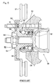
- a conventional wheel support bearing assembly designed to support the vehicle drive wheel such as shown in Fig. 5 includes, as major components, an inner member 50 made up of an hub unit 51 and an inner ring 52, double row rolling elements 53 and 54, an outer member 55 and a constant velocity universal joint 56 for transmitting an engine power to the hub unit 51.
- a wheel support bearing assembly of a type, in which the attempts were made to, without altering the shape and the dimensions of the wheel mounting flange 58, reduce the weight and increase the strength of the hub unit 51.
- This wheel support bearing assembly is illustrated in Fig. 4 and includes a surface hardened layer 62 formed by means of an induction hardening technique in the corner area 61 of the wheel mounting flange 58 in the hub unit 51.
- the corner area 61 of the wheel mounting flange 58 which has hitherto been considered the most fragile area susceptible to the rotational bending fatigue, can be reinforced to a high strength, resulting in increase of the durability of the hub unit 51.
- a seal land area a where a sealing lip (not shown) of the seal mounted on an outboard end portion of the outer member 55 ( Fig. 5 ), and various parts b to d extending from rolling surfaces to the radially inwardly stepped area are formed with a surface hardened layer 63 by means of an induction hardening technique or the like.
- the serrations 64 formed on the inner peripheral surface of the hub unit 51 are formed with a surface hardened layer 65. Thanks to those surface hardened layers 63 and 65, the rolling fatigue lifetime, the frictional wear resistance and the rotational bending fatigue strength required in those parts a to d can be increased.
- Patent Document 1 Japanese Laid-open Patent Publication No. 2002-087008 (Pages 4 and 5 and Fig. 2 thereof.)
- Patent Document 2 Japanese Laid-open Patent Publication No. 2005-003061
- the surface runout referred to above in turn results in brake judder under the influence of wobbling of the brake rotor 57 ( Fig. 5 ), thus leading to reduction in automobile drivability and driving feeling. Therefore, it may be contemplated to eliminate the surface runout by additionally performing a machining process on the brake rotor mounting surface 59 after the heat treatment of the hub unit 51 to compensate for the deformation.
- the presence of a difference in hardness between the corner area 61, which has been hardened, and the brake rotor mounting surface 59, which has not been hardened involves such a problem that a slight step tends to be formed at the boundary between the brake rotor mounting surface 59 and the surface hardened layer 62 of the corner area 61.
- the applicant or assignee of the present invention has suggested such a method (the Patent Document 2 listed above) that in a wheel support bearing assembly of the type, in which the wheel mounting flange is formed integrally with one of the outer member and the inner member, at least one of the outer and inner members, which has the wheel mounting flange formed therein, is thermally refined.
- this technique requires method steps to heat-treat the outer member or the inner member after having been forged for thermal refinement, to a temperature equal to or lower than the A1 transformation temperature, then to quench it and finally to temper it to a temperature equal to or higher than 400°C.
- the present invention has been devised to substantially eliminate the various problems and inconveniences inherent in the conventional art and is intended to provide a method of manufacturing a wheel support bearing assembly, in which the strength and the durability of the hub unit under rotational bending conditions are increased and, at the same time, the weight thereof is reduced without altering the shape and dimension of the wheel mounting flange or without deteriorating the surface runout, to therefore obtaining the hardness and the strength both comparable with those of the conventionally thermal refined products.
- a method for manufacturing a . wheel support bearing assembly of the present invention discloses the features of claim 1.
- At least one of the outer and inner members which is formed with the wheel mounting flange referred to above, is forged and rendered to have a hardened troostite structure, a hardened sorbite structure or a mixed structure of hardened troostite and sorbite structures, so that respective rolling surfaces in the outer and inner members can have a predetermined surface hardness comparable with that obtained by means of a thermal refinement which includes quenching and tempering, by controlling the cooling rate in the forging or by causing it to undergo an isothermal transformation, such that the rolling surfaces on the outer and inner members are hardened to predetermined hardness.
- a desired bearing lifetime can be secured, and also the strength and the durability can be increased against the rotational bending fatigue without altering the shape and the dimension of the wheel mounting flange while keeping the existing processing method and existing equipments and facilities.
- the hardened sorbite structure is rather preferable. Selection of the hardened sorbite structure is effective to increase the ductility and the toughness and, therefore, the strength and the durability against the rotational bending fatigue can be increased further.
- the inner member may include the hub unit formed with the wheel mounting flange and an inner ring press-fitted onto the hub unit.
- the inner rolling surface opposed to one of the outer rolling surfaces formed in the outer member is formed directly in an outer peripheral surface of the hub unit.
- the inner rolling surface opposed to the other of the outer rolling surfaces is formed in an outer peripheral surface of the inner ring.
- the wheel support bearing assembly can have a reduced size and a reduced weight, and the strength and the durability of the hub unit can also be further increased as compared with those of the conventional counterpart.
- an outboard root portion of the wheel mounting flange preferably has a surface hardness set to a value within the range of 23 HRC to 35 HRC.
- the processability such as cutting can be increased, and the deformation during the heat treatment can also be suppressed, thereby avoiding deterioration of the surface runout precision of the brake rotor mounting surface of the wheel mounting flange resulting from the deformation during the heat treatment.
- the surface hardness of the bolt holes, into which the hub bolts are press fitted approach the surface hardness of the hub bolts so that some or all of the serrations of the hub bolts will be crushed enough to lower the fixing strength.
- an inboard end of the hub unit may be plastically deformed in a direction radially outwardly thereof to form a crimped portion and the inner ring is axially fixed by this crimped portion relative to the hub unit.
- the crimped portion is preferably tempered to have a surface hardness within the range of 18 HRC to 25 HRC.
- variation in hardness of the crimped portion can be suppressed and, without lowering the processability, the possibility of occurrence of fine cracks in the surface due to the plastic processing can be eliminated, resulting in further increase of the reliability in quality.
- outboard and inboard sealing elements are preferably disposed at opposed ends of the outer member, respectively, and a seal land area, with which a sealing lip of the outboard sealing element is slidingly engaged, is formed in an inboard root portion of the wheel mounting flange, the seal land area having a surface hardness set to a value within the range of 54 HRC to 64 HRC.
- the frictional wear resistance can be increased, and also the mechanical strength can be sufficiently increased against the rotational bending load on the wheel mounting flange and the strength and the durability of the hub unit can also be increased.
- the inner member or the outer member subject to the cooling rate controlling in forging or to the isothermal transformation is preferably made of a medium carbon steel containing carbon in a quantity within the range of 0.40 wt% to 0.80 wt%.
- this is particularly advantageous in terms of the easiness of forging, cutting performance, thermal refinement characteristic or economical efficiency and, also, this is particularly suitable in an induction hardening or the like.
- the wheel support bearing assembly referred to above is of a type used for the support of a vehicle drive wheel and is so designed and includes a hub unit 1, a double row rolling bearing unit 2 unitized together with the hub unit 1 into a unitary structure and a constant velocity universal joint 4 having an outer coupling member 40 mounted on an inner periphery of the hub unit 1 by means of serrations for torque transmission.
- the wheel support bearing assembly includes an outer member 5 having an inner periphery formed with double row outer rolling surfaces 5a and 5a and also having an outer periphery formed integrally with a vehicle body fitting flange 5b adapted to be secured to a vehicle body (not shown).
- the bearing assembly also includes the hub unit 1 having an outer periphery formed with one of inner rolling surfaces opposed to the respective outer rolling surfaces 5a and 5a, that is, an inner rolling surface la, an inner ring 6 press fitted onto a radially inwardly stepped area 1b of the hub unit 1 and having its outer periphery formed with the other of the inner rolling surfaces, that is, an inner rolling surface 6a, and a plurality of rows of rolling elements 7 and 7 accommodated between the outer rolling surfaces 5a and 5a and the inner rolling surfaces 1a and 6a.
- the double row rolling elements 7 and 7 are rollingly retained by respective retainers (not shown).
- the hub unit 1 and the inner ring 6 cooperate with each other to define an inner member 3.
- sealing elements 8 and 8 are mounted in opposed ends of the double row rolling bearing unit 2 to avoid leakage of a lubricant grease, filled inside the interior of the bearing unit, and also to avoid ingress of rain water and/or dust from the outside.
- a seal land area 22, with which a sealing lip of the outboard sealing element 8 is slidingly engaged, is formed in an inboard root portion of the wheel mounting flange 10.
- the hub unit 1 has an insertion hole 42 defined in a center portion thereof and also has an inner periphery formed with torque transmitting serrations (or spline grooves or projections) 9 and is formed integrally with a wheel mounting flange 10 on an outer periphery of an outboard end thereof for supporting a vehicle wheel WH together with a brake rotor 24 for rotation together therewith. Also, a plurality of hub bolts 11 for fixedly retaining the vehicle wheel are secured to the wheel mounting flange 10 in a fashion spaced equidistantly from each other in a direction circumferentially of the flange 10.
- the constant velocity universal joint 4 includes, in addition to the outer coupling member 40 referred to hereinabove, an inner coupling member (not shown), torque transmitting balls accommodated between the inner coupling member and the outer coupling member 40, and a ball cage for retaining the torque transmitting balls in a fashion spaced equidistantly from each other in a circumferential direction thereof.
- the outer coupling member 40 includes a cup-shaped mouth portion 13, a shoulder portion 14 defining a bottom of the mouth portion 13 and a stem portion 15 extending axially from the shoulder portion 14.
- the stem portion 15 has an outer peripheral surface formed with complemental serrations (or splines) 16 and also has a free end portion formed with a male thread 17.
- the hub unit 1 is, after a medium carbon steel such as, for example, S53C containing carbon in a quantity within the range of 0.40 wt% to 0.80 wt% as stipulated in the Japanese Industrial Standards (or JIS for short) has been hot forged, rendered to have a troostite structure, a sorbite structure or a mixed structure of troostite and sorbite by force-air-cooling or thermostatically maintaining the hub unit 1 within a predetermined temperature range, thereby controlling the cooling rate, so that the hub unit 1 can have a hardness within the range of HRC 23 and HRC 35, followed by turned to have a desired shape and dimension.
- a medium carbon steel such as, for example, S53C containing carbon in a quantity within the range of 0.40 wt% to 0.80 wt% as stipulated in the Japanese Industrial Standards (or JIS for short) has been hot forged, rendered to have a troostite structure, a sorbite structure or a mixed structure of troostite
- An area of the root portion of the wheel mounting flange 10 on the outboard side, that is the corner area 21 ranging from an outboard end surface of the wheel mounting flange 10, that is, a brake rotor mounting surface 19 to a cylindrical pilot portion 20 defining a support face for the brake rotor 24 is formed to represent an arcuate surface or recess portion having a radius of curvature enough to avoid interference with the brake rotor 24.
- the hub unit 1 has a hardness within the range of 23 HRC to 35 HRC as a result that the hub unit 1 has been cooled in a controlled fashion so as to have the troostite structure, the sorbite structure or the mixed structure of troostite and sorbite after having been forged.
- the structure is refined so as to be approximately equivalent to the conventional ferrite-pearlite structure, resulting in improvement of mechanical characteristics such as tensile strength, bending strength or impact value, which in turn result in increase of the ductility and the toughness.
- the hub unit 1 can have a high strength comparable with the conventional counterparts that are thermally refined (quenched and tempered at elevated temperature).
- thermal refinement may be performed. It is, however, to be noted that this process is not necessarily limited to the thermal refinement.
- the hub unit 1 has its surface hardness set to be within the range of a value equal to or lower than 35 HRC.
- the surface hardness is because if the surface hardness is set to be higher than 35 HRC, the processability such as, for example, machinability can be lowered, and also thermal deformation will take place considerably, and, therefore, the surface runout precision of the brake rotor mounting surface 19 of the wheel mounting flange 10 will be deteriorated and, also, service lives of a cutting tool will be reduced consequently upon increase of the surface hardness. Also, the surface hardness of bolt holes 11a for receiving the hub bolts 11 press-fitted thereto comes close to the surface hardness of the hub bolts 11 so that some or all of the serrations 11b of the hub bolts 11 will be crushed enough to lower the fixing strength.
- the surface hardness of the hub unit 1 is set to a value equal to or lower than 35 HRC and to improve the processability such as, for example, a cutting performance during the subsequent method step.
- the following advantages can also be obtained: It is possible to suppress the thermal deformation, which would otherwise occur during the heat treatment, to thereby avoid deterioration of the surface runout precision of the brake rotor mounting surface 19 on the wheel mounting flange 10. Moreover, it is possible to avoid reduction in machinability, which would result from the increase of the surface hardness, accompanied by extension of the service life of the cutting tool, compared to the case having a surface hardness higher than 35 HRC.
- the surface hardness of the bolt holes 11 a for receiving the respective press-fit hub bolts 11 and the surface hardness of the hub bolts 11 can be differentiated from each other such that crush of the serrations 11b of the hub bolts 11 can be prevented beforehand, thereby suppressing reduction in fixing strength of the hub bolts 11.
- the surface hardness of the inboard end portion of the hub unit 1 exceeds the upper limit of 35 HRC, not only will the processability be lowered, but also there is a risk that due to plastic forming, fine cracks will occur in the surface, accompanied by reduction in reliability of the quality.
- the surface hardness should be rather low, sufficient mechanical strength is difficult to obtain if it is lower than the lower limit of 18 HRC.
- the reliability will increase provided that in the crimped portion 12 the surface hardness thereof is chosen to be within the range of 18 HRC to 35 HRC and preferably within the range of 18 HRC to 25 HRC.
- the surface hardness of the hub unit may be set to a value equal to or lower than 35 HRC without performing a thermal refinement on the hub unit by hot-forging the material for the hub unit, that is, a medium carbon steel and then by forced-air-cooling or thermostatically maintaining it within a predetermined temperature range, thereby controlling the cooling rate. Even in this case, advantages similar to those afforded by the foregoing embodiment of the present invention can be obtained.
- the cooling rate for the forged hub unit 1 controls the cooling rate for the forged hub unit 1 to provide a desired microstructure, that is, the troostite structure, the sorbite structure or a mixed structure of troostite and sorbite and also to set the surface hardness within the predetermined range as discussed above, without altering the shape and dimension of the wheel mounting flange 10, the strength of the corner area 21, which forms the most fragile portion susceptible to rotational bending fatigue, can be increased while keeping the existing processing method and existing equipments.
- the surface runout precision of the brake rotor mounting surface 19 of the wheel mounting flange 10 can be further improved as compared with that in the conventional counterpart.
- occurrence of cracking can be suppressed without the processability during the plastic forming being reduced, thus allowing the reliability in quality to be maintained.
- Table 1 illustrates the 10 7 times fatigue strength ratios by the conventional ferrite-pearlite structure in the S53C material, the two thermally refined structure (oil quenching after heating at 850°C, followed by tempering at 400°C and 600°C) and two structures produced according to the present invention, all of these structures having been derived from model rings, that is, test pieces.
- the structures produced according to the present invention refer to the test piece, which was cooled down to 400°C at a rate of 200°C per minute after having been forged, and to the test piece which was rapidly cooled after having been retained at 550°C for 5 minutes subsequent to the forging.
- Test conditions employed are shown in Table 2.
- each of the test pieces was a model ring of 38 mm in outer diameter, 30 mm in inner diameter and 15 mm in width.
- Table 1 Conditions Representative Microstructures Ratios of Fatigue Strengths As forged Ferrite-pearlite 0.6 Thermally refined (400°C) Tempered troostite 1.1 Thermally refined (600°C) Tempered sorbite 1.0 Cooled down to 400°C at a rate of 200°C/min.
- the thermally refined test piece having the thermally refined structure which was, after having been heated at 850°C, oil quenched and tempered at 600°C has exhibited the fatigue strength ratio of 1.0
- the thermally refined test piece having the thermally refined structure which was, after having been heated at 850°C, oil quenched and tempered at 400°C has exhibited the fatigue strength ratio of 1.1.
- test pieces, processed according to the present invention which was cooled down to 400°C at a rate of 200°C per minute subsequent to the forging, has shown the fatigue strength ratio of 0.9 and the test piece, processed according to the present invention, which was rapidly cooled after having been retained at 550°C for 5 minutes subsequent to the forging, has shown the fatigue strength ratio of 1.0.
- the present invention can provide the fatigue strengths comparable remarkably with those exhibited by the thermally refined products.
- the hub unit 1 is such that the inner rolling surface la on the outboard side, the seal land area 22 where the sealing element 8 undergoes a sliding contact, and the radially inwardly stepped area 1b are formed, respectively, with a hardened layer 23 (shown by cross hatchings in the drawing) of a surface hardness within the range of 54 HRC to 64 HRC by means of an induction hardening process. Accordingly, the seal land area 22 can have an increased frictional wear resistance and also a sufficient mechanical strength against the rotational bending load on the wheel mounting flange 10, with the durability of the hub unit 1 being increased consequently.
- the inner ring 6 that is press-fitted onto the radially inwardly stepped area 1b is made of a high-carbon chromium bearing steel such as, for example, SUJ2 stipulated according to the JIS and is hardened deep down to the core by means of a dip quenching technique to have a hardness within the range of 58 HRC to 64 HRC.
- the outer member 5 is made of a medium carbon steel such as, for example, S53C containing carbon within the range of 0.40 wt% to 80 wt% as is the case with the hub unit 1 and the double row outer rolling surfaces 5a and 5a and the end inner diametric surface, in which the sealing elements 8 and 8 are engaged, are hardened by means of an induction hardening process to have a surface hardness within the range of 54 HRC to 64 HRC.
- a medium carbon steel such as, for example, S53C containing carbon within the range of 0.40 wt% to 80 wt% as is the case with the hub unit 1 and the double row outer rolling surfaces 5a and 5a and the end inner diametric surface, in which the sealing elements 8 and 8 are engaged, are hardened by means of an induction hardening process to have a surface hardness within the range of 54 HRC to 64 HRC.
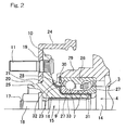
- Fig. 2 illustrates a sectional view of the wheel support bearing assembly according to a second preferred embodiment of the present invention. This second embodiment is applied to the wheel support bearing assembly of the first generation type.
- component parts similar to those shown and described in connection with the previously described embodiment including modifications thereof arc designated by like reference numerals and the details thereof will not be reiterated for the sake of brevity.
- This wheel support bearing assembly includes a hub unit 25, to which a vehicle wheel (not shown) is fitted together with a brake rotor 24, and a wheel support bearing unit 28 for rotatably supporting the hub unit 25 and having an outer ring 26, a pair of inner rings 27 and 27 arranged in an axial direction, and double row rolling elements 7 and 7 rollingly accommodated between the inner and outer rings 27 and 26.
- This bearing unit 28 is fitted to a knuckle 29 of the automotive vehicle and is drivingly coupled with a constant velocity universal joint 4 for transmitting the drive of a drive shaft (not shown) to the hub unit 25.
- a double row angular contact bearing employing balls for the rolling elements 7 and 7 has been shown, the present invention is not necessarily limited thereto and can be applied to a double row tapered roller bearing utilizing tapered rollers for the rolling elements.
- the outer ring 26 of the wheel support bearing unit 28 is mounted inside the knuckle 29 and axially fixedly positioned by means of a stop ring 30.
- the pair of the inner rings 27 and 27 are press-fitted onto a radially inwardly stepped area 31 of a cylindrical configuration formed in the hub unit 25 and the constant velocity universal joint 4 is separably coupled with the hub unit 25 when while a large diameter side end face of the inner ring 27 on the inboard side is brought into abutment with a shoulder 14 of the outer coupling member 40 a free end of the stem portion 15 is fastened by an anchoring nut 18.
- the hub unit 25 is, after a medium carbon steel such as, for example, S53C, containing carbon in a quantity within the range of 0.40 wt% to 0.80 wt%, has been hot forged, cooled in a controlled manner, with the surface hardness consequently set to a value within the range of 23 HRC to 35 HRC.
- a medium carbon steel such as, for example, S53C, containing carbon in a quantity within the range of 0.40 wt% to 0.80 wt%
- the surface hardness of the hub unit 25 may be set to a value equal to or lower than 35 HRC without performing a thermal refinement on the hub unit 25 by hot-forging the material for the hub unit 25, that is, a medium carbon steel and then by forced-air-cooling or thermostatically maintaining it within a predetermined temperature range, thereby controlling the cooling rate. Even in this case, advantages similar to those afforded by the foregoing embodiment of the present invention can be obtained.
- an inboard root portion 32 of the wheel mounting flange 10 in the hub unit 25 is so designed that as is the case with the inboard root portion 22 shown and described in connection with the first embodiment of the present invention, the radius of curvature thereof is set to a value as large as possible and a region ranging from this root portion 32 to the radially inwardly stepped area 31 is hardened by an induction hardening technique to obtain a hardened layer 23 (shown by the cross hatched area in the drawing) having a surface hardness within the range of 54 HRC to 64 HRC. Thanks to this construction, a sufficient mechanical strength is provided against the rotational bending load on the wheel mounting flange 10 and the durability of the hub unit 25 can be increased consequently.
- the pair of the inner rings 27 and 27 that are press-fitted onto the radially inwardly stepped area 31 are made of a high carbon and chromium bearing steel such as, for example, SUJ2 and are hardened deep down to the core by means of a dip quenching technique to have a hardness within the range of 58 HRC to 64 HRC.
- the fretting abrasion which would occur between the radially inwardly stepped area 31 and the inner races 27 and 27, is suppressed effectively.
- surfaces of the serrations 9 formed on the inner peripheral surface of the hub unit 25 are formed with hardened layers 33 (shown by the cross hatched area in the drawing) of a surface hardness within the range of 54 HRC to 64 HRC achieved by means of an induction hardening.
- the frictional wear resistance of the serrations 9 can increase, and also the effective length of the serrations 9 can be reduced as a result of the increased strength, thus contributing to reduction in size and weight of the hub axle 25.
- the outer ring 26 is, as is the case with the inner ring 27, made of a high carbon chromium bearing steel such as, for example, SUJ2 and is hardened deep down to the core by means of the dip quenching technique to have a hardness within the range of 54 HRC to 64 HRC.
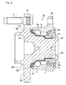
- Fig. 3 illustrates a sectional view of the wheel support bearing assembly according to a third preferred embodiment of the present invention.
- This third embodiment is applied to the wheel support bearing assembly of the so-called third generation type, and component parts, portions or functions employed therein, but similar to those shown and described in connection with the previously described first and second embodiments are designated by like reference numerals and, therefore, the details thereof will not be reiterated for the sake of brevity.
- This wheel support bearing assembly is for supporting a vehicle driven wheel and includes the hub unit 34 and a double row rolling bearing unit 35 unitized together with thee hub unit 34.
- the double row rolling bearing unit 35 includes an outer member 5, a hub unit 34, a separate inner ring 6 press-fitted onto the radially inwardly stepped area 1b defmed in the hub axle 34, and double row rolling elements 7 and 7.
- the hub unit 34 has a surface hardness set to be within the range of 23 HRC to 35 HRC by performing thereon a controlled cooling process after the medium carbon steel containing carbon within the range of 0.40 wt% to 0.80 wt%, such as, for example, S53C or the like, has been hot forged.
- a controlled cooling process after the hub unit 34 has been forged in this manner to have the desired surface hardness, the strength of the corner area 21, which is the most fragile area susceptible to the rotational bending fatigue, can be increased with no need to alter the shape and the dimension of the wheel mounting flange 10.
- an inboard root portion of the wheel mounting flange 10 in the hub unit 32 defines the seal land area 22 for the inboard sealing element 8, which area 22 has a radius of curvature so as to be as large as possible.
- a region ranging from this seal land area 22 to the radially inwardly stepped area 1b is hardened by an induction hardening technique to obtain a hardened layer 23 (shown by the cross hatched area in the drawing) having a surface hardness within the range of 54 HRC to 64 HRC.
- the seal land area 22 can have an increased frictional wear resistance, and also a sufficient mechanical strength is exhibited against the rotational bending load acting on the wheel mounting flange 10 and the durability of the hub unit 34 can be increased consequently.
- the controlled cooling process is performed to render the hub unit 34 to have a surface hardness within the range of 23 HRC to 35 HRC, the strength of the corner area 21, which is the most fragile area susceptible to the rotational bending fatigue, can be increased with no need to alter the shape and the dimension of the wheel mounting flange 10.
- Other structural features are similar to those afforded by the embodiment shown in and described with particular reference to Fig. 1 .
- the present invention may not necessarily be limited thereto and may be applied to a wheel support bearing assembly of an outer rotating type, in which the outer member is formed integrally with the wheel mounting flange. In this case, the thermal refinement will be performed on the outer member.
Landscapes
- Engineering & Computer Science (AREA)
- Mechanical Engineering (AREA)
- General Engineering & Computer Science (AREA)
- Manufacturing & Machinery (AREA)
- Rolling Contact Bearings (AREA)
- Mounting Of Bearings Or Others (AREA)
- Sealing Of Bearings (AREA)
- Forging (AREA)
- Braking Arrangements (AREA)
- Turbine Rotor Nozzle Sealing (AREA)
Claims (8)
- Verfahren zur Herstellung einer Radstützlageranordnung, die folgendes umfasst:ein äußeres Element (5), das einen inneren Umfang aufweist, der mit zweireihigen Wälzflächen (5a) ausgebildet ist,ein inneres Element (3), das mit zweireihigen Wälzflächen (1a, 6a) ausgebildet ist, die den entsprechenden Reihen von Wälzflächen (5a) an dem äußeren Element (5) gegenüberliegen,zweireihige Wälzelemente (7), die wälzbar zwischen den jeweiligen Wälzflächen (5a; 1a, 6a) des äußeren und inneren Elements (5, 3) aufgenommen sind, undeinen Radbefestigungsflansch, der integral mit dem äußeren oder dem inneren Element (5, 3) ausgebildet ist,dadurch gekennzeichnet,dass wenigsten eines des äußeren und des inneren Elements (5, 3), das mit dem Radbefestigungsflansch (10) ausgebildet ist, geschmiedet und derart ausgeführt ist, durch Steuern einer Kühlrate im Schmiedeprozess eine Troostitstruktur, eine Sorbitstruktur oder eine Mischstruktur aus Troostit und Sorbit aufzuweisen, so dass die Wälzflächen (5a; 1a, 6a) an dem äußeren und inneren Element (5, 3) zu einer vorbestimmten Oberflächenhärte gehärtet werden.
- Verfahren nach Anspruch 1, wobei das innere Element (3) die Nabeneinheit (1, 25, 34) enthält, die mit dem Radbefestigungsflansch (10) und einem inneren Ring (6), welcher auf die Nabeneinheit (1, 25, 34) aufgepresst ist, ausgebildet ist; die innere Wälzfläche (1a), welche einer der äußeren Wälzflächen (5a), die in dem äußeren Element (5) gebildet ist, gegenüberliegt, direkt in einer äußeren Umfangsfläche der Nabeneinheit (1, 25, 34) gebildet ist; und die innere Wälzfläche (6a), welche den anderen äußeren Wälzflächen (5a) gegenüberliegt, in einer äußeren Umfangsfläche des inneren Rings (6) gebildet ist.
- Verfahren nach Anspruch 1, wobei ein äußerer Hauptabschnitt des Radbefestigungsflansches (10) eine Oberflächenhärte aufweist, die auf einen Wert innerhalb des Bereichs von 23 HRC bis 35 HRC gesetzt ist.
- Verfahren nach Anspruch 2, wobei ein inneres Ende der Nabeneinheit (1, 34) in einer radial nach außen laufenden Richtung plastisch deformiert ist, um einen gebördelten Abschnitt (12) zu bilden, und der innere Ring (6) durch diesen gebördelten Abschnitt (12) im Verhältnis zur Nabeneinheit (1, 34) axial fixiert ist.
- Verfahren nach Anspruch 4, wobei der gebördelte Abschnitt (12) getempert ist, um eine Oberflächenhärte innerhalb des Bereichs von 18 HRC bis 25 HRC aufzuweisen.
- Verfahren nach Anspruch 2, wobei äußere und innere Dichtungselemente (8) jeweils an gegenüberliegenden Enden des äußeren Elements (5) angeordnet sind und eine Dichtungsanquetschfläche (22), mit welcher eine Dichtlippe des äußeren Dichtelements (8) gleitend in Eingriff steht, in einem inneren Hauptabschnitt (32) des Radbefestigungsflansches (10) gebildet ist, wobei die Dichtungsanquetschfläche (22) eine Oberflächenhärte aufweist, die auf einen Wert innerhalb des Bereichs von 54 HRC bis 64 HRC gesetzt ist.
- Verfahren nach Anspruch 1, wobei das innere Element (3) oder das äußere Element (5), welches der beim Schmieden gesteuerten Kühlrate oder der isothermischen Umformung unterzogen ist, aus einem kohlenstoffmittelreichen Stahl hergestellt ist, der Kohlenstoff in einer Menge innerhalb des Bereichs von 0,40 Gew.% bis 0,80 Gew.% enthält.
- Verfahren nach Anspruch 1, umfassend die folgenden Schritte:Schmieden des äußeren Elements (5) oder des inneren Elements (3);Kühlen desselben bei einer Kühlrate innerhalb des Bereichs von 100 °C bis 300 °C pro Minute bei einer Temperatur innerhalb des Bereichs von 400 °C bis 700 °C; undVerwenden einer gesteuerten Kühlung, um ferner luftzukühlen, um so ein Troostitstruktur, eine Sorbitstruktur oder eine Mischstruktur aus Troostit und Sorbit zu bilden, wodurch eine vorgegebene Struktur und eine vorgegebene Härte erhalten wird.
Applications Claiming Priority (2)
| Application Number | Priority Date | Filing Date | Title |
|---|---|---|---|
| JP2007043595A JP2008207586A (ja) | 2007-02-23 | 2007-02-23 | 車輪用軸受装置およびその製造方法 |
| PCT/JP2008/000231 WO2008102529A1 (ja) | 2007-02-23 | 2008-02-15 | 車輪用軸受装置およびその製造方法 |
Publications (3)
| Publication Number | Publication Date |
|---|---|
| EP2113394A1 EP2113394A1 (de) | 2009-11-04 |
| EP2113394A4 EP2113394A4 (de) | 2010-03-10 |
| EP2113394B1 true EP2113394B1 (de) | 2011-11-09 |
Family
ID=39709810
Family Applications (1)
| Application Number | Title | Priority Date | Filing Date |
|---|---|---|---|
| EP08710385A Not-in-force EP2113394B1 (de) | 2007-02-23 | 2008-02-15 | Lager für rad und herstellungsverfahren dafür |
Country Status (4)
| Country | Link |
|---|---|
| EP (1) | EP2113394B1 (de) |
| JP (1) | JP2008207586A (de) |
| AT (1) | ATE532646T1 (de) |
| WO (1) | WO2008102529A1 (de) |
Cited By (1)
| Publication number | Priority date | Publication date | Assignee | Title |
|---|---|---|---|---|
| CN111278662A (zh) * | 2017-10-24 | 2020-06-12 | Ntn株式会社 | 车轮用轴承装置及其制造方法 |
Families Citing this family (2)
| Publication number | Priority date | Publication date | Assignee | Title |
|---|---|---|---|---|
| CN106525591B (zh) * | 2016-11-30 | 2023-09-12 | 西南交通大学 | 基于旋转弯曲疲劳的材料损伤容限检测装置及检测方法 |
| US12247621B2 (en) | 2017-10-24 | 2025-03-11 | Ntn Corporation | Wheel bearing device |
Family Cites Families (11)
| Publication number | Priority date | Publication date | Assignee | Title |
|---|---|---|---|---|
| JP3954772B2 (ja) * | 2000-04-26 | 2007-08-08 | 新日本製鐵株式会社 | 結晶粒粗大化防止特性に優れた高温浸炭部品用素形材とその製造方法 |
| JP3989168B2 (ja) | 2000-09-20 | 2007-10-10 | Ntn株式会社 | 車輪軸受装置 |
| JP2004156764A (ja) * | 2002-08-29 | 2004-06-03 | Nsk Ltd | フランジ付軸受装置及び該装置の製造方法 |
| JP4063722B2 (ja) * | 2003-06-11 | 2008-03-19 | Ntn株式会社 | 車輪用軸受装置 |
| JP2005188599A (ja) * | 2003-12-25 | 2005-07-14 | Ntn Corp | 車輪用軸受装置 |
| JP2006226373A (ja) * | 2005-02-16 | 2006-08-31 | Nsk Ltd | 車輪支持用転がり軸受ユニット |
| JP4013969B2 (ja) * | 2005-06-29 | 2007-11-28 | Jfeスチール株式会社 | 疲労強度に優れた熱間鍛造品およびその製造方法並びに機械構造部品 |
| US8240922B2 (en) * | 2005-07-20 | 2012-08-14 | Ntn Corporation | Bearing device for wheel |
| JP2007024273A (ja) * | 2005-07-20 | 2007-02-01 | Ntn Corp | 車輪用軸受装置の製造方法 |
| JP5019727B2 (ja) * | 2005-07-20 | 2012-09-05 | Ntn株式会社 | 車輪用軸受装置 |
| JP2007043595A (ja) | 2005-08-05 | 2007-02-15 | Nec Corp | 可変長符号復号化方法および装置ならびにデータ伸長装置 |
-
2007
- 2007-02-23 JP JP2007043595A patent/JP2008207586A/ja active Pending
-
2008
- 2008-02-15 WO PCT/JP2008/000231 patent/WO2008102529A1/ja not_active Ceased
- 2008-02-15 AT AT08710385T patent/ATE532646T1/de active
- 2008-02-15 EP EP08710385A patent/EP2113394B1/de not_active Not-in-force
Cited By (3)
| Publication number | Priority date | Publication date | Assignee | Title |
|---|---|---|---|---|
| CN111278662A (zh) * | 2017-10-24 | 2020-06-12 | Ntn株式会社 | 车轮用轴承装置及其制造方法 |
| US11506241B2 (en) * | 2017-10-24 | 2022-11-22 | Ntn Corporation | Wheel bearing device and method for manufacturing said device |
| CN111278662B (zh) * | 2017-10-24 | 2024-03-15 | Ntn株式会社 | 车轮用轴承装置及其制造方法 |
Also Published As
| Publication number | Publication date |
|---|---|
| EP2113394A4 (de) | 2010-03-10 |
| ATE532646T1 (de) | 2011-11-15 |
| JP2008207586A (ja) | 2008-09-11 |
| WO2008102529A1 (ja) | 2008-08-28 |
| EP2113394A1 (de) | 2009-11-04 |
Similar Documents
| Publication | Publication Date | Title |
|---|---|---|
| US7452136B2 (en) | Bearing apparatus for a wheel of vehicle | |
| US8192088B2 (en) | Wheel support bearing assembly and method of making the same | |
| US7695195B2 (en) | Bearing apparatus for a wheel of vehicle | |
| US7891879B2 (en) | Hub wheel of a wheel bearing apparatus and a manufacturing method thereof | |
| US9889493B2 (en) | Wheel bearing device with a clearance formed between the inner race and the hub wheel | |
| US20170043617A1 (en) | Drive wheel bearing and method of manufacturing the same | |
| US20100239202A1 (en) | Double-row angular bearing, bearing device for wheel, method of producing outer race, and method of producing inner race | |
| US8302309B2 (en) | Process for producing bearing device for wheel | |
| JP5121246B2 (ja) | 車輪用軸受装置およびその製造方法 | |
| JP2002021858A (ja) | 車輪軸受装置 | |
| US20090028485A1 (en) | Bearing Apparatus for a Wheel of Vehicle | |
| JP2001180210A (ja) | 車輪軸受装置 | |
| US7025685B2 (en) | Constant velocity universal joint and wheel bearing device using the same | |
| EP2113394B1 (de) | Lager für rad und herstellungsverfahren dafür | |
| JP4536086B2 (ja) | 車輪用軸受装置及びその製造方法 | |
| US7909517B2 (en) | Wheel support bearing assembly and manufacturing method thereof | |
| EP1925837A1 (de) | Homokinetisches kardangelenk | |
| JP5019727B2 (ja) | 車輪用軸受装置 | |
| JP5105727B2 (ja) | 車輪用軸受装置 | |
| JP2008296621A (ja) | 車輪用軸受装置 | |
| JP5105723B2 (ja) | 車輪用軸受装置 | |
| JP5121247B2 (ja) | 車輪用軸受装置 | |
| JP4471283B2 (ja) | 車輪用軸受装置 | |
| JP2001294005A (ja) | 車輪軸受装置 | |
| JP2007315545A (ja) | 駆動車輪用軸受装置の製造方法 |
Legal Events
| Date | Code | Title | Description |
|---|---|---|---|
| PUAI | Public reference made under article 153(3) epc to a published international application that has entered the european phase |
Free format text: ORIGINAL CODE: 0009012 |
|
| 17P | Request for examination filed |
Effective date: 20090827 |
|
| AK | Designated contracting states |
Kind code of ref document: A1 Designated state(s): AT BE BG CH CY CZ DE DK EE ES FI FR GB GR HR HU IE IS IT LI LT LU LV MC MT NL NO PL PT RO SE SI SK TR |
|
| A4 | Supplementary search report drawn up and despatched |
Effective date: 20100208 |
|
| DAX | Request for extension of the european patent (deleted) | ||
| 17Q | First examination report despatched |
Effective date: 20100802 |
|
| GRAP | Despatch of communication of intention to grant a patent |
Free format text: ORIGINAL CODE: EPIDOSNIGR1 |
|
| RIN1 | Information on inventor provided before grant (corrected) |
Inventor name: OHTSUKI, HISASHIC/O NTN CORPORATION Inventor name: MAEDA, KIKUOC/O NTN CORPORATION |
|
| GRAS | Grant fee paid |
Free format text: ORIGINAL CODE: EPIDOSNIGR3 |
|
| GRAA | (expected) grant |
Free format text: ORIGINAL CODE: 0009210 |
|
| AK | Designated contracting states |
Kind code of ref document: B1 Designated state(s): AT BE BG CH CY CZ DE DK EE ES FI FR GB GR HR HU IE IS IT LI LT LU LV MC MT NL NO PL PT RO SE SI SK TR |
|
| REG | Reference to a national code |
Ref country code: GB Ref legal event code: FG4D |
|
| REG | Reference to a national code |
Ref country code: CH Ref legal event code: EP |
|
| REG | Reference to a national code |
Ref country code: IE Ref legal event code: FG4D |
|
| REG | Reference to a national code |
Ref country code: DE Ref legal event code: R096 Ref document number: 602008011255 Country of ref document: DE Effective date: 20120105 |
|
| REG | Reference to a national code |
Ref country code: NL Ref legal event code: VDEP Effective date: 20111109 |
|
| LTIE | Lt: invalidation of european patent or patent extension |
Effective date: 20111109 |
|
| PG25 | Lapsed in a contracting state [announced via postgrant information from national office to epo] |
Ref country code: NO Free format text: LAPSE BECAUSE OF FAILURE TO SUBMIT A TRANSLATION OF THE DESCRIPTION OR TO PAY THE FEE WITHIN THE PRESCRIBED TIME-LIMIT Effective date: 20120209 Ref country code: IS Free format text: LAPSE BECAUSE OF FAILURE TO SUBMIT A TRANSLATION OF THE DESCRIPTION OR TO PAY THE FEE WITHIN THE PRESCRIBED TIME-LIMIT Effective date: 20120309 Ref country code: LT Free format text: LAPSE BECAUSE OF FAILURE TO SUBMIT A TRANSLATION OF THE DESCRIPTION OR TO PAY THE FEE WITHIN THE PRESCRIBED TIME-LIMIT Effective date: 20111109 |
|
| PG25 | Lapsed in a contracting state [announced via postgrant information from national office to epo] |
Ref country code: LV Free format text: LAPSE BECAUSE OF FAILURE TO SUBMIT A TRANSLATION OF THE DESCRIPTION OR TO PAY THE FEE WITHIN THE PRESCRIBED TIME-LIMIT Effective date: 20111109 Ref country code: NL Free format text: LAPSE BECAUSE OF FAILURE TO SUBMIT A TRANSLATION OF THE DESCRIPTION OR TO PAY THE FEE WITHIN THE PRESCRIBED TIME-LIMIT Effective date: 20111109 Ref country code: GR Free format text: LAPSE BECAUSE OF FAILURE TO SUBMIT A TRANSLATION OF THE DESCRIPTION OR TO PAY THE FEE WITHIN THE PRESCRIBED TIME-LIMIT Effective date: 20120210 Ref country code: HR Free format text: LAPSE BECAUSE OF FAILURE TO SUBMIT A TRANSLATION OF THE DESCRIPTION OR TO PAY THE FEE WITHIN THE PRESCRIBED TIME-LIMIT Effective date: 20111109 Ref country code: BE Free format text: LAPSE BECAUSE OF FAILURE TO SUBMIT A TRANSLATION OF THE DESCRIPTION OR TO PAY THE FEE WITHIN THE PRESCRIBED TIME-LIMIT Effective date: 20111109 Ref country code: PL Free format text: LAPSE BECAUSE OF FAILURE TO SUBMIT A TRANSLATION OF THE DESCRIPTION OR TO PAY THE FEE WITHIN THE PRESCRIBED TIME-LIMIT Effective date: 20111109 Ref country code: PT Free format text: LAPSE BECAUSE OF FAILURE TO SUBMIT A TRANSLATION OF THE DESCRIPTION OR TO PAY THE FEE WITHIN THE PRESCRIBED TIME-LIMIT Effective date: 20120309 Ref country code: SI Free format text: LAPSE BECAUSE OF FAILURE TO SUBMIT A TRANSLATION OF THE DESCRIPTION OR TO PAY THE FEE WITHIN THE PRESCRIBED TIME-LIMIT Effective date: 20111109 Ref country code: SE Free format text: LAPSE BECAUSE OF FAILURE TO SUBMIT A TRANSLATION OF THE DESCRIPTION OR TO PAY THE FEE WITHIN THE PRESCRIBED TIME-LIMIT Effective date: 20111109 |
|
| PG25 | Lapsed in a contracting state [announced via postgrant information from national office to epo] |
Ref country code: CY Free format text: LAPSE BECAUSE OF FAILURE TO SUBMIT A TRANSLATION OF THE DESCRIPTION OR TO PAY THE FEE WITHIN THE PRESCRIBED TIME-LIMIT Effective date: 20111109 |
|
| PG25 | Lapsed in a contracting state [announced via postgrant information from national office to epo] |
Ref country code: DK Free format text: LAPSE BECAUSE OF FAILURE TO SUBMIT A TRANSLATION OF THE DESCRIPTION OR TO PAY THE FEE WITHIN THE PRESCRIBED TIME-LIMIT Effective date: 20111109 Ref country code: BG Free format text: LAPSE BECAUSE OF FAILURE TO SUBMIT A TRANSLATION OF THE DESCRIPTION OR TO PAY THE FEE WITHIN THE PRESCRIBED TIME-LIMIT Effective date: 20120209 Ref country code: EE Free format text: LAPSE BECAUSE OF FAILURE TO SUBMIT A TRANSLATION OF THE DESCRIPTION OR TO PAY THE FEE WITHIN THE PRESCRIBED TIME-LIMIT Effective date: 20111109 Ref country code: CZ Free format text: LAPSE BECAUSE OF FAILURE TO SUBMIT A TRANSLATION OF THE DESCRIPTION OR TO PAY THE FEE WITHIN THE PRESCRIBED TIME-LIMIT Effective date: 20111109 Ref country code: SK Free format text: LAPSE BECAUSE OF FAILURE TO SUBMIT A TRANSLATION OF THE DESCRIPTION OR TO PAY THE FEE WITHIN THE PRESCRIBED TIME-LIMIT Effective date: 20111109 |
|
| PG25 | Lapsed in a contracting state [announced via postgrant information from national office to epo] |
Ref country code: RO Free format text: LAPSE BECAUSE OF FAILURE TO SUBMIT A TRANSLATION OF THE DESCRIPTION OR TO PAY THE FEE WITHIN THE PRESCRIBED TIME-LIMIT Effective date: 20111109 Ref country code: IT Free format text: LAPSE BECAUSE OF FAILURE TO SUBMIT A TRANSLATION OF THE DESCRIPTION OR TO PAY THE FEE WITHIN THE PRESCRIBED TIME-LIMIT Effective date: 20111109 |
|
| PLBE | No opposition filed within time limit |
Free format text: ORIGINAL CODE: 0009261 |
|
| STAA | Information on the status of an ep patent application or granted ep patent |
Free format text: STATUS: NO OPPOSITION FILED WITHIN TIME LIMIT |
|
| REG | Reference to a national code |
Ref country code: AT Ref legal event code: MK05 Ref document number: 532646 Country of ref document: AT Kind code of ref document: T Effective date: 20111109 |
|
| PG25 | Lapsed in a contracting state [announced via postgrant information from national office to epo] |
Ref country code: MC Free format text: LAPSE BECAUSE OF NON-PAYMENT OF DUE FEES Effective date: 20120229 |
|
| REG | Reference to a national code |
Ref country code: CH Ref legal event code: PL |
|
| 26N | No opposition filed |
Effective date: 20120810 |
|
| GBPC | Gb: european patent ceased through non-payment of renewal fee |
Effective date: 20120215 |
|
| PG25 | Lapsed in a contracting state [announced via postgrant information from national office to epo] |
Ref country code: CH Free format text: LAPSE BECAUSE OF NON-PAYMENT OF DUE FEES Effective date: 20120229 Ref country code: LI Free format text: LAPSE BECAUSE OF NON-PAYMENT OF DUE FEES Effective date: 20120229 |
|
| REG | Reference to a national code |
Ref country code: IE Ref legal event code: MM4A |
|
| REG | Reference to a national code |
Ref country code: DE Ref legal event code: R097 Ref document number: 602008011255 Country of ref document: DE Effective date: 20120810 |
|
| PG25 | Lapsed in a contracting state [announced via postgrant information from national office to epo] |
Ref country code: GB Free format text: LAPSE BECAUSE OF NON-PAYMENT OF DUE FEES Effective date: 20120215 Ref country code: IE Free format text: LAPSE BECAUSE OF NON-PAYMENT OF DUE FEES Effective date: 20120215 Ref country code: AT Free format text: LAPSE BECAUSE OF FAILURE TO SUBMIT A TRANSLATION OF THE DESCRIPTION OR TO PAY THE FEE WITHIN THE PRESCRIBED TIME-LIMIT Effective date: 20111109 |
|
| PG25 | Lapsed in a contracting state [announced via postgrant information from national office to epo] |
Ref country code: ES Free format text: LAPSE BECAUSE OF FAILURE TO SUBMIT A TRANSLATION OF THE DESCRIPTION OR TO PAY THE FEE WITHIN THE PRESCRIBED TIME-LIMIT Effective date: 20120220 |
|
| PG25 | Lapsed in a contracting state [announced via postgrant information from national office to epo] |
Ref country code: FI Free format text: LAPSE BECAUSE OF FAILURE TO SUBMIT A TRANSLATION OF THE DESCRIPTION OR TO PAY THE FEE WITHIN THE PRESCRIBED TIME-LIMIT Effective date: 20111109 |
|
| PG25 | Lapsed in a contracting state [announced via postgrant information from national office to epo] |
Ref country code: MT Free format text: LAPSE BECAUSE OF FAILURE TO SUBMIT A TRANSLATION OF THE DESCRIPTION OR TO PAY THE FEE WITHIN THE PRESCRIBED TIME-LIMIT Effective date: 20111109 |
|
| PG25 | Lapsed in a contracting state [announced via postgrant information from national office to epo] |
Ref country code: TR Free format text: LAPSE BECAUSE OF FAILURE TO SUBMIT A TRANSLATION OF THE DESCRIPTION OR TO PAY THE FEE WITHIN THE PRESCRIBED TIME-LIMIT Effective date: 20111109 |
|
| PG25 | Lapsed in a contracting state [announced via postgrant information from national office to epo] |
Ref country code: LU Free format text: LAPSE BECAUSE OF NON-PAYMENT OF DUE FEES Effective date: 20120215 |
|
| PG25 | Lapsed in a contracting state [announced via postgrant information from national office to epo] |
Ref country code: HU Free format text: LAPSE BECAUSE OF FAILURE TO SUBMIT A TRANSLATION OF THE DESCRIPTION OR TO PAY THE FEE WITHIN THE PRESCRIBED TIME-LIMIT Effective date: 20080215 |
|
| REG | Reference to a national code |
Ref country code: FR Ref legal event code: PLFP Year of fee payment: 9 |
|
| REG | Reference to a national code |
Ref country code: FR Ref legal event code: PLFP Year of fee payment: 10 |
|
| REG | Reference to a national code |
Ref country code: FR Ref legal event code: PLFP Year of fee payment: 11 |
|
| PGFP | Annual fee paid to national office [announced via postgrant information from national office to epo] |
Ref country code: FR Payment date: 20190111 Year of fee payment: 12 Ref country code: DE Payment date: 20190205 Year of fee payment: 12 |
|
| REG | Reference to a national code |
Ref country code: DE Ref legal event code: R119 Ref document number: 602008011255 Country of ref document: DE |
|
| PG25 | Lapsed in a contracting state [announced via postgrant information from national office to epo] |
Ref country code: DE Free format text: LAPSE BECAUSE OF NON-PAYMENT OF DUE FEES Effective date: 20200901 Ref country code: FR Free format text: LAPSE BECAUSE OF NON-PAYMENT OF DUE FEES Effective date: 20200229 |