EP2113428A2 - Agencement d'airbag pour un véhicule automobile - Google Patents
Agencement d'airbag pour un véhicule automobile Download PDFInfo
- Publication number
- EP2113428A2 EP2113428A2 EP09005579A EP09005579A EP2113428A2 EP 2113428 A2 EP2113428 A2 EP 2113428A2 EP 09005579 A EP09005579 A EP 09005579A EP 09005579 A EP09005579 A EP 09005579A EP 2113428 A2 EP2113428 A2 EP 2113428A2
- Authority
- EP
- European Patent Office
- Prior art keywords
- airbag
- firing channel
- arrangement according
- channel wall
- cover
- Prior art date
- Legal status (The legal status is an assumption and is not a legal conclusion. Google has not performed a legal analysis and makes no representation as to the accuracy of the status listed.)
- Granted
Links
- 238000010304 firing Methods 0.000 claims abstract description 117
- 239000000463 material Substances 0.000 claims description 14
- 239000006260 foam Substances 0.000 claims description 10
- 238000003801 milling Methods 0.000 claims description 3
- 230000001960 triggered effect Effects 0.000 claims description 2
- 230000003716 rejuvenation Effects 0.000 claims 1
- 238000005187 foaming Methods 0.000 description 10
- 238000000034 method Methods 0.000 description 7
- 230000004913 activation Effects 0.000 description 5
- 238000004519 manufacturing process Methods 0.000 description 5
- 238000001746 injection moulding Methods 0.000 description 4
- 238000009434 installation Methods 0.000 description 3
- 230000003313 weakening effect Effects 0.000 description 3
- 238000005516 engineering process Methods 0.000 description 2
- 230000002093 peripheral effect Effects 0.000 description 2
- 238000005452 bending Methods 0.000 description 1
- 230000015572 biosynthetic process Effects 0.000 description 1
- 238000010276 construction Methods 0.000 description 1
- 238000005520 cutting process Methods 0.000 description 1
- 230000009977 dual effect Effects 0.000 description 1
- 230000002349 favourable effect Effects 0.000 description 1
- 239000000945 filler Substances 0.000 description 1
- 239000006261 foam material Substances 0.000 description 1
- 238000002955 isolation Methods 0.000 description 1
- 238000003475 lamination Methods 0.000 description 1
- 239000007788 liquid Substances 0.000 description 1
- 238000003754 machining Methods 0.000 description 1
- 230000035515 penetration Effects 0.000 description 1
- 230000007704 transition Effects 0.000 description 1
- 238000003466 welding Methods 0.000 description 1
Images


Classifications
-
- B—PERFORMING OPERATIONS; TRANSPORTING
- B60—VEHICLES IN GENERAL
- B60R—VEHICLES, VEHICLE FITTINGS, OR VEHICLE PARTS, NOT OTHERWISE PROVIDED FOR
- B60R21/00—Arrangements or fittings on vehicles for protecting or preventing injuries to occupants or pedestrians in case of accidents or other traffic risks
- B60R21/02—Occupant safety arrangements or fittings, e.g. crash pads
- B60R21/16—Inflatable occupant restraints or confinements designed to inflate upon impact or impending impact, e.g. air bags
- B60R21/20—Arrangements for storing inflatable members in their non-use or deflated condition; Arrangement or mounting of air bag modules or components
- B60R21/205—Arrangements for storing inflatable members in their non-use or deflated condition; Arrangement or mounting of air bag modules or components in dashboards
-
- B—PERFORMING OPERATIONS; TRANSPORTING
- B23—MACHINE TOOLS; METAL-WORKING NOT OTHERWISE PROVIDED FOR
- B23K—SOLDERING OR UNSOLDERING; WELDING; CLADDING OR PLATING BY SOLDERING OR WELDING; CUTTING BY APPLYING HEAT LOCALLY, e.g. FLAME CUTTING; WORKING BY LASER BEAM
- B23K26/00—Working by laser beam, e.g. welding, cutting or boring
- B23K26/36—Removing material
- B23K26/362—Laser etching
- B23K26/364—Laser etching for making a groove or trench, e.g. for scribing a break initiation groove
-
- B—PERFORMING OPERATIONS; TRANSPORTING
- B60—VEHICLES IN GENERAL
- B60R—VEHICLES, VEHICLE FITTINGS, OR VEHICLE PARTS, NOT OTHERWISE PROVIDED FOR
- B60R21/00—Arrangements or fittings on vehicles for protecting or preventing injuries to occupants or pedestrians in case of accidents or other traffic risks
- B60R21/02—Occupant safety arrangements or fittings, e.g. crash pads
- B60R21/16—Inflatable occupant restraints or confinements designed to inflate upon impact or impending impact, e.g. air bags
- B60R21/20—Arrangements for storing inflatable members in their non-use or deflated condition; Arrangement or mounting of air bag modules or components
- B60R21/215—Arrangements for storing inflatable members in their non-use or deflated condition; Arrangement or mounting of air bag modules or components characterised by the covers for the inflatable member
- B60R21/2165—Arrangements for storing inflatable members in their non-use or deflated condition; Arrangement or mounting of air bag modules or components characterised by the covers for the inflatable member characterised by a tear line for defining a deployment opening
-
- B—PERFORMING OPERATIONS; TRANSPORTING
- B60—VEHICLES IN GENERAL
- B60R—VEHICLES, VEHICLE FITTINGS, OR VEHICLE PARTS, NOT OTHERWISE PROVIDED FOR
- B60R21/00—Arrangements or fittings on vehicles for protecting or preventing injuries to occupants or pedestrians in case of accidents or other traffic risks
- B60R21/02—Occupant safety arrangements or fittings, e.g. crash pads
- B60R21/16—Inflatable occupant restraints or confinements designed to inflate upon impact or impending impact, e.g. air bags
- B60R2021/161—Inflatable occupant restraints or confinements designed to inflate upon impact or impending impact, e.g. air bags characterised by additional means for controlling deployment trajectory
-
- B—PERFORMING OPERATIONS; TRANSPORTING
- B60—VEHICLES IN GENERAL
- B60R—VEHICLES, VEHICLE FITTINGS, OR VEHICLE PARTS, NOT OTHERWISE PROVIDED FOR
- B60R21/00—Arrangements or fittings on vehicles for protecting or preventing injuries to occupants or pedestrians in case of accidents or other traffic risks
- B60R21/02—Occupant safety arrangements or fittings, e.g. crash pads
- B60R21/16—Inflatable occupant restraints or confinements designed to inflate upon impact or impending impact, e.g. air bags
- B60R21/20—Arrangements for storing inflatable members in their non-use or deflated condition; Arrangement or mounting of air bag modules or components
- B60R21/215—Arrangements for storing inflatable members in their non-use or deflated condition; Arrangement or mounting of air bag modules or components characterised by the covers for the inflatable member
- B60R2021/21537—Arrangements for storing inflatable members in their non-use or deflated condition; Arrangement or mounting of air bag modules or components characterised by the covers for the inflatable member characterised by hinges
Definitions
- the invention relates to an airbag arrangement for a motor vehicle according to the preamble of claim 1.
- Such an airbag arrangement is provided in the passenger area of an instrument panel of the motor vehicle or other interior vehicle linings of comparable construction.
- an airbag module may be provided within the firing channel.
- the airbag module can be suspended, for example, via lateral hooks in the firing channel wall.
- a sufficiently large mounting gap is provided between the airbag module and the firing channel wall.
- the size of the airbag cover is determined by the cross section of the firing channel in which the airbag module is mounted.
- the firing channel wall is brought approximately at right angles to the airbag cover.
- a wall guide is manufacturing technology a disadvantage when incorporating a predetermined tear line between the airbag cover and the firing channel.
- the predetermined tear line is usually produced by material weakening.
- the introduced for this purpose in the firing channel tool such as a laser head for a laser attenuation, can be recognized with his tool head only in greater oblique position on the inside of the firing channel. Due to the inclination of the tool therefore a disadvantageous material thickness of the instrument panel must be overcome in order to penetrate up to a predetermined residual material thickness. The energy input is therefore disadvantageously increased.
- a laser processing system for airbag apparatus parts which has a device for detecting a residual material thickness from the processing side.
- the object of the invention is to provide an airbag assembly for a motor vehicle, which can be produced in a simple production with an airbag cover of reduced size.
- the firing channel tapers with its firing channel cross section in the direction of the airbag cover.
- the firing channel is therefore not brought in a straight line in the firing direction of the airbag module to the underside of the instrument panel. Rather, the firing channel tapers at least partially in the weft direction of the airbag module, whereby the size of the airbag cover is reduced.
- the cross section of the weft channel remains sufficiently large at its end remote from the airbag cover to achieve a simple airbag module assembly.
- the firing channel may preferably have at least one tapered section whose end remote from the airbag cover merges into a firing channel section with a larger firing channel cross section, and whose end facing the airbag cover merges into a firing channel section with a smaller firing channel cross section.
- the airbag module can be mounted on the firing channel part with a larger cross-section, in particular mounted in a mounting hole.
- the above-mentioned taper portion of the weft channel is preferably provided between the mounting portion for the airbag module and the airbag cover.
- the firing channel wall is formed in the weft direction of the airbag module with reduced rigidity.
- Such a wall geometry is advantageous in terms of a reduction of forces that are introduced in the airbag activation of the airbag module via the mounting portion in the firing channel. Namely, in the airbag shot, the firing channel wall can be elastically deformed accordion-like at its taper portion, whereby the introduction of force into the instrument panel is reduced after the airbag activation.
- the firing channel part with a smaller firing channel cross section can be embodied directly as a peripheral edge which, without longitudinal extension in the airbag firing direction, merely delimits an airbag passage opening. In this way, despite a reduced airbag cover, a sufficiently large mounting gap between the airbag module and the laterally limiting firing channel wall is ensured.
- the firing channel wall can be connected as a separate component to a base carrier of an instrument panel.
- the firing channel wall can have a carrying section, for example a carrying leg, with which the firing channel wall is supported on the instrument panel base carrier.
- Another aspect of the invention relates to the formation of a Sollr Schollr Schoilnie, which is known to partially pull the airbag cover.
- the predetermined tear line can be incorporated by way of example by material weakening by means of a milling cutter or a laser device.
- a tool head is inserted into the firing channel.
- the tool head can be brought into approach with the inside of the Schusskanales.
- the firing channel can have on the inside an undercut, which is stepped counter to the firing direction of the airbag module to the outside.
- a mounting space for the tool such as the laser head or the milling head, provided. This can be moved into the mounting space inside and supported on the gradation of the mounting space.
- a nearly tangential laser attenuation between the firing channel and the airbag cover can be achieved with a slight inclination of the tool. Due to the low inclination of the Laser head can in turn be brought to its focus position within the material to be weakened near the residual wall thickness, whereby the processing quality increases.
- the above-mentioned undercut for the tooling in dual function at the same time form the taper portion of the firing channel.
- the airbag cover may be connected to the firing channel wall in the same material and / or in one piece, for example as a plastic injection-molded part.
- the airbag cover can pass into the firing channel wall via an integral loop of film hinge which protrudes into the firing channel in the manner of a loop.
- the Filmscharnlerabêt may extend substantially over the entire length of an edge side of the airbag cover and limit an upwardly open, channel-shaped space. The other edge sides of the airbag cover, however, can be moved from the already mentioned predetermined tear.
- the airbag cover can easily open around a hinge axis of the film hinge section.
- the above-mentioned, limited by the film hinge section, channel-shaped space is not filled by the top side provided on the instrument panel foam layer, but rather separated from this.
- the foam layer is applied to the top of the base support along with a slush skin after the assembly of the firing channel on the instrument panel base support in a known per se foaming process.
- an additional covering element can be provided, with which this clearance is covered.
- the covering element can preferably be integrated in the same way as a unit of material and / or integrally on the airbag cover, in particular being molded there by injection molding.
- a filling element can be inserted into the free space of the film hinge section substantially without its own dimensional stability, for example a soft-viewing element, before the foaming process.
- the filling element prevents on the one hand during the foaming an intrusion of foam material in the free space.
- the filling element is designed sufficiently soft that when activated airbag the airbag cover can open easily.
- lamination is also possible as an alternative.
- Another, subsequently described aspect of the invention relates to the mounting gap between the firing channel wall and the airbag module inserted therein.
- the mounting gap has to be dimensioned large enough to ensure easy assembly and disassembly of the airbag module.
- the mounting gap is too large, there is a risk that, after the airbag has deployed, the airbag will partially unfold into the mounting gap.
- the inventive airbag arrangement can have an actuating element which, when the airbag module is triggered, presses the firing channel wall in the direction of the airbag module.
- the actuating element in double function is at the same time the airbag module-side mounting element, with which the airbag module can be suspended in the firing channel wall.
- the at least one mounting element can protrude through a corresponding mounting opening of the firing channel wall and be supported with an angled end on an outside oblique surface of the firing channel wall.
- the mounting element can interact with the inclined surface of the firing channel wall in an airbag triggering as follows: Immediately after the triggering of the airbag module is known to be a kickback movement of the airbag module against the weft direction. During the non-return movement of the airbag module, its mounting element presses against the oblique surface of the firing channel wall, which extends obliquely outwards against the firing channel direction. The firing channel wall is therefore deflected in accordance with elastic design to the inside. As a result of this deformation of the firing channel wall inwards, the mounting gap surrounding the airbag module is reduced so that the unfolding airbag can not dip into the assembly gap.
- Fig. 1 is shown in a roughly schematic side sectional view of a passenger-side instrument panel 1 for a motor vehicle. Below the instrument panel 1, an airbag assembly 3 is provided.
- the instrument panel has an instrument panel base support 5 with a foamed foam layer 7, on the upper side of which a slush skin 9 is provided.
- the airbag assembly 3 has a per se known airbag module 11, which is inserted via lateral mounting arms 13 in opposite mounting holes 15 of a firing channel wall 17 of the airbag assembly 3.
- the firing channel wall 17 surrounds the airbag module 11 in the manner of a frame and can be of rectangular cross-section by way of example.
- the firing channel wall 17 is embodied here by way of example as a separate insert component from the instrument panel base carrier 5.
- the firing channel wall 17 further defines a firing channel 19, with which an airbag unfolding from the airbag module 11 is guided in the direction of an airbag cover 21.
- the airbag cover 21 closes the firing channel 19 at the top and extends substantially flush with a laterally protruding from the firing channel wall 17 holding frame 23.
- the firing channel wall 17 is supported with its support frame 23 on a support shoulder 25 of the instrument panel base support 5, which is opposite to the base support 5 is stepped and limits a mounting opening of the base support 5.
- the holding frame 23 terminates approximately flush with the top of the base support 5.
- the firing channel wall 17 projects with a first wall portion 27 at right angles from the holding frame 23 against a firing direction I of the airbag module 11 downwards and merges into a tapered section 29.
- a second wall part 31 connects, which runs approximately parallel to the first wall part 27. The firing channel cross-section thus tapers in the direction of the airbag cover 21, whereby it is reduced in its surface area.
- the mounting holes 15 for suspending the airbag module 11 are according to the Fig. 1 provided on the second wall portion 31 with a larger shot channel cross-section.
- a mounting gap s 1 formed between the airbag module 11 and the second wall part 31 of the firing channel wall 17 is therefore made correspondingly large in order to ensure simple assembly and disassembly of the airbag module 11.
- the airbag module 11 is dimensioned such that its upper side protrudes into the first wall part 27 of the firing channel wall 17, in which the mounting gap s 2 is reduced. In the case of activation of the airbag assembly s 2 therefore reduces the risk that the unfolding airbag partially displaced in the larger mounting gap s 1 due to the reduced mounting gap.
- the airbag cover 21 integrated in the firing channel wall 17 is connected to the firing channel wall 17 on one side via a film hinge section 33.
- the film hinge section protrudes in accordance with Fig. 1 like a loop into the firing channel 19.
- the film hinge section 33 extends along an airbag cover edge side, while the remaining airbag cover edge sides are delimited by a predetermined tear line 35.
- the film hinge portion 33 defines an upwardly open, channel-shaped free space 37, which in the Fig. 1 to 3 at the top by a cover 39th is covered.
- the cover 39 is integrally formed on the airbag cover 21 and is supported according to the Fig. 1 to 3 with its free end on the opposite upper-side bending edge of the film hinge portion 33 from.
- the cover 39 ensures that during a foaming process in which the foam layer 7 is applied to the base support 5, no foaming material can get into the space 37.
- In the channel-shaped free space 37 of the film hinge portion 33 also support walls may be arranged, on which the cover 39 can be supported.
- the frame-shaped shot channel wall 17 is manufactured separately from the base carrier 5 in a plastic injection molding process.
- the material of the firing channel wall is optimized according to the necessary concerns with respect to the elasticity.
- the firing channel wall 17 with integrated airbag cover 21 is shown in its production position during plastic injection molding. Accordingly, the lamellar cover 39 is placed vertically upwards to allow a simple demolding movement of the injection molding tools not shown here and to avoid undercuts.
- the firing channel wall 17 is inserted, starting from the, the vehicle interior facing side of the instrument panel base support 5 in the mounting hole and supported with the support frame 23 on the support shoulder 25 of the base support 5.
- the foam layer 7 and the slush skin 9 are applied under pressure to the upper side of the base support 5.
- the support frame 23 may be connected to the support shoulder 25, for example, by ultrasonic welding.
- the desired tear line 35 is introduced into the instrument panel 1 by means of laser processing.
- a laser head 41 of a laser processing device is inserted into the firing channel 19 with still dismantled airbag module 11 and brought into contact with the firing channel inside for a stable tool guide.
- the laser head 41 protrudes partially into an annular mounting space 43 through the tapering section 29 is provided and on the inside forms an opposite to the weft direction I extended undercut.
- the laser head 41 is brought with its front side at a transition edge between the first wall portion 27 and the taper portion 29 in approach.
- a laser cut can be generated at a much steeper angle. Due to the steeper machining angle, the material thickness of the instrument panel to be overcome is reduced, as a result of which the energy input can also be reduced.
- the tool approach edge 45 between the first wall portion 27 and the taper portion 29 is positioned at a predetermined altitude, in which a process-technically favorable focus position of the laser beam results near a residual wall thickness.
- the airbag module 11 suspended in the firing channel wall 17 initially displaces against the firing direction I after the airbag has been activated, so that the firing channel wall 17 is pulled apart like an accordion with its two wall parts 27, 31, thereby dampening the non-return movement.
- the firing channel wall 17 is compressed like an accordion.
- the deploying airbag of the airbag module 11 ruptures the airbag cover 11 about a hinge axis formed by the film hinge section 33. Since, according to the first embodiment, the free space 37 bounded by the film hinge section 33 is foam-free, a smooth opening movement of the airbag cover 11 is ensured here.
- FIG. 5 an airbag assembly according to the second embodiment is shown, whose components and operation are identical to those of the first embodiment.
- Airbag cover 21 no additional cover 39 integrated, covering the free space 37 of the film hinge portion 33.
- a filling element 47 is inserted into the free space 37 before the foaming process.
- the filling element 47 is in comparison to the foam layer 7 substantially without dimensional stability. Therefore, the filling member 47 does not affect the opening movement of the airbag base 21 the hinge axis.
- FIG. 6 an airbag assembly according to the third embodiment is shown.
- the tapering portion 29 is used with its upper, the airbag cover 21 end facing up to the support frame 23, namely omitting the first wall portion 27.
- the tapering section 29 therefore limited with its upper peripheral edge 48 directly an airbag passage opening ,
- the airbag cover surface is designed much smaller than the firing channel cross section of the second wall portion 31 of the firing channel wall 17. With the reduced airbag cover 21 can be reliably prevented a disc occupant contact.
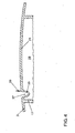
- FIG. 7 an airbag assembly according to the fourth embodiment is shown.
- the mounting holes 15 for suspending the airbag module 11 are not provided in the second wall portion 31 with increased channel cross-section, but in the first wall portion 27 with reduced cross-section in the fourth embodiment.
- the projecting through the mounting holes 15 lateral Moritagearme 13 of the airbag module 11 are not directly supported on the opening edge of the mounting holes 15. Rather, the lateral mounting arms 13 are supported with angled support legs 49 on the outside of the tapered section 29.
- the tapering section 29 therefore forms in a double function on the outside an inclined deflection 51.
- the deflection surface 51 acts in an airbag deployment with the support legs 49 of the mounting arms 13 of the airbag module 11 together so that the firing channel wall 17 is pressed inwardly against the airbag module 11 by the above-mentioned non-return movement of the airbag module 11. This reduces the mounting gap s. In this way, it is reliably prevented that the deploying airbag is partially immersed in the mounting gap s, whereby the functionality of the airbag is ensured.
Landscapes
- Engineering & Computer Science (AREA)
- Mechanical Engineering (AREA)
- Physics & Mathematics (AREA)
- Optics & Photonics (AREA)
- Plasma & Fusion (AREA)
- Air Bags (AREA)
Applications Claiming Priority (1)
| Application Number | Priority Date | Filing Date | Title |
|---|---|---|---|
| DE102008021157A DE102008021157A1 (de) | 2008-04-28 | 2008-04-28 | Airbaganordnung für ein Kraftfahrzeug |
Publications (3)
| Publication Number | Publication Date |
|---|---|
| EP2113428A2 true EP2113428A2 (fr) | 2009-11-04 |
| EP2113428A3 EP2113428A3 (fr) | 2010-01-06 |
| EP2113428B1 EP2113428B1 (fr) | 2012-08-01 |
Family
ID=41090411
Family Applications (1)
| Application Number | Title | Priority Date | Filing Date |
|---|---|---|---|
| EP09005579A Not-in-force EP2113428B1 (fr) | 2008-04-28 | 2009-04-21 | Agencement d'airbag pour un véhicule automobile |
Country Status (2)
| Country | Link |
|---|---|
| EP (1) | EP2113428B1 (fr) |
| DE (1) | DE102008021157A1 (fr) |
Cited By (4)
| Publication number | Priority date | Publication date | Assignee | Title |
|---|---|---|---|---|
| FR3014791A1 (fr) * | 2013-12-12 | 2015-06-19 | Faurecia Interieur Ind | Systeme de securite pour vehicule |
| FR3015394A1 (fr) * | 2013-12-19 | 2015-06-26 | Faurecia Interieur Ind | Procede pour fabriquer un systeme de securite pour vehicule |
| WO2016119810A1 (fr) * | 2015-01-30 | 2016-08-04 | K.L. Kaschier- Und Laminier Gmbh | Matériau composite pour cache de sac gonflable |
| CN109050460A (zh) * | 2018-09-27 | 2018-12-21 | 无锡市宏宇汽车配件制造有限公司 | 一种新型驾驶区安全包围 |
Families Citing this family (2)
| Publication number | Priority date | Publication date | Assignee | Title |
|---|---|---|---|---|
| DE102013222117A1 (de) | 2013-05-31 | 2014-12-04 | Volkswagen Aktiengesellschaft | Fahrzeuginnenverkleidung, insbesondere für einen beifahrerseitigen Armaturentafelbereich eines Kraftfahrzeugs, und Verfahren zur Herstellung einer Fahrzeuginnenverkleidung |
| US8870219B1 (en) | 2013-08-02 | 2014-10-28 | Faurecia Interior Systems, Inc. | Foam-in-place interior panels having integrated airbag doors including substrates with airbag chute-door assemblies for motor vehicles |
Citations (2)
| Publication number | Priority date | Publication date | Assignee | Title |
|---|---|---|---|---|
| DE19945022A1 (de) | 1998-09-19 | 2000-06-21 | Inova Gmbh Tech Entwicklungen | Laserbearbeitungssystem und Laserbearbeitungsverfahren für insbesondere Airbagvorrichtungsteile sowie Airbagvorrichtung |
| EP0968889B1 (fr) | 1998-07-01 | 2003-03-12 | Delphi Technologies, Inc. | Tableau de bord |
Family Cites Families (6)
| Publication number | Priority date | Publication date | Assignee | Title |
|---|---|---|---|---|
| US5322324A (en) * | 1993-08-03 | 1994-06-21 | Morton International, Inc. | Cover for an inflatable air bag housing |
| JP3321560B2 (ja) * | 1998-11-16 | 2002-09-03 | 株式会社イノアックコーポレーション | エアバッグドア部の構造 |
| DE10142598A1 (de) * | 2001-08-31 | 2003-04-10 | Opel Adam Ag | Beifahrer-Airbag-Modul für eine Armaturentafel eines Kraftfahrzeugs |
| US7434828B2 (en) * | 2005-03-22 | 2008-10-14 | Inoac Corporation | Molded member with foamed body |
| JP2007118688A (ja) * | 2005-10-26 | 2007-05-17 | Takata Corp | 内装パネルアッセンブリ及びエアバッグ装置 |
| US20080018081A1 (en) * | 2006-07-24 | 2008-01-24 | Hyundai Mobis Co., Ltd. | Air bag module for vehicles |
-
2008
- 2008-04-28 DE DE102008021157A patent/DE102008021157A1/de not_active Ceased
-
2009
- 2009-04-21 EP EP09005579A patent/EP2113428B1/fr not_active Not-in-force
Patent Citations (2)
| Publication number | Priority date | Publication date | Assignee | Title |
|---|---|---|---|---|
| EP0968889B1 (fr) | 1998-07-01 | 2003-03-12 | Delphi Technologies, Inc. | Tableau de bord |
| DE19945022A1 (de) | 1998-09-19 | 2000-06-21 | Inova Gmbh Tech Entwicklungen | Laserbearbeitungssystem und Laserbearbeitungsverfahren für insbesondere Airbagvorrichtungsteile sowie Airbagvorrichtung |
Cited By (7)
| Publication number | Priority date | Publication date | Assignee | Title |
|---|---|---|---|---|
| FR3014791A1 (fr) * | 2013-12-12 | 2015-06-19 | Faurecia Interieur Ind | Systeme de securite pour vehicule |
| FR3015394A1 (fr) * | 2013-12-19 | 2015-06-26 | Faurecia Interieur Ind | Procede pour fabriquer un systeme de securite pour vehicule |
| WO2016119810A1 (fr) * | 2015-01-30 | 2016-08-04 | K.L. Kaschier- Und Laminier Gmbh | Matériau composite pour cache de sac gonflable |
| CN106794817A (zh) * | 2015-01-30 | 2017-05-31 | K.L.复合和层压有限公司 | 用于安全气囊盖罩的复合材料 |
| US10384632B2 (en) | 2015-01-30 | 2019-08-20 | K.L. Kaschier-Und Laminier Gmbh | Composite material for an airbag cover |
| CN106794817B (zh) * | 2015-01-30 | 2021-01-05 | K.L.复合和层压有限公司 | 用于安全气囊盖罩的复合材料 |
| CN109050460A (zh) * | 2018-09-27 | 2018-12-21 | 无锡市宏宇汽车配件制造有限公司 | 一种新型驾驶区安全包围 |
Also Published As
| Publication number | Publication date |
|---|---|
| EP2113428A3 (fr) | 2010-01-06 |
| EP2113428B1 (fr) | 2012-08-01 |
| DE102008021157A1 (de) | 2009-10-29 |
Similar Documents
| Publication | Publication Date | Title |
|---|---|---|
| EP1663733B1 (fr) | Piece d'habillage interieure pour le recouvrement d'un airbag | |
| EP2113428B1 (fr) | Agencement d'airbag pour un véhicule automobile | |
| EP2113429A1 (fr) | Habillage intérieur doté d'un recouvrement d'airbag intégré | |
| DE4418582C2 (de) | Instrumententafel in einem Kraftwagen | |
| EP2006166A1 (fr) | Recouvrement d'airbag | |
| DE112014005668T5 (de) | Fahrzeuggliedanbringungsstruktur und Heckspoileranbringungsstruktur | |
| EP2006165A1 (fr) | Revêtement intérieur de véhicules à moteur avec recouvrement d'airbag intégré et son procédé de fabrication | |
| DE20023347U1 (de) | In ein Innenverkleidungsteil für Kraftfahrzeuge integriertes Airbag-System | |
| EP1436176B1 (fr) | Piece de revetement interieur pour vehicules automobiles | |
| EP3514020B1 (fr) | Dispositif guide de coussin gonflable permettant de guider un coussin gonflable d'un véhicule automobile, unité de coussin gonflable dotée d'un tel guide de coussin gonflable ainsi que pièce de revêtement intérieur et procédé de fabrication d'une pièce de revêtement intérieur correspondante comprenant un tel guide de coussin gonflable | |
| EP0537454A1 (fr) | Dispositif de sécurité | |
| EP1310698A2 (fr) | Elément déformable, notamment pour véhicules automobiles | |
| DE602004000891T2 (de) | Luftsackabdeckung | |
| WO2016045775A1 (fr) | Système de retenue d'occupant de véhicule | |
| EP2059417B1 (fr) | Recouvrement de poche a gaz | |
| DE102009058688B4 (de) | Airbaganordnung in einem Fahrzeug | |
| DE102013019940B4 (de) | Gassackabdeckung | |
| EP2563620B1 (fr) | Élément d'habillage intérieur de véhicule, et procédé de production d'un élément d'habillage intérieur de véhicule | |
| EP3947051B1 (fr) | Dispositif d'absorption d'énergie | |
| EP2015912B1 (fr) | Procede pour produire une piece moulee munie d'une rainure d'ouverture | |
| WO2003104043A1 (fr) | Piece d'equipement interieur pour automobile, notamment tableau de bord | |
| EP2558335B1 (fr) | Système d'airbag et procédé de fabrication de celui-ci | |
| EP1608537B1 (fr) | Element de revetement absorbant des chocs et destine a l'interieur de vehicules | |
| DE102006060688B4 (de) | Innenverkleidungsteil | |
| DE102006056440A1 (de) | Crash-Energieabsorber-Element, Anbindungselement mit einem solchen Crash-Engergieabsorber-Element, sowie Luftfahrzeug |
Legal Events
| Date | Code | Title | Description |
|---|---|---|---|
| PUAI | Public reference made under article 153(3) epc to a published international application that has entered the european phase |
Free format text: ORIGINAL CODE: 0009012 |
|
| AK | Designated contracting states |
Kind code of ref document: A2 Designated state(s): AT BE BG CH CY CZ DE DK EE ES FI FR GB GR HR HU IE IS IT LI LT LU LV MC MK MT NL NO PL PT RO SE SI SK TR |
|
| PUAL | Search report despatched |
Free format text: ORIGINAL CODE: 0009013 |
|
| AK | Designated contracting states |
Kind code of ref document: A3 Designated state(s): AT BE BG CH CY CZ DE DK EE ES FI FR GB GR HR HU IE IS IT LI LT LU LV MC MK MT NL NO PL PT RO SE SI SK TR |
|
| 17P | Request for examination filed |
Effective date: 20100706 |
|
| 17Q | First examination report despatched |
Effective date: 20100816 |
|
| GRAP | Despatch of communication of intention to grant a patent |
Free format text: ORIGINAL CODE: EPIDOSNIGR1 |
|
| GRAS | Grant fee paid |
Free format text: ORIGINAL CODE: EPIDOSNIGR3 |
|
| GRAA | (expected) grant |
Free format text: ORIGINAL CODE: 0009210 |
|
| RAP1 | Party data changed (applicant data changed or rights of an application transferred) |
Owner name: VOLKSWAGEN AKTIENGESELLSCHAFT |
|
| AK | Designated contracting states |
Kind code of ref document: B1 Designated state(s): AT BE BG CH CY CZ DE DK EE ES FI FR GB GR HR HU IE IS IT LI LT LU LV MC MK MT NL NO PL PT RO SE SI SK TR |
|
| REG | Reference to a national code |
Ref country code: GB Ref legal event code: FG4D Free format text: NOT ENGLISH |
|
| REG | Reference to a national code |
Ref country code: AT Ref legal event code: REF Ref document number: 568487 Country of ref document: AT Kind code of ref document: T Effective date: 20120815 Ref country code: CH Ref legal event code: EP |
|
| REG | Reference to a national code |
Ref country code: IE Ref legal event code: FG4D Free format text: LANGUAGE OF EP DOCUMENT: GERMAN |
|
| REG | Reference to a national code |
Ref country code: DE Ref legal event code: R096 Ref document number: 502009004208 Country of ref document: DE Effective date: 20120927 |
|
| REG | Reference to a national code |
Ref country code: NL Ref legal event code: VDEP Effective date: 20120801 |
|
| REG | Reference to a national code |
Ref country code: LT Ref legal event code: MG4D Effective date: 20120808 |
|
| PG25 | Lapsed in a contracting state [announced via postgrant information from national office to epo] |
Ref country code: FI Free format text: LAPSE BECAUSE OF FAILURE TO SUBMIT A TRANSLATION OF THE DESCRIPTION OR TO PAY THE FEE WITHIN THE PRESCRIBED TIME-LIMIT Effective date: 20120801 Ref country code: LT Free format text: LAPSE BECAUSE OF FAILURE TO SUBMIT A TRANSLATION OF THE DESCRIPTION OR TO PAY THE FEE WITHIN THE PRESCRIBED TIME-LIMIT Effective date: 20120801 Ref country code: IS Free format text: LAPSE BECAUSE OF FAILURE TO SUBMIT A TRANSLATION OF THE DESCRIPTION OR TO PAY THE FEE WITHIN THE PRESCRIBED TIME-LIMIT Effective date: 20121201 Ref country code: HR Free format text: LAPSE BECAUSE OF FAILURE TO SUBMIT A TRANSLATION OF THE DESCRIPTION OR TO PAY THE FEE WITHIN THE PRESCRIBED TIME-LIMIT Effective date: 20120801 Ref country code: CY Free format text: LAPSE BECAUSE OF FAILURE TO SUBMIT A TRANSLATION OF THE DESCRIPTION OR TO PAY THE FEE WITHIN THE PRESCRIBED TIME-LIMIT Effective date: 20120801 Ref country code: NO Free format text: LAPSE BECAUSE OF FAILURE TO SUBMIT A TRANSLATION OF THE DESCRIPTION OR TO PAY THE FEE WITHIN THE PRESCRIBED TIME-LIMIT Effective date: 20121101 |
|
| PG25 | Lapsed in a contracting state [announced via postgrant information from national office to epo] |
Ref country code: LV Free format text: LAPSE BECAUSE OF FAILURE TO SUBMIT A TRANSLATION OF THE DESCRIPTION OR TO PAY THE FEE WITHIN THE PRESCRIBED TIME-LIMIT Effective date: 20120801 Ref country code: PT Free format text: LAPSE BECAUSE OF FAILURE TO SUBMIT A TRANSLATION OF THE DESCRIPTION OR TO PAY THE FEE WITHIN THE PRESCRIBED TIME-LIMIT Effective date: 20121203 Ref country code: PL Free format text: LAPSE BECAUSE OF FAILURE TO SUBMIT A TRANSLATION OF THE DESCRIPTION OR TO PAY THE FEE WITHIN THE PRESCRIBED TIME-LIMIT Effective date: 20120801 Ref country code: GR Free format text: LAPSE BECAUSE OF FAILURE TO SUBMIT A TRANSLATION OF THE DESCRIPTION OR TO PAY THE FEE WITHIN THE PRESCRIBED TIME-LIMIT Effective date: 20121102 Ref country code: SI Free format text: LAPSE BECAUSE OF FAILURE TO SUBMIT A TRANSLATION OF THE DESCRIPTION OR TO PAY THE FEE WITHIN THE PRESCRIBED TIME-LIMIT Effective date: 20120801 Ref country code: SE Free format text: LAPSE BECAUSE OF FAILURE TO SUBMIT A TRANSLATION OF THE DESCRIPTION OR TO PAY THE FEE WITHIN THE PRESCRIBED TIME-LIMIT Effective date: 20120801 |
|
| PG25 | Lapsed in a contracting state [announced via postgrant information from national office to epo] |
Ref country code: NL Free format text: LAPSE BECAUSE OF FAILURE TO SUBMIT A TRANSLATION OF THE DESCRIPTION OR TO PAY THE FEE WITHIN THE PRESCRIBED TIME-LIMIT Effective date: 20120801 |
|
| PG25 | Lapsed in a contracting state [announced via postgrant information from national office to epo] |
Ref country code: ES Free format text: LAPSE BECAUSE OF FAILURE TO SUBMIT A TRANSLATION OF THE DESCRIPTION OR TO PAY THE FEE WITHIN THE PRESCRIBED TIME-LIMIT Effective date: 20121112 Ref country code: DK Free format text: LAPSE BECAUSE OF FAILURE TO SUBMIT A TRANSLATION OF THE DESCRIPTION OR TO PAY THE FEE WITHIN THE PRESCRIBED TIME-LIMIT Effective date: 20120801 Ref country code: EE Free format text: LAPSE BECAUSE OF FAILURE TO SUBMIT A TRANSLATION OF THE DESCRIPTION OR TO PAY THE FEE WITHIN THE PRESCRIBED TIME-LIMIT Effective date: 20120801 Ref country code: RO Free format text: LAPSE BECAUSE OF FAILURE TO SUBMIT A TRANSLATION OF THE DESCRIPTION OR TO PAY THE FEE WITHIN THE PRESCRIBED TIME-LIMIT Effective date: 20120801 Ref country code: CZ Free format text: LAPSE BECAUSE OF FAILURE TO SUBMIT A TRANSLATION OF THE DESCRIPTION OR TO PAY THE FEE WITHIN THE PRESCRIBED TIME-LIMIT Effective date: 20120801 |
|
| PG25 | Lapsed in a contracting state [announced via postgrant information from national office to epo] |
Ref country code: SK Free format text: LAPSE BECAUSE OF FAILURE TO SUBMIT A TRANSLATION OF THE DESCRIPTION OR TO PAY THE FEE WITHIN THE PRESCRIBED TIME-LIMIT Effective date: 20120801 Ref country code: IT Free format text: LAPSE BECAUSE OF FAILURE TO SUBMIT A TRANSLATION OF THE DESCRIPTION OR TO PAY THE FEE WITHIN THE PRESCRIBED TIME-LIMIT Effective date: 20120801 |
|
| PLBE | No opposition filed within time limit |
Free format text: ORIGINAL CODE: 0009261 |
|
| STAA | Information on the status of an ep patent application or granted ep patent |
Free format text: STATUS: NO OPPOSITION FILED WITHIN TIME LIMIT |
|
| 26N | No opposition filed |
Effective date: 20130503 |
|
| PG25 | Lapsed in a contracting state [announced via postgrant information from national office to epo] |
Ref country code: BG Free format text: LAPSE BECAUSE OF FAILURE TO SUBMIT A TRANSLATION OF THE DESCRIPTION OR TO PAY THE FEE WITHIN THE PRESCRIBED TIME-LIMIT Effective date: 20121101 |
|
| REG | Reference to a national code |
Ref country code: DE Ref legal event code: R097 Ref document number: 502009004208 Country of ref document: DE Effective date: 20130503 |
|
| BERE | Be: lapsed |
Owner name: VOLKSWAGEN A.G. Effective date: 20130430 |
|
| PG25 | Lapsed in a contracting state [announced via postgrant information from national office to epo] |
Ref country code: MC Free format text: LAPSE BECAUSE OF FAILURE TO SUBMIT A TRANSLATION OF THE DESCRIPTION OR TO PAY THE FEE WITHIN THE PRESCRIBED TIME-LIMIT Effective date: 20120801 |
|
| REG | Reference to a national code |
Ref country code: CH Ref legal event code: PL |
|
| REG | Reference to a national code |
Ref country code: IE Ref legal event code: MM4A |
|
| PG25 | Lapsed in a contracting state [announced via postgrant information from national office to epo] |
Ref country code: BE Free format text: LAPSE BECAUSE OF NON-PAYMENT OF DUE FEES Effective date: 20130430 Ref country code: LI Free format text: LAPSE BECAUSE OF NON-PAYMENT OF DUE FEES Effective date: 20130430 Ref country code: CH Free format text: LAPSE BECAUSE OF NON-PAYMENT OF DUE FEES Effective date: 20130430 |
|
| PG25 | Lapsed in a contracting state [announced via postgrant information from national office to epo] |
Ref country code: IE Free format text: LAPSE BECAUSE OF NON-PAYMENT OF DUE FEES Effective date: 20130421 |
|
| PG25 | Lapsed in a contracting state [announced via postgrant information from national office to epo] |
Ref country code: MT Free format text: LAPSE BECAUSE OF FAILURE TO SUBMIT A TRANSLATION OF THE DESCRIPTION OR TO PAY THE FEE WITHIN THE PRESCRIBED TIME-LIMIT Effective date: 20120801 |
|
| REG | Reference to a national code |
Ref country code: AT Ref legal event code: MM01 Ref document number: 568487 Country of ref document: AT Kind code of ref document: T Effective date: 20140421 |
|
| PG25 | Lapsed in a contracting state [announced via postgrant information from national office to epo] |
Ref country code: TR Free format text: LAPSE BECAUSE OF FAILURE TO SUBMIT A TRANSLATION OF THE DESCRIPTION OR TO PAY THE FEE WITHIN THE PRESCRIBED TIME-LIMIT Effective date: 20120801 |
|
| PG25 | Lapsed in a contracting state [announced via postgrant information from national office to epo] |
Ref country code: MK Free format text: LAPSE BECAUSE OF FAILURE TO SUBMIT A TRANSLATION OF THE DESCRIPTION OR TO PAY THE FEE WITHIN THE PRESCRIBED TIME-LIMIT Effective date: 20120801 Ref country code: HU Free format text: LAPSE BECAUSE OF FAILURE TO SUBMIT A TRANSLATION OF THE DESCRIPTION OR TO PAY THE FEE WITHIN THE PRESCRIBED TIME-LIMIT; INVALID AB INITIO Effective date: 20090421 Ref country code: LU Free format text: LAPSE BECAUSE OF NON-PAYMENT OF DUE FEES Effective date: 20130421 |
|
| PG25 | Lapsed in a contracting state [announced via postgrant information from national office to epo] |
Ref country code: AT Free format text: LAPSE BECAUSE OF NON-PAYMENT OF DUE FEES Effective date: 20140421 |
|
| REG | Reference to a national code |
Ref country code: FR Ref legal event code: PLFP Year of fee payment: 8 |
|
| REG | Reference to a national code |
Ref country code: FR Ref legal event code: PLFP Year of fee payment: 9 |
|
| REG | Reference to a national code |
Ref country code: FR Ref legal event code: PLFP Year of fee payment: 10 |
|
| P01 | Opt-out of the competence of the unified patent court (upc) registered |
Effective date: 20230523 |
|
| PGFP | Annual fee paid to national office [announced via postgrant information from national office to epo] |
Ref country code: FR Payment date: 20230421 Year of fee payment: 15 Ref country code: DE Payment date: 20230430 Year of fee payment: 15 |
|
| PGFP | Annual fee paid to national office [announced via postgrant information from national office to epo] |
Ref country code: GB Payment date: 20230418 Year of fee payment: 15 |
|
| REG | Reference to a national code |
Ref country code: DE Ref legal event code: R119 Ref document number: 502009004208 Country of ref document: DE |
|
| GBPC | Gb: european patent ceased through non-payment of renewal fee |
Effective date: 20240421 |
|
| PG25 | Lapsed in a contracting state [announced via postgrant information from national office to epo] |
Ref country code: DE Free format text: LAPSE BECAUSE OF NON-PAYMENT OF DUE FEES Effective date: 20241105 |
|
| PG25 | Lapsed in a contracting state [announced via postgrant information from national office to epo] |
Ref country code: GB Free format text: LAPSE BECAUSE OF NON-PAYMENT OF DUE FEES Effective date: 20240421 |
|
| PG25 | Lapsed in a contracting state [announced via postgrant information from national office to epo] |
Ref country code: FR Free format text: LAPSE BECAUSE OF NON-PAYMENT OF DUE FEES Effective date: 20240430 |
|
| PG25 | Lapsed in a contracting state [announced via postgrant information from national office to epo] |
Ref country code: GB Free format text: LAPSE BECAUSE OF NON-PAYMENT OF DUE FEES Effective date: 20240421 Ref country code: FR Free format text: LAPSE BECAUSE OF NON-PAYMENT OF DUE FEES Effective date: 20240430 Ref country code: DE Free format text: LAPSE BECAUSE OF NON-PAYMENT OF DUE FEES Effective date: 20241105 |