EP2113449A2 - Stellgliedsteuervorrichtung, Stellgliedsteuerverfahren, Stellglied, Robotervorrichtung und Computerprogramm - Google Patents
Stellgliedsteuervorrichtung, Stellgliedsteuerverfahren, Stellglied, Robotervorrichtung und Computerprogramm Download PDFInfo
- Publication number
- EP2113449A2 EP2113449A2 EP09156337A EP09156337A EP2113449A2 EP 2113449 A2 EP2113449 A2 EP 2113449A2 EP 09156337 A EP09156337 A EP 09156337A EP 09156337 A EP09156337 A EP 09156337A EP 2113449 A2 EP2113449 A2 EP 2113449A2
- Authority
- EP
- European Patent Office
- Prior art keywords
- joint
- actuator
- force
- value
- torque
- Prior art date
- Legal status (The legal status is an assumption and is not a legal conclusion. Google has not performed a legal analysis and makes no representation as to the accuracy of the status listed.)
- Withdrawn
Links
Images


Classifications
-
- B—PERFORMING OPERATIONS; TRANSPORTING
- B25—HAND TOOLS; PORTABLE POWER-DRIVEN TOOLS; MANIPULATORS
- B25J—MANIPULATORS; CHAMBERS PROVIDED WITH MANIPULATION DEVICES
- B25J9/00—Program-controlled manipulators
- B25J9/16—Program controls
- B25J9/1628—Program controls characterised by the control loop
- B25J9/1633—Program controls characterised by the control loop compliant, force, torque control, e.g. combined with position control
-
- G—PHYSICS
- G05—CONTROLLING; REGULATING
- G05B—CONTROL OR REGULATING SYSTEMS IN GENERAL; FUNCTIONAL ELEMENTS OF SUCH SYSTEMS; MONITORING OR TESTING ARRANGEMENTS FOR SUCH SYSTEMS OR ELEMENTS
- G05B2219/00—Program-control systems
- G05B2219/30—Nc systems
- G05B2219/39—Robotics, robotics to robotics hand
- G05B2219/39319—Force control, force as reference, active compliance
-
- G—PHYSICS
- G05—CONTROLLING; REGULATING
- G05B—CONTROL OR REGULATING SYSTEMS IN GENERAL; FUNCTIONAL ELEMENTS OF SUCH SYSTEMS; MONITORING OR TESTING ARRANGEMENTS FOR SUCH SYSTEMS OR ELEMENTS
- G05B2219/00—Program-control systems
- G05B2219/30—Nc systems
- G05B2219/39—Robotics, robotics to robotics hand
- G05B2219/39355—Observer, disturbance observer
-
- Y—GENERAL TAGGING OF NEW TECHNOLOGICAL DEVELOPMENTS; GENERAL TAGGING OF CROSS-SECTIONAL TECHNOLOGIES SPANNING OVER SEVERAL SECTIONS OF THE IPC; TECHNICAL SUBJECTS COVERED BY FORMER USPC CROSS-REFERENCE ART COLLECTIONS [XRACs] AND DIGESTS
- Y10—TECHNICAL SUBJECTS COVERED BY FORMER USPC
- Y10T—TECHNICAL SUBJECTS COVERED BY FORMER US CLASSIFICATION
- Y10T74/00—Machine element or mechanism
- Y10T74/20—Control lever and linkage systems
- Y10T74/20207—Multiple controlling elements for single controlled element
- Y10T74/20305—Robotic arm
- Y10T74/20317—Robotic arm including electric motor
Definitions
- the present invention relates to an actuator control device and an actuator control method which control actuators used for driving or the like of joint parts of a robot, an actuator, a robot apparatus, and a computer program, and particularly, to an actuator control device and an actuator control method which control driving of joint actuators by a force control method which directly controls a joint generation force, an actuator, a robot apparatus, and a computer program.
- the present invention relates to an actuator control device and an actuator control method which perform force control suitable for physical interaction with a human being while coping with factors of disturbances whose modeling or identifying is difficult, such as friction or inertia, which exists in joint parts, an actuator, a robot apparatus, and a computer program, and particularly, to an actuator control device and an actuator control method which perform force control suitable for physical interaction with a human being while coping with a disturbance problem by calculating a joint force for generating a desired force in a predetermined part of a body while the dynamics of the robot is taken into consideration, an actuator, a robot apparatus, and a computer program.
- an odor emission source detecting and eliminating apparatus which can be utilized for immediately sanitary removal of excrement which may cause odors in elderly people nursing-care facilities, hospitals, etc., and cause hospital infections (for example, refer to JP-A-2005-61836 ).
- an action expression system is suggested which makes the action of an elderly person expressed by a robot at a close relative's house on the basis of a first detection result obtained by detecting the action of the elderly person, estimates the degree of interest of the close relative from a second detection result obtained by detecting the watching action of the close relative, and feeds back the result to give a change to the action expression of the robot (for example, refer to JP-A-2006-178644 ).
- the mechatronics instruments to be applied in the field as described above should execute a task while making physical contact with people or complicated actual environments flexibly and safely. That is, unlike the fact that related-art industrial robots performed fixed motions under a known environment, the inventors consider that the above mechatronics instruments should sense an unknown environment and obtain a proper external force from surrounding environments which vary every moment, thereby properly adjusting the generation forces of actuators so that a desired task may be achieved.
- the robot is basically a multi-link structure including joints which are a plurality of links and link movable portions, and is adapted so as to drive each joint by using an actuator including a DC brushless motor or the like.
- the method of controlling such a robot includes, for example, positional control and force control.
- the positional control is a control method of driving the joint so as to give a position command value, such as an angle, to the actuator and follow the command value.
- the other force control is a control method of directly receiving a target value of the force to be applied to an operation object and realizing the force indicated by the target value, and can directly control a joint generation force and directly control a force.
- positional control is commonly called “hard control” because its basic purpose is to hold a position, and is not suitable for responding to an external force flexibly or for precisely performing "soft" control in terms of velocity or acceleration.
- robot apparatuses which execute a task while performing physical interaction with various outsides originally have low compatibility with the positional control.
- Parameters which determine the dynamics of the robot are classified roughly into mass properties, such as link weight, center of gravity, and inertia tensor, and the friction and inertia inside a joint.
- the former mass properties can be calculated relatively easily and with high precision on the basis of CAD (Computer Aided Design) data.
- CAD Computer Aided Design
- a method of coping with the disturbance problem in the force control can be classified roughly into following three methods.
- the first method includes using a direct drive motor (for example, refer to JP-A-2007-124856 ) or a configuration (for example, refer to USP No. 5587937 ) which performs deceleration of a low reduction gear ratio using a wire mechanism.
- a direct drive motor for example, refer to JP-A-2007-124856
- a configuration for example, refer to USP No. 5587937
- a method of arranging a force sensor at a working point of a force, feeding back the deviation between a generation force and a force command value to a joint command value, and suppressing a disturbance exerted on the generation force at the action point is conceivable (for example, refer to " Robust Motion Control by Disturbance Observer” (Journal of Robotics Society of Japan, Vol. 11, No.4, pp. 486-493, 1993) by Onishi ).
- this method it becomes possible to suppress all disturbances, such as a disturbance force received from a cable as well as the disturbance inside the joint, whereas there is a constraint that interaction is limited to a part in which the force sensor is set. In other words, in order to allow interaction in an arbitrary part of a whole body, expensive force sensors should be mounted in various places of the body.
- a control system which determines generation force target values of all actuators by detecting contact parts with the outside without omission, using contact sensors arranged in a distributed manner over the whole body surface of a link structure, such as a robot, and by exactly solving a mechanical model so that a desired motion may be achieved, while properly using external forces having the detected contact parts as points of action.
- favorable tactile force interaction in which points of action are not limited can be realized by compensating a force, which is difficult to model, within each joint which connects between links by a torque sensor provided at a joint part.
- the precision of a generation force also becomes favorable. It becomes possible to utilize a reducer, and it also becomes possible to obtain a large joint force by a small motor. Additionally, since the force feedback from a force sensor is not used, it is also not necessary to mount force sensors in various places.
- actuator control device and actuator control method which can suitably control driving of joint actuators by a force control method which directly controls a joint generation force, an actuator, a robot apparatus, and a computer program.
- actuator control device and actuator control method which can favorably perform force control suitable for physical interaction with a human being while coping with factors of disturbances whose modeling or identifying is difficult, such as friction or inertia, which exists in joint parts, an actuator, a robot apparatus, and a computer program.
- an actuator control device for force-controlling a joint driving actuator according to a commanded joint force command value ⁇ a .
- the actuator control device includes a joint value detecting means for detecting a joint value q at an output stage of the actuator, an action force detecting means for detecting an action force ⁇ e in a joint driving direction at the output stage of the actuator, and a driving force determining means for determining an instructed driving force ⁇ to the actuator, on the basis of an ideal response model of the actuator which specifies the relationship of a joint value acceleration target value achieved as the actuator responds ideally when the joint force command value ⁇ a , the action force ⁇ e , and a joint value velocity obtained by time-differentiating the joint value q are given.
- the force control tends to be influenced by a disturbance and has a problem that a system configuration is complicated.
- the main factors of the disturbance are friction and inertia which exist in a joint part, and since modeling and identifying of the friction and inertia are difficult, there is a possibility that a large error is invited.
- the actuator control device controls driving of a joint actuator by a force control method
- an attempt to deal with the disturbance problem is made by calculating a joint force for generating a desired force in a predetermined part of the body while the dynamics of the robot is taken into consideration.
- this coping method since errors of parameters other than parameters inside a joint can generally be made small, the precision of a generation force also becomes favorable. It becomes possible to utilize a reducer, and it also becomes possible to obtain a large joint force by a small motor. Additionally, since the force feedback from a force sensor is not used, it is also not necessary to mount force sensors in various places.
- the actuator control device is adapted to determine the driving force ⁇ to be assigned to a joint on the basis of an ideal response model of an actuator when the device force-controls the joint driving actuator according to the commanded joint force command value ⁇ a .
- the expression "ideal response model” is configured by a secondary differential equation that specifies the relationship of a joint value acceleration target value achieved as the actuator responds ideally when the joint force command value ⁇ a , the action force ⁇ e , and a joint value velocity obtained by time-differentiating the joint value q are given.
- the actuator control device includes a joint value detecting means, including an encoder or the like, for detecting a joint value q at an output stage of the actuator, an action force detecting means, such as a torque sensor, which detects an action force ⁇ e in a joint driving direction at the output stage of the actuator, and uses these detection results as inputs when the driving force ⁇ is determined.
- a joint value detecting means including an encoder or the like, for detecting a joint value q at an output stage of the actuator
- an action force detecting means such as a torque sensor, which detects an action force ⁇ e in a joint driving direction at the output stage of the actuator, and uses these detection results as inputs when the driving force ⁇ is determined.
- the ideal response model of the actuator including a secondary differential equation shall include a virtual inertia or a virtual viscous resistance coefficient ⁇ a which acts according to the magnitude of the joint value velocity obtained by time-differentiating the joint value q.
- the expression "virtual inertia or virtual viscous resistance coefficient ⁇ a " is a parameter of dynamics, included inside a joint, whose modeling is difficult, and becomes a key factor of a disturbance.
- the driving force determining means can suppress influence of the disturbance to determine the driving force ⁇ with high precision.
- the driving force determining means is adapted to apply a disturbance observer to remove influence of a disturbance resulting from friction or inertia, etc. inside a joint whose modeling becomes difficult, and can determine the driving force ⁇ of the actuator with high precision in conformity with the theoretical response model.
- the disturbance observer is adapted to estimate a driving force which has acted on the joint on the basis of the joint value velocity obtained by time-differentiating the joint value q detected by the joint value detecting means when the joint actuator is driven by the driving force ⁇ determined by the driving force determining means, and subtract the estimated driving force from the driving force ⁇ to calculate a disturbance joint force ⁇ d .
- the driving force determining means can correct a joint force target value ⁇ ref , which is based on the joint value acceleration target value obtained from the ideal response model, by the disturbance joint force ⁇ d obtained by the disturbance observer in a previous control cycle, and determine the driving force ⁇ in the current control cycle.
- a computer program described in a computer readable format so as to execute processing for force-controlling a joint driving actuator according to a commanded joint force command value ⁇ a on a computer.
- the program causes the computer to function as a joint value detecting means for detecting a joint value q at an output stage of the actuator, an action force detecting means for detecting an action force ⁇ e in a joint driving direction at the output stage of the actuator, and a driving force determining means for determining an instructed driving force ⁇ to the actuator, on the basis of an ideal response model of the actuator which specifies the relationship of a joint value acceleration target value achieved as the actuator responds ideally when the joint force command value ⁇ a , the action force ⁇ e , and a joint value velocity obtained by time-differentiating the joint value q are given.
- the computer program according to the second embodiment of the present invention defines a computer program stated in a computer-readable format so as to realize predetermined processing on a computer.
- a computer program stated in a computer-readable format so as to realize predetermined processing on a computer.
- the actuator control device can be applied to force control of at least some joint actuators, in a robot apparatus including a link structure constructed by connecting a plurality of rigid body links, and joint actuators which drive joints which connect between the links.
- a robot apparatus including a link structure constructed by connecting a plurality of rigid body links, and joint actuators which drive joints which connect between the links.
- an actuator behaves ideally so that friction and inertia of a joint part which become key factors of errors match a theoretical model.
- an actuator generally includes a reducer, and errors, such as unknown friction, exist inside a joint, the force control can be realized suitably if an ideal response of the joint actuator is achieved by the present invention.
- actuator control device and actuator control method which can favorably perform force control suitable for physical interaction with a human being while coping with factors of disturbances whose modeling or identifying is difficult, such as friction or inertia, which exists in joint parts, an actuator, a robot apparatus, and a computer program.
- actuator control device and actuator control method which can favorably perform force control suitable for physical interaction with a human being while coping with a disturbance problem by calculating a joint force for generating a desired force in a predetermined part of a body while the dynamics of the robot is taken into consideration, an actuator, a robot apparatus, and a computer program.
- an ideal (in other words, virtualized) actuator which behaves as a theoretical model can be constructed. Accordingly, by applying the ideal actuator to a joint of a robot, it is possible to solve a disturbance problem in the force control by a method of calculating a joint force for generating a desired force in a predetermined part of the body while the dynamics of the robot is taken into consideration. As a result, it is possible to provide a robot which can perform flexible force interaction with a human being and an environment in an arbitrary part. Additionally, even if an hexa-axial force sensor is not arranged over the whole body of a robot, the control of generation force, acceleration, speed, and position in an arbitrary parts of the body can be performed favorably.
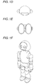
- a front view, a left side view, a back view, a top view, a bottom view, and a perspective view of a humanoid robot to which the invention can be applied are shown in Figs. 1A to L
- a front view, a left side view, a back view, a top view, a bottom view, and a perspective view of a head part of the robot are respectively shown in Figs. 1A to 1L
- a joint degree-of-freedom model of the humanoid robot shown in Figs. 1A to 1L is shown in Fig. 2 .
- an upper body is connected to a pelvic part via two leg bodies as a moving means, and a waist joint.
- Two arm parts are connected to the upper body, and a head part is connected to the upper body via a neck joint.
- the right and left leg bodies are provided with a total of six degrees of freedom including three degrees of freedom of a hip joint, one degree of freedom of a knee joint, and two degrees of freedom of an ankle joint, respectively. Additionally, the right and left arm parts are provided with a total of six degrees of freedom including three degrees of freedom of a shoulder joint, one degree of freedom of an elbow joint, and two degrees of freedom of a wrist joint, respectively. Both the neck joint and the waist joint have three degrees of freedom around X, Y, and the Z axes.
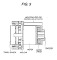
- Fig. 3 shows a configuration of an actuator which drives each joint shaft.
- the illustrated actuator includes a motor (for example, a DC brushless motor) for generating rotary torque, an electric current control type motor driver for driving the motor, and a reducer for converting a rotary force of the motor into a sufficient generation force. Additionally, an encoder for measuring a joint angle and a torque sensor which detects the rotary torque are attached to an output shaft of the reducer. It should be noted that parameters of dynamics, such as friction or inertia, whose modeling or identifying becomes difficult, are included in a joint part.
- FIG. 4A A configuration of the torque sensor attached to the output shaft of the reducer is shown in Fig. 4A .
- the illustrated torque sensor has a rare distorted structure, and has a configuration in which the volume of infinitesimal deformation is measured by two pairs of strain gauges A to D which are stuck on a beam portion so as to face each other.
- An equivalent circuit of the torque sensor is shown in Fig. 4B .
- the volume of deformation is measured as a potential difference approximately proportional to ⁇ e at both ends of a bridge circuit including resistors A to D.
- Such torque measurement results are collected by a microcomputer for control set in the actuator, and are then transmitted to a host computer (which will be described later).
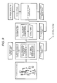
- Fig. 5 shows a configuration of the connection topology in the humanoid robot shown in Figs. 1A to 1L .
- Each joint driving actuator is connected with a host computer which generally controls the whole operation of the humanoid robot, so that torque control target value thereof can be given from the host computer, and a current output torque, a current joint angle or a current joint angular velocity can be transmitted to the host computer.
- the humanoid robot has triaxial waist joint actuators a1, a2, a3, and triaxial neck joint actuators a16, a17, and a18 in a body part, and these actuators are serially connected to the host computer. Additionally, the torque sensors tq16, tq17, and tq18 shown in Fig. 4A are arranged between an output shaft of each of the actuator motors a16, a17, and a18, and the frame. Each joint actuator receives a positional control target value thereof through a serial cable, and transmits a current output torque, a joint angle, and a joint angular velocity to the host computer.
- the humanoid robot has triaxial shoulder joint actuators a4, a5, and a6, a uniaxial elbow joint actuator a7, and biaxial wrist joint actuators a8 and a9 in a left arm part, torque sensors tq4, tq5, tq6, tq7, tq8, and tq9 shown in Fig. 4A are arranged between an output shaft of each of the actuator motors a4, a5, a6, a7, a8, and a9, and the frame, and these torque sensors are serially connected to the host computer.
- the humanoid robot has triaxial shoulder joint actuators a10, a11, and a12, a uniaxial elbow joint actuator a13, and biaxial wrist joint actuators a14 and a15 in a right arm part, torque sensors tq10, tq11, tq12, tq13, tq14, and tq15 shown in Fig. 4A are arranged between an output shaft of each of the actuator motors a 10, a11, a12, a13, a14, and a15, and the frame, and these torque sensors are serially connected to the host computer.
- the humanoid robot has triaxial hip joint actuators a19, a20, and a21, a uniaxial knee joint actuator a22, and biaxial ankle joint actuators a23 and a24 in a left leg part, torque sensors tq19, tq20, tq21, tq22, tq23, and tq24 shown in Fig. 4A are arranged between an output shaft of each of the actuator motors a19, a20, a21, a22, a23, and a24, and the frame, and these torque sensors are serially connected to the host computer.
- the humanoid robot has triaxial hip joint actuators a25, a26, and a27, a uniaxial knee joint actuator a28, and biaxial ankle joint actuators a29 and a30 in a right leg part, torque sensors tq25, tq26, tq27, tq28, tq29, and tq30 shown in Fig. 4A are arranged between an output shaft of each of the actuator motors a25, a26, a27, a28, a29, and a30, and the frame, and these torque sensors are serially connected to the host computer.
- the dynamics operation of the robot is executed on the host computer to generate the torque target value of each joint actuator.
- the torque target value is transmitted to a control microcomputer juxtaposed to the actuator, and is used for control of the actuator executed on the control microcomputer. Additionally, each joint actuator is controlled by a force control method.
- an attempt to deal with the disturbance problem is made by the third method of calculating a joint force for generating a desired force in a predetermined part of the body while the dynamics of the robot is taken into consideration. In such a case, it becomes unnecessary to dispose a hexa-axial force sensor in any parts of the body.
- I a is the virtual inertia of a joint
- q is the joint angle of the joint (obtained as an encoder output)
- ⁇ a is a command value of the generation torque of the joint
- ⁇ e is an external torque exerted by the joint
- ⁇ a is an unknown virtual viscosity coefficient (whose modeling becomes difficult) inside the joint.
- the fact that the actuator performs the response according to the theoretical model expressed by the above Expression (1) means that the joint angle acceleration at the left side of the above Expression (1) is attained when the right side of the Expression is given.
- the joint torque ⁇ is determined with high precision on the basis of a theoretical response model by applying a disturbance observer which estimates disturbance torque.
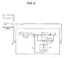
- FIG. 6 A control block diagram of the joint angle acceleration control system for performing the response according to the theoretical model is shown in Fig. 6 .
- a portion surrounded by a dotted line is equivalent to the disturbance observer, and a robust acceleration control system is built by estimating a disturbance torque ⁇ d and removing the influence which affects the control system.
- J n is defined as a nominal value of the inertia within the joint
- J is defined as an (unknown) actual value of the inertia within the joint
- q is defined as the joint angle.
- the virtual inertia I a of the joint it is assumed that an virtual constant is given as a design item in the dynamics operation.
- a torque command value ⁇ a for the actuator is determined in every control cycle by the force control method, an external torque actual measurement value ⁇ e measured by the torque sensor (refer to Fig. 4B ) attached to the output shaft of the reducer of the actuator, and an angular velocity actual measurement value obtained from the joint angle q measured by the encoder attached to the output shaft of the reducer are sent from the control microcomputer within the actuator.
- the torque command value ⁇ a the external torque actual measurement value ⁇ e , and the angular velocity actual measurement value of the joint angle q are assigned to the theoretical response model expressed by the above Expression (1), an acceleration target value of the joint angle q at the left side of this numerical expression is calculated, and the angular acceleration target value is input to the disturbance observer.
- the input acceleration target value of the joint angle q is multiplied by the virtual inertia nominal value J n of the joint, and the resulting value is converted into the torque target value ⁇ ref in a current control cycle. Then, when the torque target value ⁇ ref is corrected by the disturbance torque ⁇ d obtained in the previous control cycle by the disturbance observer, the torque command value ⁇ for the joint in the current control cycle is obtained.
- the joint is rotationally driven while being influenced by disturbance, such as friction or inertia, which exists in the joint part.
- the torque command value ⁇ is converted into an electric current command value, and, this converted value is used as an instruction input to the motor driver.
- the generation torque ⁇ e and the joint angle q in that case are measured by the torque sensor and the encoder, respectively, and the joint angular velocity is obtained by time-differentiating the encoder output q.
- the disturbance observer can estimate the torque which has acted on the joint by applying the transfer coefficient J n s including the virtual inertia nominal value J n of the joint to the angular velocity of the measured joint angle q, and can estimate the disturbance torque ⁇ d by subtracting the estimated torque from the torque command value ⁇ to the joint. Also, the disturbance torque ⁇ d obtained in the current control cycle is fed back, and is used for correction of the torque command value ⁇ in the next control cycle (same as the above). In addition, a low pass filter (LPF) expressed by g/(s+g) which has been inserted on the way is used to prevent the divergence of the system.
- LPF low pass filter
- the acceleration response of the actuator can be made to follow the acceleration target value. That is, when the right side of the above Expression (1) is given, the joint angle acceleration at the left side is attained.
- the response according to the theoretical model can be realized irrespective of the actuator being influenced by a disturbance.
- the above low pass filter g/(s+g) which feeds back the disturbance torque ⁇ d is inserted (as mentioned above), and is not fit for removal of a disturbance in a high frequency region.
- the disturbance observer estimates an external disturbance component in a plant, and feeds back the component as a control input, whereby it is effective to reach a target state even if an unknown parameter change or an unknown disturbance is in the plant.
- the disturbance observer estimates an external disturbance component in a plant, and feeds back the component as a control input, whereby it is effective to reach a target state even if an unknown parameter change or an unknown disturbance is in the plant.
- it is necessary to repeat feedback operation in a plurality of cycles.
- the disturbance observer obtains the angular acceleration of the joint angle q according to the above Expression (1), and sets this acceleration to a joint angle acceleration target value for a joint actuator.
- the angular acceleration of the joint angle q is determined on the basis of the external torque ⁇ e obtained from the torque sensor attached to the output shaft of the reducer, the generation torque ⁇ a of the joint, and the time differential of the joint angle q output from the encoder attached to the output shaft of the reducer.
- the actuator control as shown in Fig. 6 for realizing an ideal joint angle acceleration response by using the control system using the disturbance observer can be configured by relatively simple processing operation, and can be executed at a high sampling rate (for example, in a cycle of 100 microseconds) independently on a control microcomputer which is juxtaposed to each actuator.
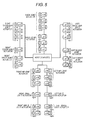
- FIG. 8 A processing sequence of operation which realizes an ideal joint angle acceleration response is shown in the form of a flow chart in Fig. 8 .
- Step S1 the value of a torque sensor attached to an output shaft of a reducer of an actuator is measured, and an external torque ⁇ e is obtained (Step S1).
- Step S2 the value of an encoder attached to the output shaft of the reducer of the actuator is measured, and a joint angle q is obtained (Step S2). Further, the joint angle q is time-differentiated, and a joint angular velocity is obtained.
- a joint angle acceleration target value of the joint angle q is calculated using the above Expression (1) (Step S3). That is, the following Expression (2) is calculated.
- q ⁇ ref ⁇ a - ⁇ e - ⁇ a ⁇ q ⁇ / I a
- a disturbance torque ⁇ d is obtained by a disturbance observer (Step S4).
- a disturbance torque ⁇ d is calculated by the following Expression (3) from Fig. 6 .
- a torque command value ⁇ in this expression is defined as a torque command value in a previous control cycle.
- a torque command value ⁇ in a current control cycle can be obtained by converting a joint angle acceleration obtained from the above Expression (2) in Step S2 into a torque target value ⁇ ref , and by adding a disturbance torque ⁇ d obtained from the torque target value ⁇ ref by the above Expression (3).
- ⁇ J n ⁇ q ⁇ ref + ⁇ d
- an electric current command value i ref to the motor driver is calculated by dividing the torque command value ⁇ obtained from the above Expression (4) by a torque constant K t (Step S5).
- i ref ⁇ / K t
- a bipedal walking mobile robot is expressed as an open link tree structure with a pelvis B as a basis.
- the robot can move freely in a world space, and can change its posture.
- a generalized variable q representing the whole posture of the robot can be expressed like the following Expression (6), using a vector e in which all joint values serving as the current states of actuators can be enumerated, and a vector in which the posture ⁇ and position p 0 of a base are enumerated as the motion state of the robot.
- q ⁇ ⁇ p 0 ⁇ ⁇ T
- the operational space is a space for describing the relationship between a force acting on the robot, and acceleration to be generated.
- the operational space becomes indispensable when a contact way between the robot and an environment is used as constraint conditions when joint angles of the robot are not position-controlled, but force-controlled.
- a generalized variable In a link structure in which a rigid body link is connected via joints, a vector in which all values of the joints can be enumerated is called a generalized variable, and is expressed by q.
- the Cartesian coordinate system for execution of a task is an example of the operational space.
- a task such as a finger position posture at the tip of a manipulator
- the operational space As for the basic idea of the operational space, refer to, for example, " A unified approach to motion and force control of robot manipulators" (The operational space formulation, IEEE Journal of Robotics and Automation, and RA-3 (1), pp.43-53, 1987 ).
- ⁇ a generalized force corresponding to the generalized variable q
- b the gravitational force/Coriolis force
- f an external force acting on the operational space.
- a -1 is called an operational space inertia inverse matrix, and is expressed like the following Expression (10).
- H is an inertia matrix for a joint space of the whole structure.
- c of a third term of a right side of the above Expression (9) is equivalent to an operational space bias acceleration (that is, the acceleration acting on an operational space in a case where an external force does not act), and is expressed like the following Expression (11).
- c JH - 1 ⁇ ⁇ - b + J ⁇ ⁇ q ⁇
- the operational space i.e., the relationship between acceleration and a force are given by an operational space inertia inverse matrix.
- an inertia matrix H for a joint space of the whole structure is interposed, and thus, needless calculation is made. Therefore, a great amount of calculation is needed in the calculation of the operational space inertia inverse matrix. Therefore, there is a problem that this is not fit for real-time processing.
- the direct dynamics operation which obtains generalized acceleration (joint acceleration) from the generalized force (joint force) of the link structure, the operational space inertia inverse matrix can be calculated at high speed, and calculational load can be relieved.
- JP-A-2007-108955 already transferred to the present applicant.
- the virtual force f to be applied to the operational space can be obtained by solving linear complementary problems as shown in the following Expressions (12) and (13).
- x ⁇ ⁇ - 1 ⁇ f + c f min i ⁇ f i ⁇ f max i
- a virtual force i.e., a generalized force ⁇ v which is required as a whole is expressed like the following Expression (14).
- fv is a coupling vector of f and f k
- J v is a Jacobian representing an operational space of f v in which J and J k are enumerated longitudinally.
- the virtual force f v is converted into an external force f e obtained from an environment and a torque ⁇ a of an actuator of a joint part.
- f v is a virtual force including even a force which does not exist actually.
- J e and J a are Jacobians corresponding to an operational space on which f e and ⁇ a act.
- e is a value which is obtained by subtracting a right side from a left side of the above Expression (16), and which gives an error of the above Expression (16).
- y is a coupling vector of ⁇ a , f e , and ⁇ f v .
- a first term of the above Expression (17) represents a condition for minimization of an error for satisfaction of the above Expression (16)
- a second term of the above Expression (18) represents a condition for minimization of a virtual force correction amount ⁇ f v , an actual force f e , and ⁇ a .
- Q 1 and Q 2 are positive definite symmetric matrices representing the weight for minimization therebetween.
- An inequality constraint expression (18) gives upper limits, lower limits, etc. of a vertical reaction force, a friction condition, and a joint generation force.
- the value of a hexa-axial force sensor is not required.
- an error such as unknown friction
- a desired value cannot be obtained.
- the response characteristics also deviate from the ideal joint model (the above Expression (1)) used for the above dynamics operation, and the motion objects are also hardly achieved.
- the actuator which is provided by the invention and which allows an ideal response is used, a joint response as premised by dynamics operation is allowed, and the motion objects of the whole robot can be achieved favorably.
- the above-described operation is executed at a lower sampling rate than the control operation for idealization of an actuator. For example, it is assumed that the above operation is executed in a cycle of 1 millisecond.
- an actuator may be directly provided with an acceleration detector.
- FIG. 9 A functional block diagram of a control system 10 of a robot by the force control method based on the dynamics operation is shown in Fig. 9 .
- a mechanical model 11 holds geometric parameters and dynamical parameters of rigid body links of a robot to be controlled. Physical quantities which vary every moment according to the current state of the robot, such as joint angles, are also included in the data which the mechanical model 11 holds.
- the target value setting unit 12 sets target values relating to positions, velocity, acceleration, posture, angular velocity, angular acceleration, force, moment, etc., which are imposed on respective parts, joints, and momentum of the robot.
- the target values are set as values at a left side of the above Expression (9).
- the known force f k is stored separately.
- a virtual external force calculating unit 13 obtains a virtual external force which is required to realize the target values set in the target value setting unit 12. Specifically, as for an unknown virtual external force, a force f which satisfies the above Expressions (12) and (13) is obtained by a linear complementary problem solver 13-2.
- the coefficient matrix A -1 or bias vector c of the above Expression (12) is obtained using high-speed operation of operational space physical quantities (for example, refer to JP-A-2007-108955 ), in an operational space physical quantity calculating unit 13-1. Information on the mechanical model is utilized for calculation of the operational space physical quantities. In a case where a known virtual external force f k is further added, a virtual external force which is required as a whole is obtained by Expression (14).
- a torque detection means 16 is a torque sensor (refer to Fig. 4A ) attached to a joint part, and measures and outputs an actual torque which acts on each joint part. Also, a torque feedback control unit 17 detects the variation between the torque detected by the torque detection means 16, and a command torque, and feeds the variation back to an electrical current target value. As a result, disturbances, such as friction and inertia, which are included in a motor driving system, are suppressed, and an actuator target torque is precisely realized in each joint.
- the present invention is not limited thereto.
- the invention can also be similarly applied to various types of mechatronics instruments including a multi-link structure which operates a joint actuator by the force control method.
- the invention disclosed in the above embodiments is also taken as creation of designs, and the humanoid robot shown as Figs. 1A to 1F is equivalent to a "robot toy" as described in the classification of articles comparable to Appendix 1 of Regulations under Design Law, and can also be the next aspects as description of the article related to the design.
- An article related to the design is a humanoid robot whose action and thinking, for example, walking or the like is controlled independently, and can move fingers, hands, and feet, can move a neck, and can move a waist, similarly to a human being.
- the article does not have such a particular industrial limited application.
- the article is not a mere plaything unlike related-art toys or dolls.
- the principal features of the article, like an actual human being, are to interchange (communicate) intention, feeling, and thinking autonomously with a human being, to improve the life of a human being, and to support these. Whether or not the article is provided for any kinds of applications or objects is dependent on those who use this article.
- the article can also be used mainly for a pet as a child's playmate, or can be provided for the purpose of nursing of a sick person, and can also substitute for a human being' task in an adverse environment.
- the article differs from a related-art article which is defined by specifying its application and function.
- the head part of the robot shown as Figs. 1G to 1L is also taken as a replaceable part which constitutes a "robot toy" as described in the classification of articles comparable to Appendix 1 of Regulations under Design Law, and is equivalent to "a head part for the robot toy.” Since the article related to the design has an application as a "robot toy” and the description thereof is common to the contents described in the above Paragraph 0129 except for functional description that the head part of the article is replaceable, the description of the article will be omitted.
- Fig. 1B is a left side view
- a right side view is represented substantially symmetrically
- illustration of the right side view is omitted.
- a right side view is represented substantially symmetrically to Fig. 1H , illustration thereof is omitted.
- the invention disclosed in the above embodiment shall be taken as partial designs from Figs. 1A to 1L .
- the article related to the design is used as a "robot toy", and as partial designs related to the "robot toy”, it can be inferred that the present applicant intends to receive design registration of the parts shown in Figs. 1G to 1L as partial designs, and portions, other than the portions which are intended to receive design registrations as the partial designs can be inferred by subtracting Figs. 1G through 1L among Figs. 1A to 1F .
Landscapes
- Engineering & Computer Science (AREA)
- Robotics (AREA)
- Mechanical Engineering (AREA)
- Manipulator (AREA)
- Control Of Electric Motors In General (AREA)
- Control Of Position Or Direction (AREA)
Applications Claiming Priority (1)
| Application Number | Priority Date | Filing Date | Title |
|---|---|---|---|
| JP2008119508A JP4715863B2 (ja) | 2008-05-01 | 2008-05-01 | アクチュエータ制御装置及びアクチュエータ制御方法、アクチュエータ、ロボット装置、並びにコンピュータ・プログラム |
Publications (2)
| Publication Number | Publication Date |
|---|---|
| EP2113449A2 true EP2113449A2 (de) | 2009-11-04 |
| EP2113449A3 EP2113449A3 (de) | 2017-11-15 |
Family
ID=40886694
Family Applications (1)
| Application Number | Title | Priority Date | Filing Date |
|---|---|---|---|
| EP09156337.9A Withdrawn EP2113449A3 (de) | 2008-05-01 | 2009-03-26 | Stellgliedsteuervorrichtung, Stellgliedsteuerverfahren, Stellglied, Robotervorrichtung und Computerprogramm |
Country Status (3)
| Country | Link |
|---|---|
| US (1) | US8340822B2 (de) |
| EP (1) | EP2113449A3 (de) |
| JP (1) | JP4715863B2 (de) |
Cited By (3)
| Publication number | Priority date | Publication date | Assignee | Title |
|---|---|---|---|---|
| JP2013132747A (ja) * | 2011-12-23 | 2013-07-08 | Samsung Electronics Co Ltd | 手術ロボット及びその制御方法 |
| EP2797222A4 (de) * | 2011-12-28 | 2016-05-25 | Daikin Ind Ltd | Aktuatorsteuerungsvorrichtung |
| WO2020148100A1 (de) * | 2019-01-18 | 2020-07-23 | Franka Emika Gmbh | Antriebsvorrichtung für einen manipulator |
Families Citing this family (67)
| Publication number | Priority date | Publication date | Assignee | Title |
|---|---|---|---|---|
| JPH0624894Y2 (ja) | 1989-08-23 | 1994-06-29 | 大同特殊鋼株式会社 | アーク炉のフリッカ抑制回路 |
| JP5645423B2 (ja) * | 2010-02-23 | 2014-12-24 | キヤノン株式会社 | 回転駆動装置及びロボットアーム |
| JP2011200948A (ja) | 2010-03-24 | 2011-10-13 | Sony Corp | 把持判別装置および把持判別方法 |
| KR101766755B1 (ko) * | 2010-08-17 | 2017-08-10 | 삼성전자주식회사 | 보행 로봇 및 그 제어방법 |
| JP2012081568A (ja) | 2010-10-14 | 2012-04-26 | Sony Corp | ロボットの制御装置及び制御方法、並びにコンピューター・プログラム |
| KR101953113B1 (ko) * | 2011-05-30 | 2019-03-05 | 삼성전자주식회사 | 로봇 및 그 제어방법 |
| US9566710B2 (en) | 2011-06-02 | 2017-02-14 | Brain Corporation | Apparatus and methods for operating robotic devices using selective state space training |
| JP5899660B2 (ja) * | 2011-06-03 | 2016-04-06 | ソニー株式会社 | アクチュエーター装置、多軸駆動装置、並びにロボット装置 |
| JP5907678B2 (ja) * | 2011-07-20 | 2016-04-26 | オリンパス株式会社 | 医療用動作機構およびマニピュレータ |
| JP5982767B2 (ja) | 2011-09-26 | 2016-08-31 | ソニー株式会社 | 運動補助装置及び運動補助方法、コンピューター・プログラム、並びにプログラム記録媒体 |
| WO2013069291A1 (ja) * | 2011-11-10 | 2013-05-16 | パナソニック株式会社 | ロボット、ロボットの制御装置、制御方法、及び制御プログラム |
| KR101338082B1 (ko) * | 2012-04-02 | 2013-12-09 | 현대자동차주식회사 | 착용식 로봇의 외란제거방법 및 외란제거시스템 |
| JP5869991B2 (ja) * | 2012-08-31 | 2016-02-24 | 本田技研工業株式会社 | 駆動装置 |
| JP2014073222A (ja) | 2012-10-04 | 2014-04-24 | Sony Corp | 運動補助装置及び運動補助方法 |
| JP2014104185A (ja) | 2012-11-28 | 2014-06-09 | Sony Corp | 運動補助装置及び運動補助方法 |
| US9764468B2 (en) | 2013-03-15 | 2017-09-19 | Brain Corporation | Adaptive predictor apparatus and methods |
| US9242372B2 (en) | 2013-05-31 | 2016-01-26 | Brain Corporation | Adaptive robotic interface apparatus and methods |
| US9384443B2 (en) | 2013-06-14 | 2016-07-05 | Brain Corporation | Robotic training apparatus and methods |
| US9314924B1 (en) | 2013-06-14 | 2016-04-19 | Brain Corporation | Predictive robotic controller apparatus and methods |
| US9792546B2 (en) | 2013-06-14 | 2017-10-17 | Brain Corporation | Hierarchical robotic controller apparatus and methods |
| US9539059B2 (en) * | 2013-09-24 | 2017-01-10 | Sony Olympus Medical Solutions Inc. | Medical robot arm apparatus, medical robot arm control system, medical robot arm control method, and program |
| US9579789B2 (en) | 2013-09-27 | 2017-02-28 | Brain Corporation | Apparatus and methods for training of robotic control arbitration |
| US9463571B2 (en) | 2013-11-01 | 2016-10-11 | Brian Corporation | Apparatus and methods for online training of robots |
| US9597797B2 (en) | 2013-11-01 | 2017-03-21 | Brain Corporation | Apparatus and methods for haptic training of robots |
| US9868209B2 (en) * | 2013-12-02 | 2018-01-16 | Seiko Epson Corporation | Robot |
| CL2015000136A1 (es) | 2014-01-21 | 2015-11-27 | Harnischfeger Tech Inc | Control de un parametro de extension de una maquina industrial |
| US9358685B2 (en) * | 2014-02-03 | 2016-06-07 | Brain Corporation | Apparatus and methods for control of robot actions based on corrective user inputs |
| JP6512216B2 (ja) * | 2014-03-14 | 2019-05-15 | ソニー株式会社 | ロボットアーム装置、ロボットアーム制御方法及びプログラム |
| US9346167B2 (en) | 2014-04-29 | 2016-05-24 | Brain Corporation | Trainable convolutional network apparatus and methods for operating a robotic vehicle |
| US9308648B2 (en) * | 2014-07-24 | 2016-04-12 | Google Inc. | Systems and methods for robotic self-right |
| JP6104867B2 (ja) * | 2014-09-19 | 2017-03-29 | Thk株式会社 | ロボット上半身の支持構造 |
| US9630318B2 (en) | 2014-10-02 | 2017-04-25 | Brain Corporation | Feature detection apparatus and methods for training of robotic navigation |
| JP6240590B2 (ja) * | 2014-11-12 | 2017-11-29 | 本田技研工業株式会社 | 移動ロボットの制御装置 |
| US10029366B2 (en) | 2014-11-21 | 2018-07-24 | Canon Kabushiki Kaisha | Control device for motor drive device, control device for multi-axial motor, and control method for motor drive device |
| US9717387B1 (en) | 2015-02-26 | 2017-08-01 | Brain Corporation | Apparatus and methods for programming and training of robotic household appliances |
| WO2016152046A1 (en) | 2015-03-23 | 2016-09-29 | Sony Corporation | Medical support arm device and method of controlling medical support arm device |
| JP6332197B2 (ja) | 2015-08-11 | 2018-05-30 | トヨタ自動車株式会社 | モータの制御装置 |
| JP7058929B2 (ja) | 2015-10-27 | 2022-04-25 | キヤノン株式会社 | 駆動装置、ロボット装置、制御方法、物品の製造方法、制御プログラム、および記録媒体 |
| US10471594B2 (en) * | 2015-12-01 | 2019-11-12 | Kindred Systems Inc. | Systems, devices, and methods for the distribution and collection of multimodal data associated with robots |
| DE102017000063B4 (de) * | 2016-01-14 | 2019-10-31 | Fanuc Corporation | Robotereinrichtung mit Lernfunktion |
| US10241514B2 (en) | 2016-05-11 | 2019-03-26 | Brain Corporation | Systems and methods for initializing a robot to autonomously travel a trained route |
| US9987752B2 (en) | 2016-06-10 | 2018-06-05 | Brain Corporation | Systems and methods for automatic detection of spills |
| US10282849B2 (en) | 2016-06-17 | 2019-05-07 | Brain Corporation | Systems and methods for predictive/reconstructive visual object tracker |
| US10016896B2 (en) | 2016-06-30 | 2018-07-10 | Brain Corporation | Systems and methods for robotic behavior around moving bodies |
| JP6281608B2 (ja) * | 2016-07-27 | 2018-02-21 | ソニー株式会社 | 複数リンクシステム、制御方法、並びにコンピューター・プログラム |
| US10274325B2 (en) | 2016-11-01 | 2019-04-30 | Brain Corporation | Systems and methods for robotic mapping |
| US10001780B2 (en) | 2016-11-02 | 2018-06-19 | Brain Corporation | Systems and methods for dynamic route planning in autonomous navigation |
| JP2018075121A (ja) | 2016-11-08 | 2018-05-17 | ソニー株式会社 | 医療用支持アーム装置 |
| JP2018075674A (ja) | 2016-11-10 | 2018-05-17 | ソニー株式会社 | 関節駆動用アクチュエータ |
| JP6408748B1 (ja) * | 2016-11-24 | 2018-10-17 | スピーシーズ株式会社 | フィギュア、駆動ユニット、動力機構、およびフィギュアシステム |
| US10723018B2 (en) | 2016-11-28 | 2020-07-28 | Brain Corporation | Systems and methods for remote operating and/or monitoring of a robot |
| US10377040B2 (en) | 2017-02-02 | 2019-08-13 | Brain Corporation | Systems and methods for assisting a robotic apparatus |
| US10852730B2 (en) | 2017-02-08 | 2020-12-01 | Brain Corporation | Systems and methods for robotic mobile platforms |
| EP3590406A4 (de) | 2017-02-28 | 2020-04-01 | Sony Corporation | Medizinisches beobachtungssystem, steuerungsvorrichtung und steuerungsverfahren |
| CN110325093B (zh) | 2017-02-28 | 2022-04-08 | 索尼公司 | 医疗用臂系统、控制装置与控制方法 |
| US10293485B2 (en) | 2017-03-30 | 2019-05-21 | Brain Corporation | Systems and methods for robotic path planning |
| JP2018202504A (ja) * | 2017-05-31 | 2018-12-27 | ソニー株式会社 | 医療用支持アームシステム、医療用支持アームの制御方法、および医療用支持アームの制御装置 |
| JP7115493B2 (ja) | 2017-11-01 | 2022-08-09 | ソニーグループ株式会社 | 手術アームシステム及び手術アーム制御システム |
| WO2019087934A1 (en) | 2017-11-01 | 2019-05-09 | Sony Corporation | Medical holding apparatus, medical arm system, and drape mounting mechanism |
| CN108227492B (zh) * | 2018-01-03 | 2020-07-14 | 华中科技大学 | 一种六自由度串联机器人末端负载动力学参数的辨识方法 |
| JPWO2019150812A1 (ja) | 2018-02-02 | 2021-01-28 | ソニー株式会社 | 駆動装置並びにロボット装置 |
| JP7068133B2 (ja) * | 2018-10-19 | 2022-05-16 | 国立大学法人 東京大学 | 制御システム、制御方法、及び制御プログラム |
| EP3886751A1 (de) | 2019-01-23 | 2021-10-06 | Sony Group Corporation | Medizinisches armsystem, steuerungsvorrichtung, steuerungsverfahren und programm |
| CN112975978B (zh) * | 2021-03-05 | 2022-07-29 | 深圳市优必选科技股份有限公司 | 多足机器人负重平衡方法、装置和多足机器人 |
| WO2024013942A1 (ja) * | 2022-07-14 | 2024-01-18 | ファナック株式会社 | 駆動装置および駆動装置を備えるロボット |
| US20240286280A1 (en) * | 2023-02-24 | 2024-08-29 | Sanctuary Cognitive Systems Corporation | Method and system of generating a feasible smooth reference trajectory for an actuator |
| CN116619438B (zh) * | 2023-06-05 | 2025-07-25 | 南京航空航天大学 | 可变刚度关节及工作方法与控制算法 |
Citations (7)
| Publication number | Priority date | Publication date | Assignee | Title |
|---|---|---|---|---|
| US5587937A (en) | 1993-10-01 | 1996-12-24 | Massachusetts Institute Of Technology | Force reflecting haptic interface |
| JP2005061836A (ja) | 2003-08-11 | 2005-03-10 | Toyoe Moriizumi | 悪臭源検出排除方法及び悪臭源検出排除装置 |
| JP2006178644A (ja) | 2004-12-21 | 2006-07-06 | Sanyo Electric Co Ltd | 行動表現システム、および行動表現処理装置 |
| JP2007108955A (ja) | 2005-10-12 | 2007-04-26 | Sony Corp | 操作空間物理量算出装置及び操作空間物理量算出方法 |
| JP2007124856A (ja) | 2005-10-31 | 2007-05-17 | Nsk Ltd | ダイレクトドライブモータ |
| JP2007272099A (ja) | 2006-03-31 | 2007-10-18 | Swcc Showa Cable Systems Co Ltd | 光ファイバテープおよび光ケーブル |
| JP2008119508A (ja) | 2008-02-07 | 2008-05-29 | Sophia Co Ltd | 封入球式遊技機 |
Family Cites Families (26)
| Publication number | Priority date | Publication date | Assignee | Title |
|---|---|---|---|---|
| JP2770982B2 (ja) * | 1989-05-25 | 1998-07-02 | 株式会社豊田中央研究所 | マニピユレータの位置と力の協調制御装置 |
| JP3436320B2 (ja) * | 1994-04-18 | 2003-08-11 | 富士通株式会社 | 非線形システムの出力軌道と動特性の制御方法および装置 |
| JPH0852675A (ja) * | 1994-08-16 | 1996-02-27 | Nippon Telegr & Teleph Corp <Ntt> | マニピュレータの選択的外乱補償型ハイブリッド制御装置および制御方法 |
| JPH08323670A (ja) * | 1995-05-26 | 1996-12-10 | Toyota Central Res & Dev Lab Inc | マニピュレータの制御装置 |
| JPH10309684A (ja) * | 1997-05-07 | 1998-11-24 | Yaskawa Electric Corp | マニピュレータのコンプライアンス制御方式 |
| US6493608B1 (en) * | 1999-04-07 | 2002-12-10 | Intuitive Surgical, Inc. | Aspects of a control system of a minimally invasive surgical apparatus |
| JP2000246681A (ja) * | 1999-02-24 | 2000-09-12 | Hitachi Zosen Corp | マニピュレータにおける駆動部の力制御方法および力制御装置 |
| US6424885B1 (en) * | 1999-04-07 | 2002-07-23 | Intuitive Surgical, Inc. | Camera referenced control in a minimally invasive surgical apparatus |
| JP2001105358A (ja) * | 1999-09-30 | 2001-04-17 | Toshiba Corp | 関節駆動制御装置 |
| JP2002239963A (ja) * | 2001-02-21 | 2002-08-28 | Sony Corp | ロボット装置、ロボット装置の動作制御方法、プログラム及び記録媒体 |
| JP3674778B2 (ja) * | 2001-09-27 | 2005-07-20 | 本田技研工業株式会社 | 脚式移動ロボットの脚体関節アシスト装置 |
| US7212886B2 (en) * | 2002-12-12 | 2007-05-01 | Kabushiki Kaisha Yaskawa Denki | Robot control apparatus and method |
| US7072740B2 (en) * | 2002-12-16 | 2006-07-04 | Sony Corporation | Legged mobile robot |
| WO2005009692A1 (ja) * | 2003-07-29 | 2005-02-03 | Matsushita Electric Industrial Co., Ltd. | ロボットアームの制御方法および制御装置 |
| JP4587738B2 (ja) * | 2003-08-25 | 2010-11-24 | ソニー株式会社 | ロボット装置及びロボットの姿勢制御方法 |
| WO2005028166A1 (ja) * | 2003-09-22 | 2005-03-31 | Matsushita Electric Industrial Co., Ltd. | 弾性体アクチュエータの制御装置及び制御方法 |
| JP4223911B2 (ja) * | 2003-09-25 | 2009-02-12 | 株式会社神戸製鋼所 | 衝突検知方法及び衝突検知装置 |
| JP4687062B2 (ja) * | 2003-10-22 | 2011-05-25 | 日産自動車株式会社 | 電動モータ駆動車両の制振制御装置 |
| JP4595727B2 (ja) * | 2005-07-22 | 2010-12-08 | ソニー株式会社 | 外力推定システム及び外力推定方法、並びにコンピュータ・プログラム |
| US7689320B2 (en) * | 2005-12-20 | 2010-03-30 | Intuitive Surgical Operations, Inc. | Robotic surgical system with joint motion controller adapted to reduce instrument tip vibrations |
| JP4508164B2 (ja) * | 2006-06-26 | 2010-07-21 | トヨタ自動車株式会社 | 多関節ロボット及びその制御プログラム |
| JP4701400B2 (ja) * | 2006-07-31 | 2011-06-15 | 国立大学法人長岡技術科学大学 | モーション習得システムおよびその制御方法 |
| US8138895B2 (en) * | 2007-10-19 | 2012-03-20 | Sony Corporation | Force/tactile feedback device |
| JP5109573B2 (ja) * | 2007-10-19 | 2012-12-26 | ソニー株式会社 | 制御システム及び制御方法、並びにロボット装置 |
| JP2009288198A (ja) * | 2008-05-30 | 2009-12-10 | Sony Corp | トルク計測装置並びにアクチュエータ駆動制御システム |
| JP5242342B2 (ja) * | 2008-10-31 | 2013-07-24 | 株式会社東芝 | ロボット制御装置 |
-
2008
- 2008-05-01 JP JP2008119508A patent/JP4715863B2/ja active Active
-
2009
- 2009-03-26 EP EP09156337.9A patent/EP2113449A3/de not_active Withdrawn
- 2009-04-29 US US12/432,292 patent/US8340822B2/en active Active
Patent Citations (7)
| Publication number | Priority date | Publication date | Assignee | Title |
|---|---|---|---|---|
| US5587937A (en) | 1993-10-01 | 1996-12-24 | Massachusetts Institute Of Technology | Force reflecting haptic interface |
| JP2005061836A (ja) | 2003-08-11 | 2005-03-10 | Toyoe Moriizumi | 悪臭源検出排除方法及び悪臭源検出排除装置 |
| JP2006178644A (ja) | 2004-12-21 | 2006-07-06 | Sanyo Electric Co Ltd | 行動表現システム、および行動表現処理装置 |
| JP2007108955A (ja) | 2005-10-12 | 2007-04-26 | Sony Corp | 操作空間物理量算出装置及び操作空間物理量算出方法 |
| JP2007124856A (ja) | 2005-10-31 | 2007-05-17 | Nsk Ltd | ダイレクトドライブモータ |
| JP2007272099A (ja) | 2006-03-31 | 2007-10-18 | Swcc Showa Cable Systems Co Ltd | 光ファイバテープおよび光ケーブル |
| JP2008119508A (ja) | 2008-02-07 | 2008-05-29 | Sophia Co Ltd | 封入球式遊技機 |
Non-Patent Citations (2)
| Title |
|---|
| "A unified approach to motion and force control of robot manipulators", THE OPERATIONAL SPACE FORMULATION, IEEE JOURNAL OF ROBOTICS AND AUTOMATION, vol. RA-3, no. 1, 1987, pages 43 - 53 |
| "Robust Motion Control by Disturbance Observer", JOURNAL OF ROBOTICS SOCIETY OF JAPAN, vol. 11, no. 4, 1993, pages 486 - 493 |
Cited By (4)
| Publication number | Priority date | Publication date | Assignee | Title |
|---|---|---|---|---|
| JP2013132747A (ja) * | 2011-12-23 | 2013-07-08 | Samsung Electronics Co Ltd | 手術ロボット及びその制御方法 |
| US9658605B2 (en) | 2011-12-23 | 2017-05-23 | Samsung Electronics Co., Ltd. | Surgical robot and control method thereof |
| EP2797222A4 (de) * | 2011-12-28 | 2016-05-25 | Daikin Ind Ltd | Aktuatorsteuerungsvorrichtung |
| WO2020148100A1 (de) * | 2019-01-18 | 2020-07-23 | Franka Emika Gmbh | Antriebsvorrichtung für einen manipulator |
Also Published As
| Publication number | Publication date |
|---|---|
| EP2113449A3 (de) | 2017-11-15 |
| JP4715863B2 (ja) | 2011-07-06 |
| US8340822B2 (en) | 2012-12-25 |
| US20090272585A1 (en) | 2009-11-05 |
| JP2009269102A (ja) | 2009-11-19 |
Similar Documents
| Publication | Publication Date | Title |
|---|---|---|
| US8340822B2 (en) | Actuator control device, actuator control method, actuator, robot apparatus, and computer program | |
| EP2080596B1 (de) | Steuersystem, Steuerverfahren und Robotervorrichtung | |
| Del Prete et al. | Implementing torque control with high-ratio gear boxes and without joint-torque sensors | |
| EP2762123B1 (de) | Bewegungsunterstützungsvorrichtung und bewegungsunterstützungsverfahren, computerprogramm und programmspeichermedium | |
| EP2895305B1 (de) | Einschränkung von robotermanipulatoren mit redundanten freiheitsgraden | |
| JP4595727B2 (ja) | 外力推定システム及び外力推定方法、並びにコンピュータ・プログラム | |
| Han et al. | Human–robot interaction evaluation-based AAN control for upper limb rehabilitation robots driven by series elastic actuators | |
| Zimmermann et al. | Towards dynamic transparency: Robust interaction force tracking using multi-sensory control on an arm exoskeleton | |
| US20150343633A1 (en) | Robot with joints of variable rigidity and method for calculating said optimized rigidity | |
| EP2409203B1 (de) | Verfahren zum steuern einer robotervorrichtung und robotervorrichtung | |
| Ugurlu et al. | Active compliance control reduces upper body effort in exoskeleton-supported walking | |
| Saccares et al. | A novel human effort estimation method for knee assistive exoskeletons | |
| EP3117967A1 (de) | Transparenzsteuerungsverfahren für robotervorrichtungen und steuerungsvorrichtung dafür | |
| Brahmi et al. | Adaptive force and position control based on quasi-time delay estimation of exoskeleton robot for rehabilitation | |
| Ramos et al. | A balance feedback interface for whole-body teleoperation of a humanoid robot and implementation in the HERMES system | |
| Sanchez et al. | Four-arm manipulation via feet interfaces | |
| Choi et al. | Development of the Cartesian arm exoskeleton system (CAES) using a 3-axis force/torque sensor | |
| Li et al. | Adaptive impedance control for compliantly actuated robots with a unified safety measure | |
| Wang et al. | A control strategy for squat assistance of lower limb exoskeleton with back sensing | |
| Ahmed et al. | Variable admittance control for climbing stairs in human-powered exoskeleton systems | |
| Imai et al. | Human motion oriented control method for humanoid robot | |
| Hernandez et al. | Four-arm manipulation via feet interfaces | |
| Wu et al. | Design and safety control of a high-payload nursing robotic arm with tactile skin | |
| Farhadiyadkuri et al. | Control strategy for a developed robotic spine exoskeleton | |
| Simms et al. | A Soft Tissue and Sensor Model of Exoskeletons for Amplifying Astronaut Strength |
Legal Events
| Date | Code | Title | Description |
|---|---|---|---|
| PUAI | Public reference made under article 153(3) epc to a published international application that has entered the european phase |
Free format text: ORIGINAL CODE: 0009012 |
|
| 17P | Request for examination filed |
Effective date: 20090326 |
|
| AK | Designated contracting states |
Kind code of ref document: A2 Designated state(s): AT BE BG CH CY CZ DE DK EE ES FI FR GB GR HR HU IE IS IT LI LT LU LV MC MK MT NL NO PL PT RO SE SI SK TR |
|
| AX | Request for extension of the european patent |
Extension state: AL BA RS |
|
| PUAL | Search report despatched |
Free format text: ORIGINAL CODE: 0009013 |
|
| AK | Designated contracting states |
Kind code of ref document: A3 Designated state(s): AT BE BG CH CY CZ DE DK EE ES FI FR GB GR HR HU IE IS IT LI LT LU LV MC MK MT NL NO PL PT RO SE SI SK TR |
|
| AX | Request for extension of the european patent |
Extension state: AL BA RS |
|
| RIC1 | Information provided on ipc code assigned before grant |
Ipc: B25J 9/16 20060101AFI20171011BHEP |
|
| STAA | Information on the status of an ep patent application or granted ep patent |
Free format text: STATUS: THE APPLICATION HAS BEEN WITHDRAWN |
|
| 18W | Application withdrawn |
Effective date: 20171124 |