EP2113450B1 - Ligne de production de véhicules automobiles - Google Patents
Ligne de production de véhicules automobiles Download PDFInfo
- Publication number
- EP2113450B1 EP2113450B1 EP09002500A EP09002500A EP2113450B1 EP 2113450 B1 EP2113450 B1 EP 2113450B1 EP 09002500 A EP09002500 A EP 09002500A EP 09002500 A EP09002500 A EP 09002500A EP 2113450 B1 EP2113450 B1 EP 2113450B1
- Authority
- EP
- European Patent Office
- Prior art keywords
- station
- production line
- bodies
- conveying means
- adapter
- Prior art date
- Legal status (The legal status is an assumption and is not a legal conclusion. Google has not performed a legal analysis and makes no representation as to the accuracy of the status listed.)
- Not-in-force
Links
Images



Classifications
-
- B—PERFORMING OPERATIONS; TRANSPORTING
- B62—LAND VEHICLES FOR TRAVELLING OTHERWISE THAN ON RAILS
- B62D—MOTOR VEHICLES; TRAILERS
- B62D65/00—Designing, manufacturing, e.g. assembling, facilitating disassembly, or structurally modifying motor vehicles or trailers, not otherwise provided for
- B62D65/02—Joining sub-units or components to, or positioning sub-units or components with respect to, body shell or other sub-units or components
- B62D65/18—Transportation, conveyor or haulage systems specially adapted for motor vehicle or trailer assembly lines
-
- B—PERFORMING OPERATIONS; TRANSPORTING
- B62—LAND VEHICLES FOR TRAVELLING OTHERWISE THAN ON RAILS
- B62D—MOTOR VEHICLES; TRAILERS
- B62D65/00—Designing, manufacturing, e.g. assembling, facilitating disassembly, or structurally modifying motor vehicles or trailers, not otherwise provided for
- B62D65/02—Joining sub-units or components to, or positioning sub-units or components with respect to, body shell or other sub-units or components
- B62D65/04—Joining preassembled modular units composed of sub-units performing diverse functions, e.g. engine and bonnet
Definitions
- the invention relates to a production line for the production of motor vehicles.
- the object of the invention is to provide a production line for the production of motor vehicles, with which it is possible that the adapter after their use on the body with little effort can be fed to a re-use.
- the essence of the invention is the adapter, which - when the vehicle is placed at the end of the production line on its wheels - on the last conveyor of the production line, for example on the trolley, remains to implement at a return station on a cleared conveyor on the At the start station, a body to be fed into the production line is to be set.
- a return path which must be provided anyway for the funding, which first receives the body at the starting station, be used simultaneously for the return of the adapter.
- bodies are set to the first conveyor at a starting station, in particular at an unloading station.
- an adapter is provided between the body and conveyor, which remains almost during the entire manufacturing process on the body.
- the adapters At the end of the production line, when the almost completely finished motor vehicle is put on its wheels, the adapters remain on the last conveyor and are converted to the first cleared conveyor at a suitable location where the last conveyor and the first conveyor intersect anyway , On this the adapter is returned to the starting station. There is no need for a separate circuit for the adapters to the starting station.
- the conveying means referred to as the first conveying means, need not only be used at the starting station. It is conceivable that a structurally identical conveyor is used elsewhere, for example in an intermediate storage. In this case, it may be advantageous to transfer the adapter to the identical conveying means at a return station at which the last conveyor crosses with the identical conveyor. It is only important that the adapter is transferred to a conveyor that is also used at the starting station, so that a closed circuit for the adapter is created.
- the first conveying means may be a frame that is returned to the unloading station on a conveying path.
- an unloading station is understood to mean a station in which bodies of transport means prefabricated at a locally remote production site are unloaded from transport means and introduced into the production line.
- the production line includes a decoupling module, in which bodies are brought into the desired assembly order.
- racks are used for the transport of bodies, which are also used at the unloading station.
- the conveying path preferably extends from the return station via the decoupling module to the unloading station. As a result, for example, empty racks in the decoupling module can be returned to the unloading station via the conveying path.
- the last funding may be a suspension trolley, which is supported by a monorail.
- a monorail With an electric monorail, in particular work steps of final assembly, such as the so-called wedding, perform.
- the bodies can be transferred on a frame, which is conveyed from the decoupling module in the direction of final assembly, at a transfer station on the suspension trolley.
- the transfer station is upstream of the return station, wherein the empty frame is conveyed to the return station.
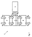
- FIG. 1 shows a schematic sequence of a production line 1 for the production of passenger cars A and B on one and the same production line.
- the reference symbols A and B represent passenger cars of two different model series.
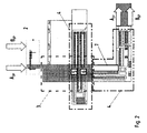
- FIG. 2 goes out a conceivable spatial arrangement of the production line 1.
- the production is characterized in that the cars are prefabricated to a defined state of construction at a remote production location and delivered by means of transport, preferably by train, in a planned transport sequence at an unloading station 2 of the production line 1.
- the passenger cars A in a so-called state of construction 2P so as a painted body A 2P
- the cars B in a so-called construction state 6P so as a body with interior trim B 6P
- the discharge station 2 alternately discharges the transport means which are either loaded with bodies A 2P or bodies B 6P, and sets each chassis A and B 2P 6P on a separate frame, a so-called skid.
- each body A 2P and B 6P attached via an adapter on the frame G. On the adapter is in the FIGS. 1 to 4 not discussed in detail. Its structure and functioning is based on the FIGS. 5 to 9 explained.
- each frame with the adapter and a body A 2P or B 6P is transported via a vertical conveyor on a corresponding conveyor to a decoupling module 3.
- the bodies A 2P are fed into an assembly line 4, which is arranged substantially transversely to the decoupling module 3 and in another plane.
- the bodies A 2P are brought to the construction stage 6P.
- the bodies A are optionally transported on push plates and overhead monorail. Therefore, the bodies A 2P are transferred together with their respective adapter on transfer to the assembly line 4 of its frame on a push plate and lowered by a first vertical conveyor 5 in the other plane.
- the bodies A 6P and B 6P are sequenced, ie transferred in a planned application order in a lead-7.
- the transfer of parked on the frame bodies A 6P and B 6P again takes place together with the adapter to the used in the final assembly 8 monorail systems.
- the bodies A 6P and B 6P are brought into their stage of construction 8P and leave as bodies A 8P and B 8P the production line 1, for which purpose the adapters have to be removed from the respective passenger cars A and B respectively.
- FIG. 3 goes the decoupling module 3 forth.
- the bodies A 2P are obliquely hatched, the bodies A 6P gray and the bodies B 6P filled black.
- the decoupling module 3 comprises an optional memory 9 adapted to receive racks of bodies of any kind (A 2P , A 6P , B 6P ).
- a gas storage 10 for bodies B 6P a gas storage 11 for bodies A 2P and a gas storage 12 for bodies A 6P are provided.
- the designated by reference numeral 13 station is used for sequencing and transfer of the bodies A 6P and B 6P in the delay line 7. D. h., Here the bodies A 6P and B 6P are mixed in the order on a conveyor line 14 in which they to be made in the final assembly 8.
- the bodies stored on their frames G can be translated from any position on two outside rails 15 and 16 to a middle rail 17 and moved back and forth on this.
- the racks G with the bodies can be conveyed directly to the sequencing station 13 or to the vertical conveyor 5. That is, each of the bodies in the random access memory 9 may be accessed as needed to be introduced at any point in the process.
- Parallel behind the rails 15, 16 and 17 of the random memory 9 runs a conveyor line 18 for the transport of adapters equipped with racks G back to the unloading station 2, where they can each be re-equipped with a newly arrived body.
- the gas storage 10 is provided with six memory lanes 19, in which bodies B 6P are stored in succession in the order in which they are to be introduced into the final assembly 8 according to plan.
- the gas storage 11 takes the bodies A 2P on a total of nine memory lanes 19 in the order in which they are to be introduced into the assembly line 4.
- the order of the bodies A 6P in the eight memory lanes 19 of the lane 12 in turn depends on the order in which the bodies in the final assembly 8 are to be mixed with the bodies B 6P .
- the arrows drawn in the memory lanes 19 indicate the intended conveying direction.
- the gas storage 10, 11, 12, the random memory 9 and the sequencing station 13 are connected by transverse conveyor lines 20 with each other.
- the drawn in the conveyor lines 20 arrows show the permissible transport direction.
- a bypass conveyor line 21 is provided on the bodies B 6P can be conveyed directly from the unloading station 2 in the order supplied to the sequencing station 13.
- the two vertical conveyors 5 and 6 are arranged, with which the bodies A 2P from the gas storage 11 in the assembly line 4 and discharged from the assembly line 4 in the gas storage 12 as zugefertigte bodies A 6P again , From the gas storage 12, the bodies A 6P reach the sequencing station 13 according to the arrows shown.
- the sequencing station 13 can be used to assemble exactly the sequence required for the mixed production of the bodies A 6P and B 6P in the final assembly 8 from the incoming circumferences.
- the decoupling module 3 is connected to the flow path 7 via the sequencing station 13.
- the bodies A 6P and B 6P conveyed in the planned application sequence on a conveyor line 22 adjoining the conveyor line 14 are transferred at a transfer station 23 from their respective frame G together with their adapter to a suspension trolley W of an overhead monorail 24.
- a return station 25 is arranged. From the transfer station 23, the currently vacant rack G is transferred to the return station 25. There is a hand in the final assembly 8 empty hanging trolley W, which now only carries the adapter of the meantime put on his built in the final assembly 8 wheels vehicle, the adapter automatically passed to the vacant frame G. This then travels along with the adapter stored thereon on the conveyor line 18 to the unloading station 2. The newly arriving bodies A 2P and B 6P are parked in the unloading station 2 with the interposition of the adapter on the racks G.
- the bodies A and B are thus transported throughout the manufacturing process together with the adapter within the production line 1, promoted and handed over until the vehicle is parked by the trolley W on its wheels.
- the adapter remains on the suspension trolley W until it reaches the return station 25.
- the suspension trolley W is free to take over a body A 6P or B 6P with the respective adapter.
- an adapter 30 is provided which remains over the entire manufacturing process to the point on the bodies A and B, until this be put on their wheels.
- the adapter 30 comprises two mirror-symmetrically aligned adapter halves 30a and 30b. These have on their upper side two mandrels 31a and 32a and 31b and 32b.
- the position of the mandrels 31a, 31b and 32a, 32b depends on the receiving points on the ground system of the passenger car A. It can be provided that the mandrels 31a, 31b and 32a, 32b are formed eccentrically, wherein by turning the mandrels 31 and 32 takes place about its longitudinal axis a locking at the receiving points. This twisting can be done automatically.
- the advantage of this lock is that the body A can be additionally rotated in a suspension trolley W about the vehicle longitudinal axis, without falling out is possible.
- each adapter half 30a, 30b front with two engagement openings 33a, 33b and 34a, 34b and rear with two engagement openings 35a, 35b and 36a, 36b provided.
- the position of these engagement openings depends on the engaging pins of the respective conveyor technology.
- the engagement openings 33a, 33b, 36a and 36b corresponding to the pins 37a, 37b, 38a and 38b of a hanging carriage W, of which only the two gripper arms 39a and 39b are shown, arranged the electric monorail, not shown.
- the engagement openings 34a, 34b, 35a and 35b are positioned corresponding to the pins 40a, 40b, 41a and 41b of a pusher plate S on the underside of the adapter halves 30a and 30b.
- the adapters for the bodies B are identical in the described embodiment with the adapters 30 for the bodies A, since the receiving points on the bodies A and B are identical. However, it is also conceivable that the receiving points of the bodies A differ from those of the body B. In this case, the adapter halves 30a and 30b differ only in that the mandrels are positioned for the receiving points corresponding to the ground system.
- the engagement openings 33, 34, 35 and 36 for the conveyor technology remain in the same position, so that the pins of the conveyor always independent of the respectively received body on the same position. This has the advantage that bodies of different model series, ie can be transported with different receiving points on the ground system on a common production line 1. In addition, by the two front engagement openings 33 and 34 and the two rear engagement openings 35 and 36, the body can be transferred from one to the other conveyor without complex conversion processes or Umgreifprozeduren must be performed.
- the advantageous conversion by the adapter 30 can be summarized using the example of a conversion process of a suspension trolley of a monorail system on a thrust plate as follows:
- the suspension trolley W is lowered in the direction of the arrow Z onto the thrust plate S in such a way that the spigots 40a, 40b, 41a, 41b are in register with the engagement openings 34a, 34b, 35a, 35b.
- the suspension trolley is lowered so far that the pins 37a, 37b, 38a, 38b are no longer in engagement with their corresponding ones Engagement openings 33a, 33b, 36a, 36b are located.
- the thrust plate S can now be moved with the recorded adapter 30 respectively the body A, not shown, according to arrow direction X from the front of the gripping arms 39a, 39b spanned area away.
- the push plate S can be raised in the opposite direction of the arrow Z and the hanging carriage W can be moved away in or against the arrow X direction.
- the adapter 30 and the body of the push plate S on a suspension trolley W or from the frame G on a push plate S and vice versa to pass. Since the adapter 30 always has four free engagement openings, even if it is held by a first conveyor, The body can always be handed over to a second conveyor without the body has to be implemented.
Landscapes
- Engineering & Computer Science (AREA)
- Manufacturing & Machinery (AREA)
- Chemical & Material Sciences (AREA)
- Combustion & Propulsion (AREA)
- Transportation (AREA)
- Mechanical Engineering (AREA)
- Intermediate Stations On Conveyors (AREA)
- Automobile Manufacture Line, Endless Track Vehicle, Trailer (AREA)
- Automatic Assembly (AREA)
Claims (6)
- Ligne de production pour la fabrication de véhicules automobiles, dans laquelle une caisse (A2P, B6P) sur un poste de départ, notamment sur un poste de déchargement (2), est placée sur un premier moyen de transport, en particulier un bâti (G), un adaptateur (30) étant prévu entre la caisse et le moyen de transport, caractérisée en ce que l'adaptateur reste à la fin de la ligne de production sur le dernier moyen de transport libéré, en particulier un chariot suspendu (W), et est transféré, en un poste de retour (25) au niveau duquel se croisent le premier et le dernier moyen de transport, au premier moyen de transport en vue de son retour au poste de départ.
- Ligne de production selon la revendication 1,
caractérisée en ce
qu'entre le premier moyen de transport et le dernier moyen de transport sont prévus d'autres moyens de transport sur lesquels la caisse (A2P, A6P, B6P) est transférée avec l'adaptateur. - Ligne de production selon la revendication 1 ou 2,
caractérisée en ce que
le premier moyen de transport est un bâti (G) qui est ramené sur une voie de transport (18) jusqu'au poste de déchargement (2). - Ligne de production selon la revendication 3,
caractérisée en ce que
la voie de transport (18) s'étend depuis le poste de retour (25) par le biais d'un module de découplage (3) jusqu'au poste de départ, notamment jusqu'au poste de déchargement (2). - Ligne de production selon l'une quelconque des revendications précédentes,
caractérisée en ce que
le dernier moyen de transport est un chariot suspendu (W) qui est transporté par un convoyeur aérien électrique (24). - Ligne de production selon l'une quelconque des revendications précédentes,
caractérisée en ce
qu'un poste de transfert (23) est monté avant le poste de retour (25), au niveau duquel poste de transfert la caisse est transférée du bâti (G) au chariot suspendu (W), le bâti (G) devenu vide étant transporté au poste de retour (25).
Priority Applications (1)
| Application Number | Priority Date | Filing Date | Title |
|---|---|---|---|
| PL09002500T PL2113450T3 (pl) | 2008-04-30 | 2009-02-21 | Linia produkcyjna do produkcji samochodów |
Applications Claiming Priority (1)
| Application Number | Priority Date | Filing Date | Title |
|---|---|---|---|
| DE102008022442A DE102008022442A1 (de) | 2008-04-30 | 2008-04-30 | Fertigungslinie zur Herstellung von Kraftfahrzeugen |
Publications (3)
| Publication Number | Publication Date |
|---|---|
| EP2113450A2 EP2113450A2 (fr) | 2009-11-04 |
| EP2113450A3 EP2113450A3 (fr) | 2010-06-16 |
| EP2113450B1 true EP2113450B1 (fr) | 2012-01-18 |
Family
ID=40456062
Family Applications (1)
| Application Number | Title | Priority Date | Filing Date |
|---|---|---|---|
| EP09002500A Not-in-force EP2113450B1 (fr) | 2008-04-30 | 2009-02-21 | Ligne de production de véhicules automobiles |
Country Status (4)
| Country | Link |
|---|---|
| EP (1) | EP2113450B1 (fr) |
| DE (1) | DE102008022442A1 (fr) |
| PL (1) | PL2113450T3 (fr) |
| RU (1) | RU2489299C2 (fr) |
Families Citing this family (2)
| Publication number | Priority date | Publication date | Assignee | Title |
|---|---|---|---|---|
| DE102009010455A1 (de) | 2009-02-14 | 2010-08-19 | Dr. Ing. H.C. F. Porsche Aktiengesellschaft | Aufnahmevorrichtung für eine Fördereinrichtung |
| CN102941888B (zh) * | 2012-12-04 | 2015-01-14 | 北京汽车研究总院有限公司 | 车身吊具及其转接模块 |
Family Cites Families (8)
| Publication number | Priority date | Publication date | Assignee | Title |
|---|---|---|---|---|
| JPS5923781A (ja) * | 1982-07-29 | 1984-02-07 | Nissan Motor Co Ltd | 搬送装置 |
| DE19641048C2 (de) * | 1996-10-04 | 2000-07-20 | Flaekt Ab | Verfahren zum Ein- und Ausbringen von Werkstücken, insbesondere Fahrzeugkarosserien, Vorrichtung und Anlage zur Oberflächenbehandlung von Werkstücken im Durchlauf |
| EP1293419A3 (fr) * | 2001-09-14 | 2004-04-21 | Nissan Motor Company, Limited | Appareil pour le transport de carrosseries de véhicules |
| JP3983183B2 (ja) * | 2003-02-18 | 2007-09-26 | トヨタ車体株式会社 | 搬送設備 |
| FR2913946B1 (fr) * | 2007-03-20 | 2009-05-08 | Renault Soc Par Actions Simpli | Dispositif de manutention pour soubassement de vehicule automobile |
| DE102007014850B4 (de) * | 2007-03-28 | 2023-05-04 | Bayerische Motoren Werke Aktiengesellschaft | Fertigungsstraße |
| DE202007005034U1 (de) * | 2007-04-04 | 2008-08-21 | Kuka Systems Gmbh | Fördereinrichtung |
| DE202007009334U1 (de) * | 2007-07-03 | 2008-11-13 | Kuka Systems Gmbh | Bauteilträger |
-
2008
- 2008-04-30 DE DE102008022442A patent/DE102008022442A1/de not_active Withdrawn
-
2009
- 2009-02-21 EP EP09002500A patent/EP2113450B1/fr not_active Not-in-force
- 2009-02-21 PL PL09002500T patent/PL2113450T3/pl unknown
- 2009-04-27 RU RU2009115714/11A patent/RU2489299C2/ru active
Also Published As
| Publication number | Publication date |
|---|---|
| PL2113450T3 (pl) | 2012-06-29 |
| RU2009115714A (ru) | 2010-11-10 |
| EP2113450A3 (fr) | 2010-06-16 |
| DE102008022442A1 (de) | 2009-11-05 |
| EP2113450A2 (fr) | 2009-11-04 |
| RU2489299C2 (ru) | 2013-08-10 |
Similar Documents
| Publication | Publication Date | Title |
|---|---|---|
| DE2440682C3 (de) | Umschlagsystem für Container und Paletten | |
| DE3136687C2 (de) | System, Betriebsverfahren und Vorrichtungen zum gleichzeitigen und rangierfreien Umschlag zwischen Schiene und Schiene sowie Strasse und Schiene | |
| EP1995192A2 (fr) | Système de chargement pour bagages d'avion et procédé de tri manuel ou mécanique | |
| EP1539619B1 (fr) | Procede pour charger et decharger | |
| EP3526534B1 (fr) | Appareil pour réguler la température, installation de traitement de surfaces, installation de production et méthode de production | |
| DE102019106033A1 (de) | Regalbediengerät zum Verladen von stapelfähigen Waren und Logistiksystem mit einem solchen Regalbediengerät | |
| EP1362810B1 (fr) | Poste de chargement et déchargement de porteurs de carrosseries de véhicule, de véhicules ou similaires | |
| EP1241118B1 (fr) | Procédé et dispositif de chargement et déchargement de marchandises volumineuses palettisées des véhicules routiers aux rames ferroviaires et inversement | |
| DE3833942A1 (de) | Verfahren und vorrichtung zum automatischen umsetzen von grossen behaeltern, wie containern | |
| DE102014015963B4 (de) | Gerüstwechselsystem, Wechselwagen und Weiche für ein Gerüstwechselsystem und Walzwerk mit einem Walzblock und einem Gerüstwechselsystem | |
| EP2316713B1 (fr) | Chariot de distribution pour le transport et la livraison de composants entre les entreposages intermédiares lors de la production | |
| EP2218633B1 (fr) | Procédé de montage pour véhicules automobiles | |
| EP2113450B1 (fr) | Ligne de production de véhicules automobiles | |
| DE4436901B4 (de) | Fertigungsstraße mit Mitteln zum Schwenken zu bearbeitender Gegenstände | |
| EP1733980B1 (fr) | Dispositif de transport d'au moins une bobine de matériau | |
| EP2113452B1 (fr) | Ligne de fabrication destinée à la production de véhicules automobiles | |
| EP2113451B1 (fr) | Procédé et dispositif destinés à la fabrication de véhicules automobiles | |
| EP0599841B1 (fr) | Procede et dispositif pour le transbordement de conteneurs | |
| DE4414528C2 (de) | Anlage zum Be- und Entladen von Eisenbahnwaggons | |
| DE102010040152A1 (de) | Vorrichtung zum Umsetzen von Ladungsträgern und Beladestation | |
| DE102008036067A1 (de) | Logistiksystem | |
| DE4435056B4 (de) | Verfahren und Vorrichtung zum Lagern von Gegenständen | |
| DE102020213540A1 (de) | Fertigungsanlage zur Serienfertigung von Kraftfahrzeugen und Verfahren zum Fertigen eines Kraftfahrzeugs | |
| DE102008022558B4 (de) | Verfahren zum kontinuierlichen Bearbeiten von Güterwagen | |
| EP3388370B1 (fr) | Utilisation d'un stockage pour les chariots porte-pièces |
Legal Events
| Date | Code | Title | Description |
|---|---|---|---|
| PUAI | Public reference made under article 153(3) epc to a published international application that has entered the european phase |
Free format text: ORIGINAL CODE: 0009012 |
|
| AK | Designated contracting states |
Kind code of ref document: A2 Designated state(s): AT BE BG CH CY CZ DE DK EE ES FI FR GB GR HR HU IE IS IT LI LT LU LV MC MK MT NL NO PL PT RO SE SI SK TR |
|
| AX | Request for extension of the european patent |
Extension state: AL BA RS |
|
| RAP1 | Party data changed (applicant data changed or rights of an application transferred) |
Owner name: DR. ING. H.C. F. PORSCHE AG |
|
| PUAL | Search report despatched |
Free format text: ORIGINAL CODE: 0009013 |
|
| AK | Designated contracting states |
Kind code of ref document: A3 Designated state(s): AT BE BG CH CY CZ DE DK EE ES FI FR GB GR HR HU IE IS IT LI LT LU LV MC MK MT NL NO PL PT RO SE SI SK TR |
|
| AX | Request for extension of the european patent |
Extension state: AL BA RS |
|
| 17P | Request for examination filed |
Effective date: 20101216 |
|
| AKX | Designation fees paid |
Designated state(s): CZ DE FR HU PL SK |
|
| GRAP | Despatch of communication of intention to grant a patent |
Free format text: ORIGINAL CODE: EPIDOSNIGR1 |
|
| GRAS | Grant fee paid |
Free format text: ORIGINAL CODE: EPIDOSNIGR3 |
|
| GRAA | (expected) grant |
Free format text: ORIGINAL CODE: 0009210 |
|
| AK | Designated contracting states |
Kind code of ref document: B1 Designated state(s): CZ DE FR HU PL SK |
|
| REG | Reference to a national code |
Ref country code: DE Ref legal event code: R096 Ref document number: 502009002443 Country of ref document: DE Effective date: 20120315 |
|
| REG | Reference to a national code |
Ref country code: SK Ref legal event code: T3 Ref document number: E 11141 Country of ref document: SK |
|
| REG | Reference to a national code |
Ref country code: PL Ref legal event code: T3 |
|
| PLBE | No opposition filed within time limit |
Free format text: ORIGINAL CODE: 0009261 |
|
| STAA | Information on the status of an ep patent application or granted ep patent |
Free format text: STATUS: NO OPPOSITION FILED WITHIN TIME LIMIT |
|
| 26N | No opposition filed |
Effective date: 20121019 |
|
| REG | Reference to a national code |
Ref country code: DE Ref legal event code: R097 Ref document number: 502009002443 Country of ref document: DE Effective date: 20121019 |
|
| REG | Reference to a national code |
Ref country code: HU Ref legal event code: AG4A Ref document number: E015180 Country of ref document: HU |
|
| REG | Reference to a national code |
Ref country code: FR Ref legal event code: PLFP Year of fee payment: 8 |
|
| REG | Reference to a national code |
Ref country code: FR Ref legal event code: PLFP Year of fee payment: 9 |
|
| REG | Reference to a national code |
Ref country code: FR Ref legal event code: PLFP Year of fee payment: 10 |
|
| PGFP | Annual fee paid to national office [announced via postgrant information from national office to epo] |
Ref country code: FR Payment date: 20210225 Year of fee payment: 13 Ref country code: CZ Payment date: 20210222 Year of fee payment: 13 |
|
| PGFP | Annual fee paid to national office [announced via postgrant information from national office to epo] |
Ref country code: HU Payment date: 20210318 Year of fee payment: 13 Ref country code: PL Payment date: 20210212 Year of fee payment: 13 |
|
| PGFP | Annual fee paid to national office [announced via postgrant information from national office to epo] |
Ref country code: SK Payment date: 20210219 Year of fee payment: 13 |
|
| REG | Reference to a national code |
Ref country code: SK Ref legal event code: MM4A Ref document number: E 11141 Country of ref document: SK Effective date: 20220221 |
|
| PG25 | Lapsed in a contracting state [announced via postgrant information from national office to epo] |
Ref country code: SK Free format text: LAPSE BECAUSE OF NON-PAYMENT OF DUE FEES Effective date: 20220221 Ref country code: CZ Free format text: LAPSE BECAUSE OF NON-PAYMENT OF DUE FEES Effective date: 20220221 |
|
| PG25 | Lapsed in a contracting state [announced via postgrant information from national office to epo] |
Ref country code: HU Free format text: LAPSE BECAUSE OF NON-PAYMENT OF DUE FEES Effective date: 20220222 |
|
| PG25 | Lapsed in a contracting state [announced via postgrant information from national office to epo] |
Ref country code: FR Free format text: LAPSE BECAUSE OF NON-PAYMENT OF DUE FEES Effective date: 20220228 |
|
| PG25 | Lapsed in a contracting state [announced via postgrant information from national office to epo] |
Ref country code: PL Free format text: LAPSE BECAUSE OF NON-PAYMENT OF DUE FEES Effective date: 20220221 |
|
| PGFP | Annual fee paid to national office [announced via postgrant information from national office to epo] |
Ref country code: DE Payment date: 20240129 Year of fee payment: 16 |
|
| REG | Reference to a national code |
Ref country code: DE Ref legal event code: R119 Ref document number: 502009002443 Country of ref document: DE |
|
| PG25 | Lapsed in a contracting state [announced via postgrant information from national office to epo] |
Ref country code: DE Free format text: LAPSE BECAUSE OF NON-PAYMENT OF DUE FEES Effective date: 20250902 |