EP2113616A1 - Système cpad pour réaliser des constructions à ossature préfabriquée toutes fonctions, et procédé correspondant - Google Patents
Système cpad pour réaliser des constructions à ossature préfabriquée toutes fonctions, et procédé correspondant Download PDFInfo
- Publication number
- EP2113616A1 EP2113616A1 EP07710992A EP07710992A EP2113616A1 EP 2113616 A1 EP2113616 A1 EP 2113616A1 EP 07710992 A EP07710992 A EP 07710992A EP 07710992 A EP07710992 A EP 07710992A EP 2113616 A1 EP2113616 A1 EP 2113616A1
- Authority
- EP
- European Patent Office
- Prior art keywords
- layouts
- functional
- prefab
- building
- facilities
- Prior art date
- Legal status (The legal status is an assumption and is not a legal conclusion. Google has not performed a legal analysis and makes no representation as to the accuracy of the status listed.)
- Withdrawn
Links
Images






Classifications
-
- G—PHYSICS
- G06—COMPUTING OR CALCULATING; COUNTING
- G06Q—INFORMATION AND COMMUNICATION TECHNOLOGY [ICT] SPECIALLY ADAPTED FOR ADMINISTRATIVE, COMMERCIAL, FINANCIAL, MANAGERIAL OR SUPERVISORY PURPOSES; SYSTEMS OR METHODS SPECIALLY ADAPTED FOR ADMINISTRATIVE, COMMERCIAL, FINANCIAL, MANAGERIAL OR SUPERVISORY PURPOSES, NOT OTHERWISE PROVIDED FOR
- G06Q10/00—Administration; Management
-
- E—FIXED CONSTRUCTIONS
- E04—BUILDING
- E04B—GENERAL BUILDING CONSTRUCTIONS; WALLS, e.g. PARTITIONS; ROOFS; FLOORS; CEILINGS; INSULATION OR OTHER PROTECTION OF BUILDINGS
- E04B7/00—Roofs; Roof construction with regard to insulation
- E04B7/02—Roofs; Roof construction with regard to insulation with plane sloping surfaces, e.g. saddle roofs
- E04B7/022—Roofs; Roof construction with regard to insulation with plane sloping surfaces, e.g. saddle roofs consisting of a plurality of parallel similar trusses or portal frames
-
- E—FIXED CONSTRUCTIONS
- E04—BUILDING
- E04B—GENERAL BUILDING CONSTRUCTIONS; WALLS, e.g. PARTITIONS; ROOFS; FLOORS; CEILINGS; INSULATION OR OTHER PROTECTION OF BUILDINGS
- E04B7/00—Roofs; Roof construction with regard to insulation
- E04B7/02—Roofs; Roof construction with regard to insulation with plane sloping surfaces, e.g. saddle roofs
- E04B7/06—Constructions of roof intersections or hipped ends
- E04B7/063—Hipped ends
-
- E—FIXED CONSTRUCTIONS
- E04—BUILDING
- E04D—ROOF COVERINGS; SKY-LIGHTS; GUTTERS; ROOF-WORKING TOOLS
- E04D13/00—Special arrangements or devices in connection with roof coverings; Protection against birds; Roof drainage ; Sky-lights
- E04D13/15—Trimming strips; Edge strips; Fascias; Expansion joints for roofs
- E04D13/158—Trimming strips; Edge strips; Fascias; Expansion joints for roofs covering the overhang at the eave side, e.g. soffits, or the verge of saddle roofs
-
- G—PHYSICS
- G06—COMPUTING OR CALCULATING; COUNTING
- G06F—ELECTRIC DIGITAL DATA PROCESSING
- G06F30/00—Computer-aided design [CAD]
- G06F30/10—Geometric CAD
- G06F30/13—Architectural design, e.g. computer-aided architectural design [CAAD] related to design of buildings, bridges, landscapes, production plants or roads
-
- B—PERFORMING OPERATIONS; TRANSPORTING
- B28—WORKING CEMENT, CLAY, OR STONE
- B28B—SHAPING CLAY OR OTHER CERAMIC COMPOSITIONS; SHAPING SLAG; SHAPING MIXTURES CONTAINING CEMENTITIOUS MATERIAL, e.g. PLASTER
- B28B15/00—General arrangement or layout of plant ; Industrial outlines or plant installations
-
- G—PHYSICS
- G06—COMPUTING OR CALCULATING; COUNTING
- G06F—ELECTRIC DIGITAL DATA PROCESSING
- G06F2111/00—Details relating to CAD techniques
- G06F2111/02—CAD in a network environment, e.g. collaborative CAD or distributed simulation
-
- G—PHYSICS
- G06—COMPUTING OR CALCULATING; COUNTING
- G06F—ELECTRIC DIGITAL DATA PROCESSING
- G06F2111/00—Details relating to CAD techniques
- G06F2111/20—Configuration CAD, e.g. designing by assembling or positioning modules selected from libraries of predesigned modules
Definitions
- the present invention generally relates to fabrication systems and structures of prefab buildings.
- it relates to computer controlled prefab system for all-functional prefab framed buildings, all-functional prefab framed building structures fabricated by utilizing the mentioned system and a quick assembling method thereof.
- the modular building systems are of limited building functions, difficult to be transported to distant locations, and compromised by the lack of individuality of buildings, although they are at higher degree of factory integration and in need of less on-site construction work.
- some prefab building systems are disclosed in U.S. Pat. No. US6,951,079 ; US6,651,393 ; US4,378,664 ; US6,088,970 ; US6,253,521 ; US6,959,514 and Chinese Patent Application 200410022604.2 ; 02256168.4 ; 03236966.2 ; 94103337.6 ; 00201861.6 .
- CPAD computerized prefab architect design
- a computer controlled fabrication system for all-functional prefab framed buildings that comprises:
- the computer controlled fabrication system for all-functional prefab framed buildings also comprises an interactive selection system (ISS), comprising:
- an all-functional prefab framed building structure fabricated by the above system comprising:
- This invention may be utilized to realize the customized building designs, fabrication, constructions and business operations and to form whole sets of customized all-functional framed structures, building elements and assemblies, as well as various well-assorted functional connectors.
- Most of the mentioned building elements and assemblies are panel like components and some others are structural components such as polygonal frames and trusses, comprising wall panels, flooring panels, ceiling panels, beams, joists, ring beams, lattice beams, roof trusses and roof panels, etc.
- some components may be pre-assembled with one or more facilities, such as cold and hot water supply facilities and fittings, gas facilities and fittings, drainage and sewage facilities and fittings, power system and fittings, communication system and fittings, security system and fittings, multimedia system and fittings, windows and doors, etc.
- the mentioned building elements and assemblies are container transportable.
- a usable building is established by assembling the mentioned prefab building elements, assemblies and attachments using general mechanical fasteners in a mechanical way, instead of large amount of traditional construction work.
- Such a building system compared with the traditional ones, requires more precisely fabricated building elements and/or assemblies, including independent and dependent elements and/or assemblies, as well as parts, hence, for customer-designed buildings, it must be supported by a computer controlled fabrication and on-site quick assemble system.
- This invention may be utilized to realize the scale production of individualized buildings with precision, efficiency and speed, by way of transforming a large amount of traditional construction works into a process in factory environment and a mechanical assembly method on building site, so that construction waste, labors, building time and consumed energy may be significantly reduced.
- three dimensional frame-structured buildings are properly divided into two dimensional constructional elements and assemblies with smaller thickness, so that whole sets of container transportable all-functional frame-structure constructional elements and assemblies and various well-assorted functional connectors can be precisely customized at factories as required.
- Most of the mentioned elements and assemblies are panel like components and some others are structural components such as polygonal frames and trusses.
- the mentioned elements and assemblies may comprise wall panels, flooring panels, ceiling panels, beams, joists, ring beams, lattice beams, roof trusses and roof panels, etc., wherein some components may be pre-attached with one or more facilities, such as cold/hot water supply facilities and fittings, gas facilities and fittings, drainage and sewage facilities and fittings, power system and fittings, communication system and fittings, security system and fittings, multimedia system and fittings, and windows and doors, etc.
- facilities such as cold/hot water supply facilities and fittings, gas facilities and fittings, drainage and sewage facilities and fittings, power system and fittings, communication system and fittings, security system and fittings, multimedia system and fittings, and windows and doors, etc.
- the building elements, assemblies and parts of this framed building system are more precise compared with the traditional ones, the traditional on-site construction work can be significantly reduced, and the prefab building elements, assemblies and functional connectors can be mechanically assembled into an usable building by utilizing general mechanical fasteners and auxiliary materials.
- This building system is adaptable to houses, apartments and buildings for other purposes.
- the mentioned computer controlled fabrication system for all-functional prefab framed buildings comprises: an interactive selection system (ISS), a computerized prefab architect design (CPAD) system, an intelligent manufacture management system and manufacture dispatch system (IMMS & MDS), and a product service system (PSS).
- ISS interactive selection system
- CPAD computerized prefab architect design
- IMMS & MDS intelligent manufacture management system and manufacture dispatch system
- PSS product service system
- the mentioned computer controlled system is built on an ERP (Enterprise Resource Project) platform, wherein individualized sales service to end users is facilitated for business cooperative partners of manufacturers by ISS that takes a business-to-business model when they sell constructional products.
- ERP Enterprise Resource Project
- the business cooperative partners only need to provide to the manufactures data required for building design such as floor plan, elevation plan, section plan and other technical specification for acknowledgement in both parties, and the CPAD performs custom design including strength calculation on the building according to the local construction code of the business cooperative partner to generate electronic files for fabrication such as JIT logistics, container loading plan, bill of materials, electronic guide display files including instruction documents for fabrication and container loading, and CAM files, etc.
- ISS When the business cooperative partner sells an existing building design product, he will use ISS to facilitate marketing by allowing an end user to have various individual selections of interior functional structures and interior and exterior finishing of the selected building, such as exterior wall finishing, kitchen and bathroom fittings and appliances, and soft decorations, etc., via ISS and the selection results are transmitted via internet to the manufacturer for individualized production.
- IMMS & MDS precise building elements and assemblies such as profiled framing materials and various kinds of boards for panel like components are processed by computer controlled equipment that utilizes the transmitted CAM files via intranet, various attached functional facilities such as water, electricity, communication, channels, wiring, and communication cabling, etc.
- the building elements and assemblies including doors and windows are assembled on the production lines and loaded into containers for transportation for production of all-functional and all assembled constructional elements and components.
- the whole set of products may be mechanically assembled into a building by utilizing a specially designed crane or other general cranes to quickly complete construction.
- Technical supports may be available via the product service system (PSS) that may also facilitate after-sale services.
- PSS product service system
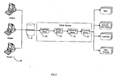
- FIG 3 illustrates a schematic apparatus view of the computerized prefab architect design (CPAD) system of this invention.
- CPAD computerized prefab architect design
- this CPAD system is a network-based CAD cooperating design system, comprising a CAD software based on Intranet and an external database 31 independent of the CAD software.
- data is synchronized, whenever there is a change in the assembly drawing, the system may make corresponding modifications based on the change and make accurate and quick modification to the whole product.
- there is a configuration option selected or disabled there is an update of the part vault of CAD system without a need of rearrangement of parts in the CAD drawing, thus compatibility is automatically achieved and each part is assigned to an exclusively specified identification mark in all drawings, as a result, checking time is reduced.
- the mentioned data comprising floor plans, layouts of plumbing system, layouts of electricity wiring, layouts of electric appliances and fittings, layouts of sanitary appliances and fixtures, layouts of air conditioning system, and parameters of structural strength, etc.
- the mentioned data is input into the CPAD system and integrated into assembly drawings by the integrating device 32.
- the mentioned assemblies and layouts of wall panels, flooring/ceiling panels, roof panels and layouts of roof trusses, as well as the segments and layouts of plumbing, wiring and cabling and jointers are formed by the dividing device 33.
- stencils provided with polygons are generated by the generating device 34.
- the mentioned stencils are utilized by the CPAD system to generate frames, functional boards to be mounted onto the frames and various attached functional facilitates.
- the mentioned functional boards may comprise, for example, structural boards, covering boards, waterproofing layer, thermal insulation layer and interior and exterior finishing layers.
- the mentioned attached functional facilities may comprise, for example, windows, doors, plumbing, wiring and sockets, etc.
- the system extracts data on required materials from the database. Finally, the data are output by the outputting device 35, including detailed bills of materials, electronic guide displays, CAM files, loading plans and assembly drawings for on-site work, etc.
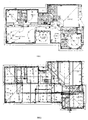
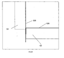
- floor plans as illustrated in FIG 1 are transformed by designers 30 into the system-readable CAD format as illustrated in FIG. 2 , and fabrication and assembly drawings for production lines to fabricate building elements and assemblies are automatically generated.
- the said drawings may comprise those for the fabrication and assembly of sandwiched (multilayered) components such as wall panels, ceiling panels, roof panels, flooring panels and ring beams, etc., and roof trusses and joists, etc.
- layouts of plumbing, electricity wiring, gas facilities and fittings, communication cabling, security system and multimedia system are automatically integrated into the said fabrication and assembly drawings for the building elements and assemblies in accordance with their functions in the building, and drawings for material cuttings are generated accordingly for the fabrication process.
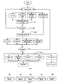
- FIG. 4 illustrates a schematic view of a flow chart of the computerized prefab architect design (CPAD) system.
- CPAD computerized prefab architect design
- the system integrates customer acknowledged building design elements including floor plans, plumbing layouts, electricity wiring layouts , layouts of electric appliances and fittings, layouts of sanitary appliances and fixtures, layouts of air conditioning system and structure/strength parameters into an assembly drawing.
- the system forms segments and layouts of wall panels, floor/ceiling panels and roof panels, layouts of roof trusses, and segments and layouts of plumbing, wiring and jointers in accordance with a segmentation rule for buildings comprising a local building specification, segmentation based on a loading size of a shipping container, strength and structural requirements of buildings, requirements for convenient on-site work and flexible assembly lines at factories.
- the system generates a polygon stencil for components of the prefab architect based on said segments and layouts, said stencil including building frames, functional boards to be mounted onto the frames and functional accessories and appliances and the stencils includes for example stencils of frames, plumbing layouts, electricity wiring layouts, gas facilities arrangements, communication cabling, security and multimedia layouts and appliances arrangements.
- the system forms data including a list of materials, an electronic guide display, CAM files, container loading plans and assembly drawings for on-site work in accordance with requirements for the fabrication in said stencils.
- FIG 5 illustrates a schematic view of the intelligent manufacture management system and manufacture dispatch system (IMMS & MDS) of this invention.
- IMMS & MDS precise fabrication, correct loading and transportation, and quick assembly on building site of a customer selected building is guaranteed by the IMMS & MDS.
- the results of detailed design for fabrication are imported by IMMS & MDS for making production plan and the replacing device 51 replaces default specifications with customer selected individualized specifications; and then the planning device 52 generates dada including task lists for assembly and pre-process, a list of materials and a dispatch order to work stations, etc.
- the pre-processing device 53 CAM pre-processes precise parts and components utilizing the CAM files that are transmitted through Intranet to the specified equipment, and/or functional accessories of attached facilities in accordance with the electronic guide display.
- the dispatching apparatus 54 materials, pre-processed parts and components and functional accessories of attached facilities are precisely dispatched to corresponding work stations in the pre-processing and assembly lines in accordance with the bills of materials output from the CPAD that are linked with the warehouses and materials supply, and the electronic guide display for the pre-processing is transmitted to the work stations wherein instructions are given to guide operations such as cutting of pipes, wires and boards, etc.; and by the assembling device 55, the electronic guide display for assembly is transmitted to the work stations wherein instructions are given to guide operations to complete the compound building elements, assemblies and functional accessories, including making up frames, mounting boards on the frames, assembling various functional accessories and attachments such as windows and doors, pipes and wires, etc., and to load them into containers in accordance with the loading plan generated by the mentioned CPAD system.
- Connecting points and locating points of the components are precisely designed by the CPAD system and fabricated by digital controlled equipment so that precise location and assembly on building site are guaranteed. All finished and semifinished building elements, assemblies and functional accessories generated in the pre-processing and assembling process are controlled and checked by bar codes so that the correctness of manufacturing is assured. This process may accept the requirements for the products specified by the ISS and CPAD system.
- FIG. 6 illustrates a schematic view of a flow chart of the intelligent manufacture management system and manufacture dispatch system (IMMS & MDS) of FIG. 5 .
- IMMS & MDS intelligent manufacture management system and manufacture dispatch system
- Step 61 default specifications are replaced with customer selected individualized specifications.
- Step 62 dada including task lists for assembly and pre-process, a list of materials and a dispatch order to work stations is generated.
- Step 63 precise parts and components are CAM pre-processed based on said CAM files, and/or attached facilities of said functional accessories are pre-processed based on said electronic guide display.
- materials, pre-processed parts and components and the attached facilities of said functional accessories are dispatched to corresponding work stations in accordance with said list of materials.
- said polygon stencil is assembled in accordance with said electronic guide display into all-functional prefab framed building components suitable for container loading.
- containers are loaded in accordance with the loading plans generated by the CPAD system.
- FIG 7 illustrates a schematic view of a flow chart of the inter-active selection system of this invention.
- ISS is also an effective system for sales management and marketing and uses a B-B electronic business model integrated on a ERP platform.
- end users may be allowed to select their preferred building types and corresponding configuration selection modules demonstrated on the ISS platform via logging in the website of a manufacturer's business cooperative partner.
- There may be displayed in the ISS all the building types in which detailed designs for fabrication have been completed, including their floor plans, brief descriptions of the buildings and standard specifications including exterior and interior finishing and various fixtures and decorations.
- ISS there may also be displayed in the ISS a wide range of options for a certain building and end users are allowed to select what they prefer, such as materials and colors of windows and doors, of exterior and interior finishing and of cabinets and robes, kitchen and bathroom fixtures and decorations, security systems and multimedia systems, etc.
- quotations may be offered and orders may be placed.
- quotations are generated for end users once certain buildings and their configurations are selected.
- orders after acknowledgement of the user may be placed through ISS to a business cooperative partner's management platform.
- inquiry form may be transmitted through ISS from the business cooperative partner to the manufacturer after acknowledgement thereof.
- the inquiry form is transmitted to relevant operational flows via an ERP platform, and may be judged at Step S76 whether or not the requirements of the inquiry can be met by utilizing corresponding data of the logistic module, the producing module, the trade module and the financial module, etc. If it is "Yes” at Step S76, an official order may be generated and automatically introduced to the IMMS & MDS to guide manufacture. If it is "No” at Step S76, it may return to Step S73 wherein the business cooperative partner has to have the order to be re-acknowledaged by the end user.
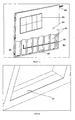
- FIG 8 illustrates the exterior side of a wall panel of a house of this invention, wherein A1 is a structural frame, A2 is a structural board, A3 is an insulation board, A4 is a layer of waterproofing house wrap or reflective film, A5 is a cladding board, A6 is a window and window casing, A7 is a communication socket, A8 is a prefixed bracket for fixing a water pipe, A9 is a junction box for connecting wires on exterior walls, A10 are the main wires which at one end are connected to the junction box and at the other end has a connecting terminal, A11 is a wire clip, A12 is a water pipe, and A13 is a connector for assembly on building site.
- A1 is a structural frame
- A2 is a structural board
- A3 is an insulation board
- A4 is a layer of waterproofing house wrap or reflective film
- A5 is a cladding board
- A6 is a window and window casing
- A7 is a communication socket
- A8
- A1-A12 are parts to satisfy the structural and functional requirements of the building and A13 is to facilitate the quick assembly on building site and has a function of structural connection. It may be allowed to add or remove functions of a wall panel in accordance with the customer's requirements or the applicable building codes.
- FIG 9-a illustrates the interior side of a wall panel of a house of this invention, wherein B1 may be a plaster board of which the surface is finished with decoration, or a fiber cement board when waterproofing is required, B2 is a structural frame, B3 are electricity wires, having a power connecting terminal at one end and at the other end being connected to an in-the-wall junction box, B4 may be a plug seat connected to the electricity wires, B5 is a water pipe pre-fixed in the frame at the factory, B6 is a waterproofing layer that may be ceramic tiles or other waterproofing materials as required by the customer or the applicable building codes, B7 is a hole for assembly on building site as illustrated in FIG. 9-b , B8 is a connector for assembly on building site. B1-B6 are parts to satisfy the structural and functional requirements of the building and B7-B8 are to facilitate the quick assembly on building site and has a function of structural connection.
- B1-B6 are parts to satisfy the structural and functional requirements of the building and B7-B8
- FIG 10 illustrates a ceiling frame of a house of this invention, wherein C1 are electricity wires pre-connected to an in-the-ceiling junction box at factory, C2 is a structural frame of the ceiling, C3 is the in-the-ceiling junction box pre-fixed to the frame at factory, and C4 is a connector for assembly on building site.
- C1-C3 are parts to satisfy the structural and functional requirements of the building and C4 is to facilitate the quick assembly on building site and has a function of structural connection. It may be allowed to add or remove functions of a prefab ceiling frame in accordance with the customer's requirements or the applicable building codes.
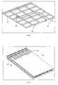
- FIG 11 illustrates a floor panel of a house of this invention, wherein D1 is a floor joist, D2 is a structural covering layer of the flooring, D3 is a connection plate for assembly, and D4 is a steel bar for assembly.
- D1-D2 are parts to satisfy the structural and functional requirements of the building and D3-D4 are to facilitate the quick assembly on building site and has a function of structural connection. It may be allowed to add or remove functions of a floor panel in accordance with the customer's requirements or the applicable building codes.
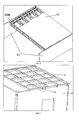
- FIG 12 illustrates a roof panel of a house of this invention, wherein E1 is a structural frame, E2 may be a layer of colorbond roof tile or other types of tiles, or may be a layer of structural board plus various types of tiles.
- FIG 13 illustrates a roof truss of a house of this invention, wherein F1 is a structural frame, F2 is a locating connector for truss assembly, and F3 is a locating clip for roof panel assembly.
- the mentioned mechanical method to quickly assembly the mentioned all-functional prefab framed building structure of this invention may comprise the following locating and connecting methods and steps:
- FIG. 14-a illustrates connection points of a wall panel and foundation slab, wherein G1 is a locator for the erection of a wall panel, G2 is a connector of a wall panel and foundation slab, G3 is a wall panel; as shown in FIG. 14-b , G3 is a wall panel, G22 is a locating bolt anchored on the foundation slab, G24 is a washer and G23 is a nut for assembly.
- FIG. 15-a illustrates connection points of three wall panels, wherein G1 is a locator for the erection of a wall panel, G3 is a wall panel, G33 are connecting fasteners of wall panels; and a detailed view of G33 is shown in FIG. 15-b , wherein G3 is a wall panel, G331 is a wall connector, G332 is a washer and G333is a connecting bolt.
- FIG. 16 illustrates assembly points of a floor panel and a wall panel, wherein H1 is a floor panel, G3 is a wall panel, and G336 is a locating clip-on connector that is fixed on the wall panel for the connection of the wall panel and the floor panel.
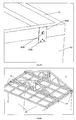
- FIG. 17 illustrates assembly points of a ceiling frame and a wall panel, wherein G3 is a wall panel, I1 is a ceiling frame, and I13 is a locating clip-on connector that is pre-fixed on the ceiling frame.
- FIG. 18 illustrates a detailed view of I13, wherein G3 is a wall panel, I1 is a ceiling component, 1131 is a locating connector pre-fixed on the ceiling frame, I132 is a connecting bolt, and 1133 is a self-tapping screw.
- FIG. 19 illustrates connection points of a roof truss, a ceiling component and a wall panel, wherein J1 is a roof truss, I1 is a ceiling component, G3 is a wall panel, and J14 is a connector of roof truss, wall panel and ceiling component.
- FIG. 20 illustrates a detailed view of J 14, wherein I1 is a ceiling component, J1 is a roof truss, J14 is a connector, and J144 is a self-tapping screw.
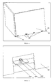
- FIG. 21 illustrates 90-degree-connection points of roof trusses, wherein J1 is a roof truss, J2 is a 90-degree locating device of roof truss, and J3 is a locator for roof panel assembly.
- FIG. 22 illustrates a detail view of J2, wherein J1 is a roof truss, J2 is a 90-degree locating device of roof truss, and J23 is a locating dowel.
- FIG. 23 illustrates other-angel-connection points of roof trusses, wherein J1 is a roof truss, J5 is an arbitrary-angel locating device of roof truss.
- FIG 24 illustrates a detailed view of J5, wherein J1 is a roof truss, J2 is a 90-degree locating device of roof truss, J5 is an arbitrary-angel locating device of roof truss, and J52 is a locating dowel.
- FIG. 25 illustrates assembly points of a roof panel and a roof truss, wherein J1 is a roof truss, K1 is a roof frame, and J3 is a locator for roof panel assembly pre-fixed on the roof truss.
- the roof panel may be fixed on the roof trusses by fasteners after being properly located.
- FIG. 26 illustrates assembly points of a gutter and eaves, wherein I1 is a ceiling component, G3 is a wall panel, L1 is a connector of eaves, L111 is a gutter, L112 is a clip-on hanger of eaves boards, L113 is a transverse eaves board, L114 is a vertical eaves board, and L115 is eaves molding for the transverse eaves board.
- FIG. 27 illustrates a schematic view of a whole assembled house of this invention, wherein G3 is a wall panel, I1 is a ceiling component, J1 is a roof truss, K1 is a roof panel, G33 is a connecting points of wall panels, J14 is a connecting point of roof truss, wall panel and ceiling component, I13 is a locating connecting point of the ceiling component and the wall panel, J2 or J5 is a locating connecting points of roof trusses, J3 is a locating point on a roof truss for roof panel assembly, G2 is a locating connecting of a wall panel and foundation slab, G1 is a locating point for the erection of a wall panel, and L1 is a connector of eaves.
- FIG. 28 illustrates a detailed decorating method for wall panel connection, wherein G3 is a wall panel, and G30 may be the finishing layer of a prefab wall panel, such as a layer of wall paper.
- the quick method to mechanically assemble a prefab building of this invention comprises the following steps:
Landscapes
- Engineering & Computer Science (AREA)
- Physics & Mathematics (AREA)
- Architecture (AREA)
- Civil Engineering (AREA)
- Structural Engineering (AREA)
- Geometry (AREA)
- General Physics & Mathematics (AREA)
- Theoretical Computer Science (AREA)
- Electromagnetism (AREA)
- Computer Hardware Design (AREA)
- Business, Economics & Management (AREA)
- Pure & Applied Mathematics (AREA)
- Entrepreneurship & Innovation (AREA)
- Evolutionary Computation (AREA)
- General Engineering & Computer Science (AREA)
- Mathematical Analysis (AREA)
- Computational Mathematics (AREA)
- Economics (AREA)
- Mathematical Optimization (AREA)
- Human Resources & Organizations (AREA)
- Marketing (AREA)
- Operations Research (AREA)
- Quality & Reliability (AREA)
- Strategic Management (AREA)
- Tourism & Hospitality (AREA)
- General Business, Economics & Management (AREA)
- Management, Administration, Business Operations System, And Electronic Commerce (AREA)
Applications Claiming Priority (1)
| Application Number | Priority Date | Filing Date | Title |
|---|---|---|---|
| PCT/CN2007/000574 WO2008043220A1 (fr) | 2007-02-15 | 2007-02-15 | Système cpad pour réaliser des constructions à ossature préfabriquée toutes fonctions, et procédé correspondant |
Publications (2)
| Publication Number | Publication Date |
|---|---|
| EP2113616A1 true EP2113616A1 (fr) | 2009-11-04 |
| EP2113616A4 EP2113616A4 (fr) | 2015-01-14 |
Family
ID=39282395
Family Applications (1)
| Application Number | Title | Priority Date | Filing Date |
|---|---|---|---|
| EP07710992.4A Withdrawn EP2113616A4 (fr) | 2007-02-15 | 2007-02-15 | Système cpad pour réaliser des constructions à ossature préfabriquée toutes fonctions, et procédé correspondant |
Country Status (4)
| Country | Link |
|---|---|
| US (1) | US20100024318A1 (fr) |
| EP (1) | EP2113616A4 (fr) |
| CN (1) | CN101432489B (fr) |
| WO (1) | WO2008043220A1 (fr) |
Cited By (5)
| Publication number | Priority date | Publication date | Assignee | Title |
|---|---|---|---|---|
| EP2936355A4 (fr) * | 2012-12-19 | 2016-09-07 | Patco Llc | Procédé et système d'utilisation d'éléments structuraux normalisés |
| EP3101193A3 (fr) * | 2015-06-02 | 2017-03-08 | Illinois Tool Works Inc. | Treillis pour une utilisation dans la construction de bâtiments et procédés d'installation associés |
| US9644370B2 (en) | 2014-11-26 | 2017-05-09 | Illinois Tool Works Inc. | Trusses for use in building construction and methods of installing same |
| WO2018165654A1 (fr) | 2017-03-10 | 2018-09-13 | Patco Llc | Plans intelligents |
| CN110952811A (zh) * | 2019-10-24 | 2020-04-03 | 中天西北建设投资集团有限公司 | 一种基于bim的装配式机房深化设计流程及其施工方法 |
Families Citing this family (43)
| Publication number | Priority date | Publication date | Assignee | Title |
|---|---|---|---|---|
| WO2008069764A1 (fr) * | 2006-12-08 | 2008-06-12 | Axis Ip Holding Pte Ltd | Système de construction industrialisé, et procédé associé |
| US20100235206A1 (en) * | 2008-11-14 | 2010-09-16 | Project Frog, Inc. | Methods and Systems for Modular Buildings |
| GB2492347A (en) * | 2011-06-28 | 2013-01-02 | Nicholas Timothy Showan | Building method, cutting apparatus and liquid-laden foam insulator |
| US9305136B2 (en) * | 2012-08-02 | 2016-04-05 | Honeywell International Inc. | Determining a layout and wiring estimation for a heating, ventilation, and air conditioning system of a building |
| DE102014102651B4 (de) * | 2013-03-15 | 2020-12-17 | Taiwan Semiconductor Manufacturing Company, Ltd. | Lithographiesystem mit eingebettetem Reinigungsmodul und Lithographie-Belichtungsverfahren |
| JP5505848B1 (ja) * | 2013-12-02 | 2014-05-28 | 株式会社サイバーノイズ | 画像処理装置、画像処理方法及びプログラム |
| JP5610327B1 (ja) | 2014-03-18 | 2014-10-22 | 株式会社Live2D | 画像処理装置、画像処理方法及びプログラム |
| CN105279292B (zh) * | 2014-06-30 | 2019-07-05 | 上海神机软件有限公司 | 建设工程模板图纸输出系统及方法、排模系统及方法 |
| CN104200026B (zh) * | 2014-09-01 | 2017-05-03 | 深圳汇林达科技有限公司 | 三维空间软件的配模方法及系统 |
| EP3449064A4 (fr) * | 2016-04-29 | 2019-12-11 | Rbon Holdings Pty Ltd | Structure de poutre modulaire et structure de base modulaire |
| US10740502B2 (en) * | 2017-02-22 | 2020-08-11 | Middle Chart, LLC | Method and apparatus for position based query with augmented reality headgear |
| US10740503B1 (en) | 2019-01-17 | 2020-08-11 | Middle Chart, LLC | Spatial self-verifying array of nodes |
| US12086507B2 (en) | 2017-02-22 | 2024-09-10 | Middle Chart, LLC | Method and apparatus for construction and operation of connected infrastructure |
| US12400048B2 (en) | 2020-01-28 | 2025-08-26 | Middle Chart, LLC | Methods and apparatus for two dimensional location based digital content |
| US11625510B2 (en) | 2017-02-22 | 2023-04-11 | Middle Chart, LLC | Method and apparatus for presentation of digital content |
| US11900023B2 (en) | 2017-02-22 | 2024-02-13 | Middle Chart, LLC | Agent supportable device for pointing towards an item of interest |
| US11468209B2 (en) | 2017-02-22 | 2022-10-11 | Middle Chart, LLC | Method and apparatus for display of digital content associated with a location in a wireless communications area |
| US12475273B2 (en) | 2017-02-22 | 2025-11-18 | Middle Chart, LLC | Agent supportable device for communicating in a direction of interest |
| US11900021B2 (en) | 2017-02-22 | 2024-02-13 | Middle Chart, LLC | Provision of digital content via a wearable eye covering |
| CN109175910A (zh) * | 2018-10-17 | 2019-01-11 | 湖北公惠网络科技有限公司 | 一种型材产品的制造方法 |
| EP3904621A4 (fr) * | 2018-12-28 | 2022-02-16 | Mitsubishi Chemical Holdings Corporation | Dispositif de traitement d'agencement de matériau de construction, procédé d'agencement de matériau de construction et programme |
| CN110439290A (zh) * | 2019-07-10 | 2019-11-12 | 中国十七冶集团有限公司 | 一种装配式混凝土结构施工方法 |
| US20210110078A1 (en) * | 2019-10-09 | 2021-04-15 | Consulting Engineers, Corp. | Method and system for determining the panelization of a wall |
| US11443078B2 (en) * | 2019-11-07 | 2022-09-13 | Consulting Engineers, Corp. | Method and system for identifying conflicts within floor joists of a structure |
| US11663376B2 (en) * | 2019-11-07 | 2023-05-30 | Consulting Engineers, Corp. | Method and system for identifying external conflicts with a floor joist assembly |
| US11651116B2 (en) * | 2019-11-07 | 2023-05-16 | Consulting Engineers, Corp. | Method and system for identifying external conflicts with a wall panel assembly |
| US11520950B2 (en) * | 2019-11-07 | 2022-12-06 | Consulting Engineers, Corp. | Method and system for identifying conflicts in a roof truss to roof truss horizontal interface |
| US11574085B2 (en) * | 2019-11-07 | 2023-02-07 | Consulting Engineers, Corp. | Method and system for identifying conflicts in a floor joist and wall panel vertical interface |
| US11526634B2 (en) * | 2019-11-07 | 2022-12-13 | Consulting Engineers, Corp. | Method and system for identifying conflicts in a wall panel to wall panel horizontal interface |
| US11113310B2 (en) * | 2019-11-07 | 2021-09-07 | Consulting Engineers, Corp. | Method and system for identifying issues and conflicts with building construction |
| US11599686B2 (en) * | 2019-11-07 | 2023-03-07 | Consulting Engineers, Corp. | Method and system for identifying conflicts in a wall and foundation interface |
| US11610029B2 (en) * | 2019-11-07 | 2023-03-21 | Consulting Engineers, Corp. | Method and system for identifying conflicts within roof truss of a structure |
| US11657191B2 (en) * | 2019-11-07 | 2023-05-23 | Consulting Engineers, Corp. | Method and system for identifying external conflicts with a roof truss assembly |
| CN111101706B (zh) * | 2019-12-31 | 2020-10-02 | 山东泰安建筑工程集团有限公司 | 一种模块化装配式钢结构房屋的施工方法 |
| US12067521B2 (en) * | 2020-01-14 | 2024-08-20 | Consulting Engineers, Corp. | Method and system for optimizing shipping methodology for cold formed steel studs |
| US11640486B2 (en) | 2021-03-01 | 2023-05-02 | Middle Chart, LLC | Architectural drawing based exchange of geospatial related digital content |
| US20210383033A1 (en) * | 2020-06-09 | 2021-12-09 | Plant Prefab, Inc. | Structural construction system employing architectural modeling |
| CA3207130A1 (fr) | 2020-12-31 | 2022-07-07 | Mitek Holdings, Inc. | Modules de construction a assemblage rapide et procedes d'utilisation |
| US20240183156A1 (en) * | 2021-04-08 | 2024-06-06 | Lionhead Real Estate Designs, Inc. | Systems and methods of construction |
| CN113255033B (zh) * | 2021-05-11 | 2022-04-05 | 上海慧之建建设顾问有限公司 | 基于bim技术的建筑工程监理智能一体化云平台及监理方法 |
| CN115129958B (zh) * | 2022-08-17 | 2023-04-14 | 北京市政路桥股份有限公司 | 一种基于bim技术的预制梁可视化排产方法 |
| CN115807548A (zh) * | 2022-12-28 | 2023-03-17 | 怒江州新基建有限公司 | 一种装配式住宅工程建筑节能施工工法 |
| IT202300008055A1 (it) * | 2023-04-26 | 2024-10-26 | Tecma Solutions S P A | Metodo per progettare un edificio |
Family Cites Families (16)
| Publication number | Priority date | Publication date | Assignee | Title |
|---|---|---|---|---|
| US2256168A (en) | 1937-09-29 | 1941-09-16 | Baker Perkins Co Inc | Conveyer of the endless band type |
| FR1318681A (fr) | 1962-01-08 | 1963-02-22 | Bresson Faille Marchand Ets | Disjoncteur bipolaire |
| PH13116A (en) | 1979-08-06 | 1979-11-29 | Pilar Dev Corp | An improve system for constructing a building |
| CA2112186A1 (fr) * | 1992-12-24 | 1994-06-25 | Barrie Albert Macdonald | Methode de construction de batiment |
| JP3810850B2 (ja) * | 1996-03-25 | 2006-08-16 | ミサワホーム株式会社 | ユニット式建物設計用cadの付属部品入力システム |
| DE19637379C2 (de) * | 1996-09-13 | 1999-06-10 | Buck Chem Tech Werke | Verfahren zum Herstellen von doppelwandigen Wandelementen, dazu verwendete Anlage sowie danach hergestelltes Wandelemente |
| US6959514B1 (en) | 1997-01-22 | 2005-11-01 | Pdg Domus Corporation | Molded wall panel and house construction |
| NZ332445A (en) * | 1998-10-21 | 2001-04-27 | Scottsdale Building Systems Lt | Steel-framed building construction with pre-assembled frames for walls, ceilings, roof and roof supports |
| US6088970A (en) * | 1998-10-21 | 2000-07-18 | Doran; Rodney Garnet | Light building assembly system |
| JP2001076018A (ja) * | 1999-09-01 | 2001-03-23 | Misawa Homes Co Ltd | プレハブ式建物の図面作成用cadシステム |
| US6438903B1 (en) | 2000-01-27 | 2002-08-27 | Fairfax Express Corporation | System and Method of Panelized Construction |
| US7164883B2 (en) * | 2001-02-14 | 2007-01-16 | Motorola. Inc. | Method and system for modeling and managing terrain, buildings, and infrastructure |
| US6651393B2 (en) * | 2001-05-15 | 2003-11-25 | Lorwood Properties, Inc. | Construction system for manufactured housing units |
| US7065476B2 (en) * | 2002-04-22 | 2006-06-20 | Autodesk, Inc. | Adaptable multi-representation building systems part |
| WO2005114495A1 (fr) * | 2004-05-20 | 2005-12-01 | Chi Kuen Wong | Systeme et procede relatifs a une plateforme chassis de construction extensible basee sur des regles, pour la planification, le developpement et la mise en oeuvre de solutions architecturales de familles de produits dans des batiments a niveaux multiples |
| US7292908B2 (en) * | 2004-10-13 | 2007-11-06 | Robotic Built Structures, Inc. | Systems and methods for manufacturing customized prefabricated buildings including arbitrarily modularizing a building specification without using any pre-defined modules |
-
2007
- 2007-02-15 CN CN200780015661XA patent/CN101432489B/zh not_active Expired - Fee Related
- 2007-02-15 US US12/527,178 patent/US20100024318A1/en not_active Abandoned
- 2007-02-15 EP EP07710992.4A patent/EP2113616A4/fr not_active Withdrawn
- 2007-02-15 WO PCT/CN2007/000574 patent/WO2008043220A1/fr not_active Ceased
Cited By (10)
| Publication number | Priority date | Publication date | Assignee | Title |
|---|---|---|---|---|
| EP2936355A4 (fr) * | 2012-12-19 | 2016-09-07 | Patco Llc | Procédé et système d'utilisation d'éléments structuraux normalisés |
| US9644370B2 (en) | 2014-11-26 | 2017-05-09 | Illinois Tool Works Inc. | Trusses for use in building construction and methods of installing same |
| AU2015252101A2 (en) * | 2014-11-26 | 2021-06-17 | Illinois Tool Works Inc. | Trusses for use in building construction and methods of installing same |
| AU2021203279B2 (en) * | 2014-11-26 | 2023-06-15 | Illinois Tool Works Inc. | Trusses for use in building construction and methods of installing same |
| EP3101193A3 (fr) * | 2015-06-02 | 2017-03-08 | Illinois Tool Works Inc. | Treillis pour une utilisation dans la construction de bâtiments et procédés d'installation associés |
| WO2018165654A1 (fr) | 2017-03-10 | 2018-09-13 | Patco Llc | Plans intelligents |
| EP3593263A4 (fr) * | 2017-03-10 | 2020-12-30 | Patco LLC | Plans intelligents |
| US11222145B2 (en) | 2017-03-10 | 2022-01-11 | Patco Llc | Smart plans |
| US11907620B2 (en) | 2017-03-10 | 2024-02-20 | Patco, Llc | Smart plans |
| CN110952811A (zh) * | 2019-10-24 | 2020-04-03 | 中天西北建设投资集团有限公司 | 一种基于bim的装配式机房深化设计流程及其施工方法 |
Also Published As
| Publication number | Publication date |
|---|---|
| US20100024318A1 (en) | 2010-02-04 |
| CN101432489A (zh) | 2009-05-13 |
| WO2008043220A1 (fr) | 2008-04-17 |
| EP2113616A4 (fr) | 2015-01-14 |
| CN101432489B (zh) | 2012-01-11 |
Similar Documents
| Publication | Publication Date | Title |
|---|---|---|
| US20100024318A1 (en) | Prefab system, structure and assembling method for all-functional framed buildings | |
| US20210383033A1 (en) | Structural construction system employing architectural modeling | |
| AU2020200358B2 (en) | Method and system of using standardized structural components | |
| US20200302092A1 (en) | Integrated construction portal | |
| US9424375B2 (en) | Method and system of using standardized structural components | |
| Pan et al. | Problematic interfaces and prevention strategies in modular construction | |
| CN109989502B (zh) | 建筑墙体装饰工业化方法 | |
| US20240318428A1 (en) | Two-dimensional modular building panels with building services | |
| US20220154448A1 (en) | Centralized core and node system for construction projects | |
| US20020066256A1 (en) | Construction system for building housing and other shelters | |
| US11629491B1 (en) | Interchangable modular construction method | |
| Lawrence | Chassis+ Infill: A consumer-driven, Open Source Building approach for adaptable, mass customized housing | |
| CA2916816C (fr) | Portail de construction integre | |
| Childress | Building construction and building information modeling | |
| KR20260024739A (ko) | Osc 시공공법 기반의 객체 모듈러 시공 시스템 및 이를 이용한 객체 모듈러 시공공법 | |
| Lawrence | Chassis+ infill: a consumer-driven, open source building approach for adaptive, mass customized housing | |
| Stubbe | Applicability of a platform-based approach to design and construction of new buildings | |
| Kendall | Open Building Strategy for Balancing Production Efficiency and Consumer Choice in Housing | |
| Thompson | Some assembly required: design manufacturing design assembly manufacturing assembly | |
| Lellmann | Industrialization of the building industry: a report on the current state of development of the process | |
| JP2003082859A (ja) | 養生シート | |
| Kendall | Professor of Architecture Ball State University, USA Joint Coordinator, CIB W104 Open Building Implementation |
Legal Events
| Date | Code | Title | Description |
|---|---|---|---|
| PUAI | Public reference made under article 153(3) epc to a published international application that has entered the european phase |
Free format text: ORIGINAL CODE: 0009012 |
|
| 17P | Request for examination filed |
Effective date: 20081203 |
|
| AK | Designated contracting states |
Kind code of ref document: A1 Designated state(s): AT BE BG CH CY CZ DE DK EE ES FI FR GB GR HU IE IS IT LI LT LU LV MC NL PL PT RO SE SI SK TR |
|
| DAX | Request for extension of the european patent (deleted) | ||
| RAP1 | Party data changed (applicant data changed or rights of an application transferred) |
Owner name: DING, XIAOYUE |
|
| A4 | Supplementary search report drawn up and despatched |
Effective date: 20141215 |
|
| RIC1 | Information provided on ipc code assigned before grant |
Ipc: E04D 13/158 20060101ALN20141209BHEP Ipc: E04B 7/06 20060101ALN20141209BHEP Ipc: G06Q 10/00 20120101ALN20141209BHEP Ipc: G06F 17/50 20060101AFI20141209BHEP Ipc: E04B 1/00 20060101ALN20141209BHEP Ipc: B28B 15/00 20060101ALN20141209BHEP Ipc: E04B 7/02 20060101ALN20141209BHEP |
|
| STAA | Information on the status of an ep patent application or granted ep patent |
Free format text: STATUS: THE APPLICATION IS DEEMED TO BE WITHDRAWN |
|
| 18D | Application deemed to be withdrawn |
Effective date: 20150901 |