EP2113619A2 - Bodenbelagsystem - Google Patents
Bodenbelagsystem Download PDFInfo
- Publication number
- EP2113619A2 EP2113619A2 EP09251041A EP09251041A EP2113619A2 EP 2113619 A2 EP2113619 A2 EP 2113619A2 EP 09251041 A EP09251041 A EP 09251041A EP 09251041 A EP09251041 A EP 09251041A EP 2113619 A2 EP2113619 A2 EP 2113619A2
- Authority
- EP
- European Patent Office
- Prior art keywords
- flooring
- pedestal
- support plate
- preferably greater
- flooring system
- Prior art date
- Legal status (The legal status is an assumption and is not a legal conclusion. Google has not performed a legal analysis and makes no representation as to the accuracy of the status listed.)
- Withdrawn
Links
- 238000009408 flooring Methods 0.000 title claims abstract description 144
- NJPPVKZQTLUDBO-UHFFFAOYSA-N novaluron Chemical compound C1=C(Cl)C(OC(F)(F)C(OC(F)(F)F)F)=CC=C1NC(=O)NC(=O)C1=C(F)C=CC=C1F NJPPVKZQTLUDBO-UHFFFAOYSA-N 0.000 claims abstract description 66
- 238000000034 method Methods 0.000 claims description 15
- 238000009413 insulation Methods 0.000 claims description 8
- 230000004888 barrier function Effects 0.000 claims description 6
- OSGAYBCDTDRGGQ-UHFFFAOYSA-L calcium sulfate Chemical compound [Ca+2].[O-]S([O-])(=O)=O OSGAYBCDTDRGGQ-UHFFFAOYSA-L 0.000 claims description 6
- 238000005192 partition Methods 0.000 claims description 6
- 239000011358 absorbing material Substances 0.000 claims description 5
- 235000011132 calcium sulphate Nutrition 0.000 claims description 3
- 239000001175 calcium sulphate Substances 0.000 claims description 3
- 238000010276 construction Methods 0.000 claims description 3
- 230000009970 fire resistant effect Effects 0.000 claims description 2
- 238000003780 insertion Methods 0.000 claims description 2
- 230000037431 insertion Effects 0.000 claims description 2
- 238000000638 solvent extraction Methods 0.000 claims description 2
- 239000011800 void material Substances 0.000 claims description 2
- 238000002360 preparation method Methods 0.000 abstract description 2
- 239000004744 fabric Substances 0.000 abstract 1
- 239000000463 material Substances 0.000 description 5
- 229910000831 Steel Inorganic materials 0.000 description 2
- 239000006260 foam Substances 0.000 description 2
- 239000010959 steel Substances 0.000 description 2
- 239000011093 chipboard Substances 0.000 description 1
- 239000002131 composite material Substances 0.000 description 1
- 239000004567 concrete Substances 0.000 description 1
- 230000000694 effects Effects 0.000 description 1
- 229920006351 engineering plastic Polymers 0.000 description 1
- 239000006261 foam material Substances 0.000 description 1
- 238000007373 indentation Methods 0.000 description 1
- 239000011150 reinforced concrete Substances 0.000 description 1
- 230000000246 remedial effect Effects 0.000 description 1
- 238000007493 shaping process Methods 0.000 description 1
- 239000000758 substrate Substances 0.000 description 1
- XLYOFNOQVPJJNP-UHFFFAOYSA-N water Substances O XLYOFNOQVPJJNP-UHFFFAOYSA-N 0.000 description 1
Images



Classifications
-
- E—FIXED CONSTRUCTIONS
- E04—BUILDING
- E04F—FINISHING WORK ON BUILDINGS, e.g. STAIRS, FLOORS
- E04F15/00—Flooring
- E04F15/18—Separately-laid insulating layers; Other additional insulating measures; Floating floors
- E04F15/20—Separately-laid insulating layers; Other additional insulating measures; Floating floors for sound insulation
-
- E—FIXED CONSTRUCTIONS
- E04—BUILDING
- E04F—FINISHING WORK ON BUILDINGS, e.g. STAIRS, FLOORS
- E04F15/00—Flooring
- E04F15/02—Flooring or floor layers composed of a number of similar elements
- E04F15/024—Sectional false floors, e.g. computer floors
- E04F15/02447—Supporting structures
- E04F15/02464—Height adjustable elements for supporting the panels or a panel-supporting framework
- E04F15/0247—Screw jacks
-
- E—FIXED CONSTRUCTIONS
- E04—BUILDING
- E04F—FINISHING WORK ON BUILDINGS, e.g. STAIRS, FLOORS
- E04F15/00—Flooring
- E04F15/18—Separately-laid insulating layers; Other additional insulating measures; Floating floors
- E04F15/188—Edge insulation strips, e.g. for floor screed layers
-
- E—FIXED CONSTRUCTIONS
- E04—BUILDING
- E04F—FINISHING WORK ON BUILDINGS, e.g. STAIRS, FLOORS
- E04F15/00—Flooring
- E04F15/18—Separately-laid insulating layers; Other additional insulating measures; Floating floors
- E04F15/20—Separately-laid insulating layers; Other additional insulating measures; Floating floors for sound insulation
- E04F15/203—Separately-laid layers for sound insulation
Definitions
- the present invention relates to flooring and more particularly to methods of mounting a flooring structure such as an acoustic flooring structure and pedestal for use in such flooring.
- pedestals or pillars in the case of what is known as access flooring, or typically by means of wooden battens with batten supports, as often used in what is referred to as acoustic flooring.
- pedestals for access flooring and access flooring systems may incorporate materials or arrangements to improve the acoustic or vibration properties of the floor.
- EP1584771 describes a low profile acoustic flooring system, which uses an isolator substantially recessed and welded to steel sections within the acoustic flooring.
- GB2305947 , GB2219105 , GB2372515 , GB2420796 and GB2214537 all illustrate a typical batten and cradle arrangements for sound attenuating flooring.
- the present invention is directed to a flooring pedestal which comprises a substantially planar pedestal base plate having a threaded support pillar extending upwards from the base plate with a thread substantially along its full length and a substantially planar support plate having a centrally located threaded aperture, the support plate being threadably engaged onto the support pillar of the pedestal base so that it may travel substantially the full length of the support pillar.
- the flooring pedestal further comprises a planar vibration absorbing panel supporting the substantially planar pedestal base plate.
- the support plate has a centrally located and internally threaded tubular section co-axial with the aperture and extending from the top surface of the support plate, the support plate being threadably engaged on the support pillar of the pedestal base so that its tubular section is remote from the base plate.
- the flooring pedestal further comprises securing means associated with the support plate for securing floor panels to the flooring pedestal.
- the securing means comprises a locking member, which may be secured to the tubular section of the support plate.
- the locking member comprises a threaded pillar extending from its lower surface, which may be threadably engaged with the hollow tubular section of the support plate.
- the exterior of the hollow tube may also be threaded and the locking member comprises a threaded tube in place of the threaded pillar, which may then threadably engage with the exterior of the hollow tube of the support plate.
- the flooring pedestal may further comprise a planar panel of vibration absorbing material located on the top surface of the support plate, the panel having an orifice through which the threaded hollow tubular section may be located.
- This panel of vibration absorbing material assists in creating a compressive fitting between the floor panel and the support plate thus aiding in restricting the relative movement of the support plate to the floor panel.
- the flooring pedestal may further comprise a tubular piece of vibration absorbing material located around the external surface of the tubular section of the support plate.
- a flooring system comprising a plurality of flooring pedestals according to the present invention and a plurality of flooring panels.
- the planar vibration absorbing panel at the base of the pedestal which is in contact with the sub-flooring provides sound attenuating properties to the flooring through the base of the pedestal and the sound attenuation may be further enhanced by the use of a further panel of sound attenuating material located at the top surface of the support plate.
- the pedestal base, support plate and when present locking means may be made of any suitable materials such as steel and high strength composite materials or engineering plastics.
- the planar vibration absorbing panel at the base of the pedestal in plan view may be of any desirable shape and is preferably either square or circular in shape and most preferably is circular in shape.
- the vibration absorbing panel at the base of the pedestal may be of any suitable thickness depending on the choice of acoustic attenuating material and the desired level of acoustic attenuation required. This panel is preferably attached to the bottom of the base plate, preferably it is adhesively bonded to the bottom of the base plate.
- the components of the pedestal are sized to match the thickness of the floor panel to be used.
- the pedestal system of the present invention may be adapted to accommodate many standard floor panels e.g. chipboard panels of 18 mm and 22 mm thickness, other standard sizes include 23 mm, 30 mm, 38 mm and 42 mm.
- the threaded support pillar is a T16 (16 mm) stud or preferably for higher load bearing floors is a 20 or 22 mm stud.
- the flooring panels In use the flooring panels, usually four, meet at the location of a pedestal, with a corner of each panel sitting on a quadrant of the support plate.
- the plates merely sit on the support plate and may be secured to each other e.g. by means of a tongue and groove arrangement.
- each panel may be separately secured to it's quadrant of the support plate by any suitable means.
- a hole preferably threaded may pass through the corner of the floor panel at the location of the support quadrant, which has a corresponding hole, preferably threaded; this enables the use of a threaded bolt to secure the floor panel to the support plate.
- the threaded bolt may be secured to the quadrant section and pass through a corresponding hole in the floor panel to be secured with a nut or similar arrangement.
- the support plate on its top surface may have protrusions, which correspond with and co-operate with indentations on the underside of the floor panel.
- the flooring panels are fabricated or machined such that when they meet on the support plate they can accommodate and in one embodiment totally conceal the hollow tube; this is especially advantageous for the pedestals which are located at the floor perimeter and proximate to e.g. walls.
- the locking member may be secured to the top of the hollow tube and preferably flush with the flooring surface. Any of the foregoing arrangements for securing the flooring panel to the pedestal may be used alone or in any combination.
- the base, the support plate and the locking member in plan view are circular.
- the base and support plate when viewed in plan may be square.
- the height of the hollow tube on the support plate is such that the required flooring panel can be accommodated.
- the distance between the locking member and the top surface of the support plate is dictated by the thickness of the flooring panel to be accommodated.
- the substantially planar arrangement of the components including when present the vibration absorbing panel, the base plate and the support plate coupled with the support pillar being threaded substantially throughout its length are an important combination.
- This combination enables flooring especially acoustic flooring to be accommodated on relatively uneven sub-flooring e.g. with tolerances greater than ⁇ 3 mm, with minimal preparation and without significantly adding to the height of the floor in relation to other building features such as door thresholds, steps etc.
- the arrangement of the present invention is both accommodating and relatively simple, easy and cost effective to install.
- the present invention provides a flooring system, which comprises a plurality of flooring panels supported on a plurality of flooring pedestals according to the present invention.
- the flooring system is a flooring system, which meets the Class "O" requirements of BS 476 and the flooring panels are fire resistant to this specification.
- a preferred flooring panel is a calcium sulphate based or containing flooring panel.
- the present invention provides a flooring system, which comprises a plurality of flooring panels supported on a plurality of flooring pedestals according to the present invention, wherein one or more of the flooring panels has thermal conductivity characteristics to prevent heat loss/transfer between adjacent rooms.
- the flooring system is a flooring system which has a Uniform Distributed Load (UDL) greater than 2.0 kN/m 2 , preferably greater than 2.5 kN/m 2 , preferably greater than 3.0 kN/m 2 , preferably greater than 3.5 kN/m 2 , more preferably greater than 4.0 kN/m 2 , more preferably greater than 4.5 kN/m 2 , more preferably greater than 5.0 kN/m 2 , more preferably greater than 5.0 kN/m 2 , more preferably greater than 5.5 kN/m 2 , and most preferably greater than 6.0 kN/m 2 . It is preferred that the concentration load is greater than 1.2 kN/m 2 , more preferably greater than 1.5 kN/m 2 , more preferably greater than 2.0 kN/m 2 and most preferably greater than 2.5 kN/m 2 .
- UDL Uniform Distributed Load
- the flooring system especially acoustic flooring system, of the present invention is capable of meeting the stringent Class "O" requirements of BS 476 it enables improved building methods to be used when for example constructing apartments or the like within a preformed reinforced concrete or similar building shell.
- acoustic flooring system Normally due to the limitations of conventional acoustic flooring systems it is necessary to partition each floor of the building into the required compartments for each dwelling and communal access areas before the acoustic flooring is laid separately for each for these areas.
- more than one flooring specification may be required for each building floor e.g. a different usually higher specification acoustic floor may be required for the communal areas.
- the flooring pedestal and flooring system of the present invention it is possible to lay a complete acoustic floor on each building floor with ideally a single specification flooring panel and then to partition the building floor on top of the acoustic floor. This is a much more cost-effective building method, which is possible with the flooring pedestal and flooring system of the present invention.
- the flooring panels are of a tongue and groove arrangement and are preferably a calcium sulphate based or containing flooring panels which meet the Class "O" requirements of BS 476.
- the present invention provides a method for constructing a partitioned building, which method comprises in a first step the laying of a flooring system according to the present invention and in a subsequent step the construction of partitions on top of the flooring system.
- the method comprises insertion of a thermal insulation barrier under the floor within the floor void.
- this thermal insulation barrier is selectively located under the floor along the lines of the proposed partitioning.
- the thermal insulation barrier is selected to have thermal insulation properties which match those of the corresponding partition.
- One of the benefits of the flooring system of the present invention is that all the components are resistant to the ingress of moisture. Water ingress with conventional acoustic flooring systems based on wooden components suffer from this problem which may lead to squeaking floors etc, which should be avoided in this application of the flooring system.
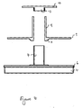
- an acoustic flooring system (1) at its lowest height setting comprising a flooring pedestal (2) supporting a number of flooring panels (3).
- the flooring pedestal (2) comprises a planar vibration-absorbing panel (4) in contact with the sub-flooring (5).
- the vibration-absorbing panel (4) is secured to the bottom of a planar pedestal base plate (6) having a threaded support pillar (7) extending upwards from the base plate (6) with a thread substantially along its full length.
- Engaged upon this support pillar (7) is a support plate (8) having a centrally located threaded aperture and threaded hollow tube (9).
- Attached to the top of the hollow tube is a locking member (10), with a threaded pillar (13).
- a small weld section (11) is present, which may preferably be machined to be planar with the support plate (8) so that this plate may be located closer to the base plate (6). Also illustrated is a planar vibration-absorbing panel (12) located on top of the support plate (8) and around the exterior of the hollow tube (9).
- FIG. 2 the system of Figure 1 is illustrated with the pedestal at its highest height setting.
- the figure also illustrates the presence of an optional locking nut (14) on the support pillar (7).
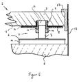
- an acoustic flooring system (1) at a perimeter wall (13) abutment comprising a flooring pedestal (2) in partial section supporting a flooring panel (3) shown in section.
- the flooring pedestal (2) comprises a planar vibration-absorbing panel (4) not shown in section in contact with the sub-flooring (5) shown in section.
- the vibration-absorbing panel (4) is secured to the bottom of a planar pedestal base plate (6) not shown in section having a threaded support pillar (7) not shown in section extending upwards from the base plate (6) with a thread substantially along its full length.
- Engaged upon this support pillar (7) is a support plate (8) shown in section having a centrally located threaded aperture and threaded hollow tube (9) shown in section.
- a small weld section (11) is present shown in section, which may preferably be machined to be planar with the support plate (8) so that this plate may be located closer to the base plate (6).
- a planar vibration-absorbing panel (12) shown in section located on top of the support plate (8) and around the exterior of the hollow tube (9).
- the figure also illustrates the presence of an optional locking nut (14) shown in section.
- the figure also illustrates the presence of a perimeter flanking strip (17) between the wall abutment (13) and the system components, in contact with the flooring panel (3). It is preferred that the perimeter flanking strip is a closed cell foam material.
- the perimeter flanking strip is between 4 and 20 mm in cross-section, more preferably 4 and 15 mm in cross-section, more preferably between 4 and 10 mm in cross-section and most preferably between 4 and 8 mm in cross-section.
- the arrangement in Figure 5 illustrates one possible arrangement for accommodating the flooring pedestal (2) of the present invention at the perimeter abutment of the flooring system.
- the flooring pedestal is located beneath a flooring panel edge and not necessarily at the junction of two panels.
- the underside (15) of the flooring panel (3) has a hole (16), which is capable of accommodating the threaded hollow tube (9) of the support plate (8).
- the hollow tube (9) is truncated compared to that illustrated in Figures 1 to 4 . There may be one or more of these flooring pedestals for each panel edge at the perimeter wall abutment.
- the arrangement in Figure 6 illustrates another possible arrangement for accommodating the flooring pedestal (2) of the present invention at the perimeter abutment of the flooring system where the final normal panel width falls short of reaching the perimeter abutment.
- the remaining gap to be bridged to the perimeter abutment is less than the width of a normal size panel.
- the flooring pedestal closest to the perimeter abutment is located beneath an oversized flooring panel and towards the edge of that panel proximate to the perimeter abutment and not necessarily at the junction of two panels.
- the underside (15) of the oversize flooring panel (3) has a hole (16), which is capable of accommodating the threaded hollow tube (9) of the support plate (8).
- the hollow tube (9) is truncated compared to that illustrated in Figures 1 to 4 . There may be one or more of these flooring pedestals for each panel edge at the perimeter wall abutment to conform to the specified loading requirements.
Landscapes
- Engineering & Computer Science (AREA)
- Architecture (AREA)
- Civil Engineering (AREA)
- Structural Engineering (AREA)
- General Engineering & Computer Science (AREA)
- Floor Finish (AREA)
Applications Claiming Priority (1)
| Application Number | Priority Date | Filing Date | Title |
|---|---|---|---|
| GBGB0805976.8A GB0805976D0 (en) | 2008-04-02 | 2008-04-02 | Flooring system |
Publications (2)
| Publication Number | Publication Date |
|---|---|
| EP2113619A2 true EP2113619A2 (de) | 2009-11-04 |
| EP2113619A3 EP2113619A3 (de) | 2010-12-01 |
Family
ID=39409935
Family Applications (1)
| Application Number | Title | Priority Date | Filing Date |
|---|---|---|---|
| EP09251041A Withdrawn EP2113619A3 (de) | 2008-04-02 | 2009-04-02 | Bodenbelagsystem |
Country Status (2)
| Country | Link |
|---|---|
| EP (1) | EP2113619A3 (de) |
| GB (1) | GB0805976D0 (de) |
Cited By (5)
| Publication number | Priority date | Publication date | Assignee | Title |
|---|---|---|---|---|
| WO2017178117A1 (de) * | 2016-04-14 | 2017-10-19 | Michael Schmitz | Bodenbelagelement und daraus bestehender fussboden |
| DE102016211636A1 (de) * | 2016-06-28 | 2017-12-28 | Veit Dennert Kg Baustoffbetriebe | Gebäudedecke, insbesondere für Holzhäuser, und Deckenelement dafür |
| DE202017104270U1 (de) | 2017-07-18 | 2018-10-24 | Ardex Anlagen Gmbh | Plattenlager für einen plattenförmigen Bodenbelag sowie Bodenbelagsanordung mit einem Plattenlager |
| US20230220681A1 (en) * | 2021-07-15 | 2023-07-13 | Global Integrated Flooring Solutions | Assemblies, devices, systems and methods relating to sound isolation between floors of a building |
| EP4257776A1 (de) * | 2022-04-08 | 2023-10-11 | Hertig Knut AB | Dämpfungsabstandshalter |
Citations (6)
| Publication number | Priority date | Publication date | Assignee | Title |
|---|---|---|---|---|
| GB2214537A (en) | 1988-01-25 | 1989-09-06 | Mackenzie Robin K | Sound attenuating flooring system |
| GB2219105A (en) | 1988-04-29 | 1989-11-29 | Ulstein Nor A S | Controlling a property of a mixture |
| GB2305947A (en) | 1996-01-30 | 1997-04-23 | Monarflex Ltd | Sound insulation of floors |
| GB2372515A (en) | 2001-01-24 | 2002-08-28 | Monarflex Ltd | Device for supporting battens |
| EP1584771A2 (de) | 2004-04-06 | 2005-10-12 | ETS-Lindgren, L.P. | Akustischer Fussboden mit niedrigem Profil |
| GB2420796A (en) | 2004-12-03 | 2006-06-07 | William Charles Ansell | Levelling cradle for supporting a flooring batten |
Family Cites Families (5)
| Publication number | Priority date | Publication date | Assignee | Title |
|---|---|---|---|---|
| US4258516A (en) * | 1978-06-16 | 1981-03-31 | Bridgestone Tire Company Limited | Apparatus for supporting floor plates above substrate |
| DE3807993A1 (de) * | 1988-03-10 | 1989-09-21 | Kolbermoor Faserbetonwerk | Doppelbodenplatte |
| JP3424099B2 (ja) * | 1992-12-25 | 2003-07-07 | 協同機材株式会社 | 建築用絶縁マット |
| JP2696782B2 (ja) * | 1993-04-14 | 1998-01-14 | 鐘紡株式会社 | 二重床用支持脚の高さ調整方法 |
| KR20070055095A (ko) * | 2005-11-25 | 2007-05-30 | 주식회사 엘지화학 | 이중 바닥재용 지지대 |
-
2008
- 2008-04-02 GB GBGB0805976.8A patent/GB0805976D0/en not_active Ceased
-
2009
- 2009-04-02 EP EP09251041A patent/EP2113619A3/de not_active Withdrawn
Patent Citations (6)
| Publication number | Priority date | Publication date | Assignee | Title |
|---|---|---|---|---|
| GB2214537A (en) | 1988-01-25 | 1989-09-06 | Mackenzie Robin K | Sound attenuating flooring system |
| GB2219105A (en) | 1988-04-29 | 1989-11-29 | Ulstein Nor A S | Controlling a property of a mixture |
| GB2305947A (en) | 1996-01-30 | 1997-04-23 | Monarflex Ltd | Sound insulation of floors |
| GB2372515A (en) | 2001-01-24 | 2002-08-28 | Monarflex Ltd | Device for supporting battens |
| EP1584771A2 (de) | 2004-04-06 | 2005-10-12 | ETS-Lindgren, L.P. | Akustischer Fussboden mit niedrigem Profil |
| GB2420796A (en) | 2004-12-03 | 2006-06-07 | William Charles Ansell | Levelling cradle for supporting a flooring batten |
Cited By (6)
| Publication number | Priority date | Publication date | Assignee | Title |
|---|---|---|---|---|
| WO2017178117A1 (de) * | 2016-04-14 | 2017-10-19 | Michael Schmitz | Bodenbelagelement und daraus bestehender fussboden |
| DE102016211636A1 (de) * | 2016-06-28 | 2017-12-28 | Veit Dennert Kg Baustoffbetriebe | Gebäudedecke, insbesondere für Holzhäuser, und Deckenelement dafür |
| DE202017104270U1 (de) | 2017-07-18 | 2018-10-24 | Ardex Anlagen Gmbh | Plattenlager für einen plattenförmigen Bodenbelag sowie Bodenbelagsanordung mit einem Plattenlager |
| EP3431680A1 (de) * | 2017-07-18 | 2019-01-23 | Ardex Anlagen GmbH | Plattenlager für einen plattenförmigen bodenbelag sowie bodenbelagsanordung mit einem plattenlager |
| US20230220681A1 (en) * | 2021-07-15 | 2023-07-13 | Global Integrated Flooring Solutions | Assemblies, devices, systems and methods relating to sound isolation between floors of a building |
| EP4257776A1 (de) * | 2022-04-08 | 2023-10-11 | Hertig Knut AB | Dämpfungsabstandshalter |
Also Published As
| Publication number | Publication date |
|---|---|
| GB0805976D0 (en) | 2008-05-07 |
| EP2113619A3 (de) | 2010-12-01 |
Similar Documents
| Publication | Publication Date | Title |
|---|---|---|
| US10301813B1 (en) | Portable core facility for a building | |
| US10724228B2 (en) | Building assemblies and methods for constructing a building using pre-assembled floor-ceiling panels and walls | |
| US10323428B2 (en) | Sequence for constructing a building from prefabricated components | |
| JP3248729B2 (ja) | 軽いゲージの鋼壁パネルを用いた高層建築物システム | |
| US10920414B2 (en) | Reinforcing structure for modular building construction | |
| US4914879A (en) | Prefabricated building system | |
| EP2113619A2 (de) | Bodenbelagsystem | |
| JP7769172B2 (ja) | 建物の施工方法 | |
| US11939778B2 (en) | Sound transmission control in cross laminated timber construction | |
| GB2571504A (en) | Buildings and methods of constructing buildings | |
| JP7582790B2 (ja) | 合成床構造およびその施工方法 | |
| US7975443B2 (en) | Precast prestress raised access floor construction | |
| JP6006551B2 (ja) | 建物 | |
| JP3911501B2 (ja) | 床施工方法 | |
| KR101642289B1 (ko) | 층간소음 방지를 위한 뜬바닥 어셈블리 | |
| JP5995738B2 (ja) | 建物 | |
| CA2615154A1 (en) | Method of building construction | |
| JP6856887B2 (ja) | 部材取付具及び建物 | |
| JP6325822B2 (ja) | 二重床構造を有する集合住宅の建物構造 | |
| US8429863B2 (en) | Prefabricated frame support | |
| US20220064934A1 (en) | Functional modules for factory-built homes | |
| JP3784122B2 (ja) | 建物の収納構造 | |
| WO2025008325A1 (en) | Floor frame assembly for modular building unit | |
| JP6427013B2 (ja) | 木造建物及びその外周壁構造 | |
| AU2001295296B2 (en) | Constructional element, building system and method of construction |
Legal Events
| Date | Code | Title | Description |
|---|---|---|---|
| PUAI | Public reference made under article 153(3) epc to a published international application that has entered the european phase |
Free format text: ORIGINAL CODE: 0009012 |
|
| AK | Designated contracting states |
Kind code of ref document: A2 Designated state(s): AT BE BG CH CY CZ DE DK EE ES FI FR GB GR HR HU IE IS IT LI LT LU LV MC MK MT NL NO PL PT RO SE SI SK TR |
|
| PUAL | Search report despatched |
Free format text: ORIGINAL CODE: 0009013 |
|
| AK | Designated contracting states |
Kind code of ref document: A3 Designated state(s): AT BE BG CH CY CZ DE DK EE ES FI FR GB GR HR HU IE IS IT LI LT LU LV MC MK MT NL NO PL PT RO SE SI SK TR |
|
| AX | Request for extension of the european patent |
Extension state: AL BA RS |
|
| 17P | Request for examination filed |
Effective date: 20110531 |
|
| 17Q | First examination report despatched |
Effective date: 20111207 |
|
| STAA | Information on the status of an ep patent application or granted ep patent |
Free format text: STATUS: THE APPLICATION IS DEEMED TO BE WITHDRAWN |
|
| 18D | Application deemed to be withdrawn |
Effective date: 20131105 |