EP2113680A2 - Appareil incluant un support hydraulique fluide MR - Google Patents
Appareil incluant un support hydraulique fluide MR Download PDFInfo
- Publication number
- EP2113680A2 EP2113680A2 EP09158463A EP09158463A EP2113680A2 EP 2113680 A2 EP2113680 A2 EP 2113680A2 EP 09158463 A EP09158463 A EP 09158463A EP 09158463 A EP09158463 A EP 09158463A EP 2113680 A2 EP2113680 A2 EP 2113680A2
- Authority
- EP
- European Patent Office
- Prior art keywords
- fluid
- partition plate
- mount
- plate assembly
- pressure sensor
- Prior art date
- Legal status (The legal status is an assumption and is not a legal conclusion. Google has not performed a legal analysis and makes no representation as to the accuracy of the status listed.)
- Withdrawn
Links
Images


Classifications
-
- F—MECHANICAL ENGINEERING; LIGHTING; HEATING; WEAPONS; BLASTING
- F16—ENGINEERING ELEMENTS AND UNITS; GENERAL MEASURES FOR PRODUCING AND MAINTAINING EFFECTIVE FUNCTIONING OF MACHINES OR INSTALLATIONS; THERMAL INSULATION IN GENERAL
- F16F—SPRINGS; SHOCK-ABSORBERS; MEANS FOR DAMPING VIBRATION
- F16F13/00—Units comprising springs of the non-fluid type as well as vibration-dampers, shock-absorbers, or fluid springs
- F16F13/04—Units comprising springs of the non-fluid type as well as vibration-dampers, shock-absorbers, or fluid springs comprising both a plastics spring and a damper, e.g. a friction damper
- F16F13/26—Units comprising springs of the non-fluid type as well as vibration-dampers, shock-absorbers, or fluid springs comprising both a plastics spring and a damper, e.g. a friction damper characterised by adjusting or regulating devices responsive to exterior conditions
- F16F13/30—Units comprising springs of the non-fluid type as well as vibration-dampers, shock-absorbers, or fluid springs comprising both a plastics spring and a damper, e.g. a friction damper characterised by adjusting or regulating devices responsive to exterior conditions comprising means for varying fluid viscosity, e.g. of magnetic or electrorheological fluids
- F16F13/305—Units comprising springs of the non-fluid type as well as vibration-dampers, shock-absorbers, or fluid springs comprising both a plastics spring and a damper, e.g. a friction damper characterised by adjusting or regulating devices responsive to exterior conditions comprising means for varying fluid viscosity, e.g. of magnetic or electrorheological fluids magnetorheological
-
- F—MECHANICAL ENGINEERING; LIGHTING; HEATING; WEAPONS; BLASTING
- F16—ENGINEERING ELEMENTS AND UNITS; GENERAL MEASURES FOR PRODUCING AND MAINTAINING EFFECTIVE FUNCTIONING OF MACHINES OR INSTALLATIONS; THERMAL INSULATION IN GENERAL
- F16F—SPRINGS; SHOCK-ABSORBERS; MEANS FOR DAMPING VIBRATION
- F16F2230/00—Purpose; Design features
- F16F2230/08—Sensor arrangement
Definitions
- the present invention relates generally to hydraulic mounts, and more particularly to apparatus including an MR-fluid (magnetorheological-fluid) hydraulic mount.
- MR-fluid hydraulic mounts include those which are attachable to first and second motor-vehicle components (such as an automobile engine or transmission and an automobile body/frame) and which have a pumping chamber and a reservoir chamber.
- the pumping and reservoir chambers are separated by a partition plate having a through hole.
- These mounts also have an electric coil which magnetically influences the through hole.
- Magnetorheological fluid is placed in the pumping and reservoir chambers and in the through hole.
- MR-fluid hydraulic-mounts examples are found in U.S. Patent Serial No. 6,622,995 and in US Patent Application Publication No. 2005/0230890 .
- An example of a hydraulic mount having an integral controller is found in US Patent Application Publication No. 2005/0029720 .
- a first expression of an embodiment of the invention is for apparatus including an MR-fluid hydraulic mount.
- the mount includes an internal MR-fluid cavity and a partition plate assembly.
- the partition plate assembly partitions the cavity into first and second MR-fluid chambers.
- the mount is adapted to receive an MR-fluid pressure sensor in fluid communication with the second MR-fluid chamber.
- a second expression of an embodiment of the invention is for apparatus including an MR-fluid hydraulic mount.
- the mount includes an internal MR-fluid cavity, a partition plate assembly, and an MR-fluid pressure sensor.
- the partition plate assembly partitions the cavity into first and second MR-fluid chambers.
- the MR-fluid pressure sensor is in fluid communication with the second MR-fluid chamber.
- the MR-fluid hydraulic mount is installed in a vehicle and is controlled by using at least a fluid pressure within the second MR-fluid chamber obtained by using the MR-fluid pressure sensor. This avoids problems of controlling the mount using a position or velocity sensor to determine compression and rebound of the mount, such problems including noise, reliability of the position/velocity sensor arm attachment, packaging of the position/velocity sensor, and assembly cost of the position/velocity sensor.
- Figure 1 is a longitudinal cross-sectional schematic view of an embodiment of an MR-fluid (magnetorheological-fluid) hydraulic mount of the invention
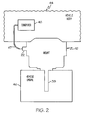
- Figure 2 is a diagram showing the mount of figure 1 attached to a vehicle body and a vehicle engine;
- Figure 3 is a flow chart of a first method for controlling an MR-fluid hydraulic mount, such as the mount of figures 1-2 ;
- Figure 4 is a diagram of a low-pass filter which can be used to filter a delta pressure in performing the first method of figure 3 .
- FIG. 1 A first expression of the embodiment of figure 1-2 is for apparatus 10 including an MR-fluid (magnetorheological-fluid) hydraulic mount 12.
- the mount 12 includes an internal MR-fluid cavity 14 and a partition plate assembly 16.
- the partition plate assembly 16 partitions the cavity 14 into first and second MR-fluid chambers 18 and 20.
- the mount 12 is adapted to receive an MR-fluid pressure sensor 22 in fluid communication with the second MR-fluid chamber 20.
- the mount 12 includes a base plate 24 and a housing 26, wherein the partition plate assembly 16 is disposed between and fixedly attached to the base plate 24 and the housing 26.
- the mount 12 includes an MR-fluid-sealing assembly 28 including a first portion 30 and a second portion 32, wherein the first portion 30 partially defines the first MR-fluid chamber 18 and wherein the second portion 32 partially defines the second MR-fluid chamber 20.
- the first portion 30 includes a flexible diaphragm 34 which is disposed between the base plate 24 and the partition plate assembly 16.
- the second portion 32 includes a flexible molded assembly 36 which is less flexible than the diaphragm 34 and which is attached to the housing 26.
- the mount 12 includes a mounting stud assembly 38 which is attached to the molded assembly 36.
- the partition plate assembly 16 includes an orifice 40 extending from the first MR-fluid chamber 18 to the second MR-fluid chamber 20, and the mount 12 includes an electric coil 42 disposed to magnetically influence the orifice 40.
- the base plate 24 is adapted to be attached to a vehicle body 44
- the mounting stud assembly 38 is adapted to be attached to a vehicle engine 46 (providing an engine hanging mount)
- the MR-fluid pressure sensor 22 is operatively connectable (such as by a cable 47) to a vehicle computer 48 adapted to determine a command electric current to be applied to the electric coil 42.
- the partition plate assembly 16 includes a port 50 adapted to receive the MR-fluid pressure sensor 22.
- the partition plate assembly 16 includes a passageway 52 extending from the port 50 to the second MR-fluid chamber 20.
- the housing 26 includes a port (not shown) adapted to receive the MR-fluid pressure sensor 22.
- Other examples are left to the artisan.
- the partition plate assembly 16 may be thick or thin and may be monolithic or made of a plurality of parts.
- the orifice 40 is disposed radially outward of the electric coil 42, and the partition plate assembly 16 is devoid of any decoupler and is devoid of any non-MR-fluid orifice.
- the first MR-fluid chamber 18 is a reservoir chamber and the second MR-fluid chamber 20 is a pumping chamber.
- a second expression of the embodiment of figures 1-2 is for apparatus 10 including an MR-fluid hydraulic mount 12.
- the mount 12 includes an internal MR-fluid cavity 14, a partition plate assembly 16, and an MR-fluid pressure sensor 22.
- the partition plate assembly 16 partitions the cavity into first and second MR-fluid chambers 18 and 20.
- the MR-fluid pressure sensor 22 is in fluid communication with the second MR-fluid chamber 20.
- the MR-fluid pressure sensor 22 is attached to the partition plate assembly 16.
- the partition plate assembly 16 includes a passageway 52 extending from the MR-fluid pressure sensor 22 to the second MR-fluid chamber 20.
- a first method of the invention is for controlling an MR-fluid hydraulic mount 12 connected to a vehicle engine 46.
- the mount 12 includes an internal MR-fluid cavity 14 and includes a partition plate assembly 16 partitioning the cavity 14 into first and second MR-fluid chambers 18 and 20.
- the partition plate assembly 16 has an orifice 40 extending from the first MR-fluid chamber 18 to the second MR-fluid chamber 20, and the mount 12 includes an electric coil 42 disposed to magnetically influence the orifice 40.
- the first method includes steps a) through d). Step a) is labeled as "Determine Reference Pressure For Idle Engine" in block 54 of figure 3 .
- Step a) includes, when the vehicle engine 46 is at idle, determining a reference pressure as a fluid pressure within the second MR-fluid chamber 20.
- Step b) is labeled as "Calculate Delta Pressure For Above-Idle Engine” in block 56 of figure 3 .
- Step b) includes, when the vehicle engine 46 is above idle, calculating a delta pressure as a difference between a previous fluid pressure and a current fluid pressure within the second MR-fluid chamber 20.
- Step c) is labeled as "Determine First Dead-Band Value" in block 58 of figure 3 .
- Step c) includes determining a first dead-band value using at least a difference between the reference pressure and the current fluid pressure.
- Step d) is labeled as "Determine First Current To Be Applied To The Electric Coil" in block 60 of figure 3 .
- Step d) includes, when the delta pressure is greater than the first dead-band value, determining a first command electric current to be applied to the electric coil 42 using at least the difference between the reference pressure and the current fluid pressure and applying the first command electric current to the electric coil 42.
- step a) is performed every time the vehicle engine 46 is at idle. In another variation, step a) is performed one time during an engine cycle (engine turn on to engine turn off) the first time the vehicle engine 46 is at idle.
- the first method also includes determining a second dead-band value using at least the difference between the reference pressure and the current fluid pressure.
- step d) sets the first command electric current to zero when the difference between the reference pressure and the current fluid pressure is not greater than the second dead-band value.
- step e) includes, when the delta pressure is not greater than the first dead-band value, setting the first command electric current to zero.
- step e) includes, when the delta pressure is not greater than the first dead-band value, determining a second command electric current to be applied to the electric coil 42 using at least the difference between the reference pressure and the current pressure and applying the second command electric current to the electric coil 42.
- step c) includes determining the first dead-band value using at least the difference between the reference pressure and the current pressure for a particular vehicle event.
- step c) includes determining the first dead-band value using at least the difference between the reference pressure and the current pressure for the particular vehicle event and for a particular vehicle speed.
- An example of a vehicle-speed-dependent vehicle event is a rough road.
- the first and second dead-band values are experimentally determined (and stored in lookup tables) for desirable driver/passenger comfort and desirable vehicle performance for each vehicle model for different values of delta pressure.
- the first and second command electric currents are also experimentally determined (and stored in lookup tables) for desirable driver/passenger comfort and desirable vehicle performance for each vehicle model for different values of the difference between the reference pressure and the current fluid pressure. It is noted that a positive delta pressure indicates the mount 12 is undergoing compression and that a negative delta pressure indicates the mount 12 is undergoing rebound.
- a time interval of substantially one millisecond exists between the previous fluid pressure and the current fluid pressure.
- the first and second MR-fluid chambers 18 and 20 and the orifice 40 (and the passageway 52) contain MR fluid 66.
- a second method of the invention is for controlling an MR-fluid hydraulic mount 12 connected to a vehicle engine 46.
- the mount 12 includes an internal MR-fluid cavity 14 and a partition plate assembly 16 partitioning the cavity 14 into first and second MR-fluid chambers 18 and 20.
- the mount 12 includes an MR-fluid pressure sensor 22 in fluid communication with the second MR-fluid chamber 20.
- the partition plate assembly 16 has an orifice 40 extending from the first MR-fluid chamber 18 to the second MR-fluid chamber 20.
- the mount 12 includes an electric coil 42 disposed to magnetically influence the orifice 40.
- the second method includes steps a) through d).
- Step a) includes, when the vehicle engine 46 is at idle, determining a reference pressure as a fluid pressure within the second MR-fluid chamber 20 using the MR-fluid pressure sensor 22.
- Step b) includes; when the vehicle engine 46 is above idle, calculating a delta pressure as a difference between a previous fluid pressure and a current fluid pressure within the second MR-fluid chamber 20, wherein the previous and current fluid pressures are obtained using the MR-fluid pressure sensor 22.
- Step c) includes determining a first dead-band value using at least a difference between the reference pressure and the current fluid pressure.
- Step d) includes, when the delta pressure is greater than the first dead-band value, determining a first command electric current to be applied to the electric coil 42 using at least the difference between the reference pressure and the current fluid pressure and applying the first command electric current to the electric coil 42.
- a third method of the invention which is broader than the first and second methods, is for controlling an MR-fluid hydraulic mount 12 connected to a vehicle engine 46.
- the mount 12 includes an internal MR-fluid cavity 14 and includes a partition plate assembly 16 partitioning the cavity 14 into first and second MR-fluid chambers 18 and 20.
- the partition plate assembly 16 has an orifice 40 extending from the first MR-fluid chamber 18 to the second MR-fluid chamber 20.
- the mount 12 includes an electric coil 42 disposed to magnetically influence the orifice 40
- the third method includes steps a) through c). Step a) includes, when the vehicle engine 46 is at idle, determining a reference pressure as a fluid pressure within the second MR-fluid chamber 20.
- Step b) includes, when the vehicle engine 46 is above idle, determining a command electric current to be applied to the electric coil 42 using at least a difference between the reference pressure and a current fluid pressure within the second MR-fluid chamber 20.
- Step c) includes applying the command electric output current to the electric coil.
- the mount 12 includes an MR-fluid pressure sensor 22 in fluid communication with the second MR-fluid chamber 20, and the reference, previous and current fluid pressures are obtained using the MR-fluid pressure sensor 22.
- the MR-fluid hydraulic mount is installed in a vehicle and is controlled by using at least a fluid pressure within the second MR-fluid chamber obtained by using the MR-fluid pressure sensor. This avoids problems of controlling the mount using a position or velocity sensor to determine compression and rebound of the mount, such problems including noise, reliability of the position/velocity sensor arm attachment, packaging of the position/velocity sensor, and assembly cost of the position/velocity sensor.
Landscapes
- Engineering & Computer Science (AREA)
- General Engineering & Computer Science (AREA)
- Mechanical Engineering (AREA)
- Combined Devices Of Dampers And Springs (AREA)
- Fluid-Damping Devices (AREA)
- Arrangement Or Mounting Of Propulsion Units For Vehicles (AREA)
Applications Claiming Priority (1)
| Application Number | Priority Date | Filing Date | Title |
|---|---|---|---|
| US12/150,938 US20090273128A1 (en) | 2008-05-01 | 2008-05-01 | Apparatus including an MR-fluid hydraulic mount |
Publications (2)
| Publication Number | Publication Date |
|---|---|
| EP2113680A2 true EP2113680A2 (fr) | 2009-11-04 |
| EP2113680A3 EP2113680A3 (fr) | 2010-11-03 |
Family
ID=40940386
Family Applications (1)
| Application Number | Title | Priority Date | Filing Date |
|---|---|---|---|
| EP09158463A Withdrawn EP2113680A3 (fr) | 2008-05-01 | 2009-04-22 | Appareil incluant un support hydraulique fluide MR |
Country Status (2)
| Country | Link |
|---|---|
| US (1) | US20090273128A1 (fr) |
| EP (1) | EP2113680A3 (fr) |
Families Citing this family (1)
| Publication number | Priority date | Publication date | Assignee | Title |
|---|---|---|---|---|
| JP6257230B2 (ja) * | 2013-09-06 | 2018-01-10 | 住友理工株式会社 | 流体封入式防振装置 |
Citations (3)
| Publication number | Priority date | Publication date | Assignee | Title |
|---|---|---|---|---|
| US6622995B2 (en) | 2001-05-16 | 2003-09-23 | Delphi Technologies, Inc. | Hydraulic mount with magnetorheological fluid |
| US20050029720A1 (en) | 2003-08-07 | 2005-02-10 | Bodie Mark O. | Bi-state hydraulic mount with integral controller |
| US20050230890A1 (en) | 2004-04-16 | 2005-10-20 | Tewani Sanjiv G | Magnetorheological-fluid hydraulic mount |
Family Cites Families (11)
| Publication number | Priority date | Publication date | Assignee | Title |
|---|---|---|---|---|
| JPH01312242A (ja) * | 1988-06-13 | 1989-12-18 | Nissan Motor Co Ltd | 粘度可変流体封入制御型防振体 |
| JPH0781605B2 (ja) * | 1989-02-01 | 1995-09-06 | 東海ゴム工業株式会社 | 電気粘性流体使用装置 |
| US5029823A (en) * | 1989-10-30 | 1991-07-09 | Lord Corporation | Vibration isolator with electrorheological fluid controlled dynamic stiffness |
| US20020153647A1 (en) * | 2001-04-23 | 2002-10-24 | Delphi Technologies Inc. | Hydraulic mount and control method |
| US6412761B1 (en) * | 2001-04-25 | 2002-07-02 | Delphi Technologies, Inc. | Hybrid hydraulic mount with magnetorheological fluid chamber |
| US6754571B2 (en) * | 2001-07-30 | 2004-06-22 | Delphi Technologies, Inc. | Control of magnetorheological engine mount |
| US6880483B2 (en) * | 2003-02-07 | 2005-04-19 | Delphi Technologies, Inc. | Active seat suspension for watercraft |
| US7063191B2 (en) * | 2004-02-10 | 2006-06-20 | Delphi Technologies, Inc. | Reversed decoupler assembly for MR mount |
| US7510061B2 (en) * | 2005-12-27 | 2009-03-31 | Delphi Technologies, Inc. | MR-fluid hydraulic mount |
| DE102006051605B4 (de) * | 2006-11-02 | 2010-01-14 | Dr. Ing. H.C. F. Porsche Aktiengesellschaft | Vorrichtung und Verfahren zur Steuerung eines Lagerelements |
| US20090276098A1 (en) * | 2008-05-01 | 2009-11-05 | Bodie Mark O | Method for controlling an MR-fluid hydraulic mount connected to a vehicle engine |
-
2008
- 2008-05-01 US US12/150,938 patent/US20090273128A1/en not_active Abandoned
-
2009
- 2009-04-22 EP EP09158463A patent/EP2113680A3/fr not_active Withdrawn
Patent Citations (3)
| Publication number | Priority date | Publication date | Assignee | Title |
|---|---|---|---|---|
| US6622995B2 (en) | 2001-05-16 | 2003-09-23 | Delphi Technologies, Inc. | Hydraulic mount with magnetorheological fluid |
| US20050029720A1 (en) | 2003-08-07 | 2005-02-10 | Bodie Mark O. | Bi-state hydraulic mount with integral controller |
| US20050230890A1 (en) | 2004-04-16 | 2005-10-20 | Tewani Sanjiv G | Magnetorheological-fluid hydraulic mount |
Also Published As
| Publication number | Publication date |
|---|---|
| EP2113680A3 (fr) | 2010-11-03 |
| US20090273128A1 (en) | 2009-11-05 |
Similar Documents
| Publication | Publication Date | Title |
|---|---|---|
| EP2113681B1 (fr) | Procédé de contrôle d'un support hydraulique fluide MR connecté à un moteur de véhicule | |
| US11529835B2 (en) | Electronically controlled external damper reservoir | |
| US20180015802A1 (en) | Device and method for estimating damper force and damper velocity in active suspension system | |
| EP0752331A2 (fr) | Commande pour suspension de véhicule automobile | |
| US9205819B2 (en) | Electronic control device for a braking system, suitable for a distance control system | |
| KR20140131390A (ko) | 브레이크 시스템을 작동시키는 방법 및 브레이크 시스템 | |
| US20100121548A1 (en) | Correction method for the correction of characteristic curves for analogized hydraulic valves in motor vehicle braking systems | |
| KR20150095736A (ko) | 자동차 브레이크 시스템의 공압 브레이크 부스터를 위한 진공 공급 방법 | |
| US9573575B2 (en) | Method for operating a brake booster of a vehicle and control device for a break booster of a vehicle | |
| KR101978004B1 (ko) | 압력 설정 정확도를 최적화하는 방법 | |
| JP2013519580A (ja) | 車両の液圧式ブレーキシステムを作動する方法および車両の液圧式ブレーキシステムのための制御装置 | |
| US11321974B2 (en) | Method and system for carrying out an on-board diagnostic function of a vehicle | |
| CN110550009B (zh) | 用于控制液压制动系统的方法 | |
| EP2113680A2 (fr) | Appareil incluant un support hydraulique fluide MR | |
| US20060113837A1 (en) | Vehicle motion control apparatus | |
| US9248816B2 (en) | Hydraulic unit with variable damping | |
| US7853387B2 (en) | Controller for operation of vehicle and control method for the same | |
| CN116096610B (zh) | 对车辆的配备有机动化的活塞缸设备的制动系统进行参数估计的设备和方法 | |
| KR20190039285A (ko) | 잠김 방지 조절 프로세스를 실행하도록 설계된 브레이크 시스템의 전기 기계 브레이크 부스터를 작동시키기 위한 제어 장치 및 방법 | |
| US11447115B2 (en) | Brake fluid pressure control device | |
| JP6501833B2 (ja) | アクティブ・パワートレイン・マウントの制御システム | |
| US20240416702A1 (en) | Method for controlling a hydraulic actuator of an active chassis | |
| CN116572757B (zh) | 车辆控制方法、装置、车辆和存储介质 | |
| KR101243078B1 (ko) | 차량용 전자제어유닛 | |
| CN108137013B (zh) | 电子制动压力调节系统 |
Legal Events
| Date | Code | Title | Description |
|---|---|---|---|
| PUAI | Public reference made under article 153(3) epc to a published international application that has entered the european phase |
Free format text: ORIGINAL CODE: 0009012 |
|
| AK | Designated contracting states |
Kind code of ref document: A2 Designated state(s): AT BE BG CH CY CZ DE DK EE ES FI FR GB GR HR HU IE IS IT LI LT LU LV MC MK MT NL NO PL PT RO SE SI SK TR |
|
| PUAL | Search report despatched |
Free format text: ORIGINAL CODE: 0009013 |
|
| AK | Designated contracting states |
Kind code of ref document: A3 Designated state(s): AT BE BG CH CY CZ DE DK EE ES FI FR GB GR HR HU IE IS IT LI LT LU LV MC MK MT NL NO PL PT RO SE SI SK TR |
|
| AX | Request for extension of the european patent |
Extension state: AL BA RS |
|
| 17P | Request for examination filed |
Effective date: 20110428 |
|
| 17Q | First examination report despatched |
Effective date: 20110627 |
|
| STAA | Information on the status of an ep patent application or granted ep patent |
Free format text: STATUS: THE APPLICATION IS DEEMED TO BE WITHDRAWN |
|
| 18D | Application deemed to be withdrawn |
Effective date: 20111108 |