EP2113682A2 - Agencement d'amortissement des oscillations de torsion pour la chaîne cinématique d'un véhicule - Google Patents
Agencement d'amortissement des oscillations de torsion pour la chaîne cinématique d'un véhicule Download PDFInfo
- Publication number
- EP2113682A2 EP2113682A2 EP20090158423 EP09158423A EP2113682A2 EP 2113682 A2 EP2113682 A2 EP 2113682A2 EP 20090158423 EP20090158423 EP 20090158423 EP 09158423 A EP09158423 A EP 09158423A EP 2113682 A2 EP2113682 A2 EP 2113682A2
- Authority
- EP
- European Patent Office
- Prior art keywords
- throttle
- fluid
- arrangement
- torsional vibration
- vibration damper
- Prior art date
- Legal status (The legal status is an assumption and is not a legal conclusion. Google has not performed a legal analysis and makes no representation as to the accuracy of the status listed.)
- Withdrawn
Links
- 230000005540 biological transmission Effects 0.000 title description 8
- 230000010355 oscillation Effects 0.000 title description 5
- 239000012530 fluid Substances 0.000 claims abstract description 125
- 230000009471 action Effects 0.000 claims abstract description 8
- 230000000712 assembly Effects 0.000 claims description 24
- 238000000429 assembly Methods 0.000 claims description 24
- 230000003993 interaction Effects 0.000 claims description 16
- 230000001965 increasing effect Effects 0.000 claims description 12
- 230000001133 acceleration Effects 0.000 claims description 8
- 230000006698 induction Effects 0.000 claims description 5
- 230000005684 electric field Effects 0.000 claims description 3
- 238000005086 pumping Methods 0.000 claims description 3
- 230000001419 dependent effect Effects 0.000 claims 1
- 238000004146 energy storage Methods 0.000 abstract description 10
- 230000005284 excitation Effects 0.000 description 14
- 230000000694 effects Effects 0.000 description 8
- 230000000737 periodic effect Effects 0.000 description 5
- 238000013016 damping Methods 0.000 description 4
- 230000006835 compression Effects 0.000 description 3
- 238000007906 compression Methods 0.000 description 3
- 230000008878 coupling Effects 0.000 description 3
- 238000010168 coupling process Methods 0.000 description 3
- 238000005859 coupling reaction Methods 0.000 description 3
- 238000006073 displacement reaction Methods 0.000 description 3
- ORQBXQOJMQIAOY-UHFFFAOYSA-N nobelium Chemical compound [No] ORQBXQOJMQIAOY-UHFFFAOYSA-N 0.000 description 3
- 230000008901 benefit Effects 0.000 description 2
- 238000004891 communication Methods 0.000 description 2
- 238000010276 construction Methods 0.000 description 2
- 238000009795 derivation Methods 0.000 description 2
- 230000001939 inductive effect Effects 0.000 description 2
- 230000007935 neutral effect Effects 0.000 description 2
- 238000007789 sealing Methods 0.000 description 2
- 230000004913 activation Effects 0.000 description 1
- 229910052782 aluminium Inorganic materials 0.000 description 1
- XAGFODPZIPBFFR-UHFFFAOYSA-N aluminium Chemical compound [Al] XAGFODPZIPBFFR-UHFFFAOYSA-N 0.000 description 1
- 230000015572 biosynthetic process Effects 0.000 description 1
- 230000008859 change Effects 0.000 description 1
- 238000002485 combustion reaction Methods 0.000 description 1
- 230000001351 cycling effect Effects 0.000 description 1
- 230000006837 decompression Effects 0.000 description 1
- 230000007423 decrease Effects 0.000 description 1
- 229920001971 elastomer Polymers 0.000 description 1
- 239000000806 elastomer Substances 0.000 description 1
- 230000007257 malfunction Effects 0.000 description 1
- 239000000463 material Substances 0.000 description 1
- 239000002923 metal particle Substances 0.000 description 1
- 230000000750 progressive effect Effects 0.000 description 1
- 230000004044 response Effects 0.000 description 1
- 230000002441 reversible effect Effects 0.000 description 1
- 239000007787 solid Substances 0.000 description 1
- 230000007704 transition Effects 0.000 description 1
- 230000001960 triggered effect Effects 0.000 description 1
Images







Classifications
-
- F—MECHANICAL ENGINEERING; LIGHTING; HEATING; WEAPONS; BLASTING
- F16—ENGINEERING ELEMENTS AND UNITS; GENERAL MEASURES FOR PRODUCING AND MAINTAINING EFFECTIVE FUNCTIONING OF MACHINES OR INSTALLATIONS; THERMAL INSULATION IN GENERAL
- F16F—SPRINGS; SHOCK-ABSORBERS; MEANS FOR DAMPING VIBRATION
- F16F15/00—Suppression of vibrations in systems; Means or arrangements for avoiding or reducing out-of-balance forces, e.g. due to motion
- F16F15/10—Suppression of vibrations in rotating systems by making use of members moving with the system
- F16F15/16—Suppression of vibrations in rotating systems by making use of members moving with the system using a fluid or pasty material
- F16F15/162—Suppression of vibrations in rotating systems by making use of members moving with the system using a fluid or pasty material with forced fluid circulation
-
- F—MECHANICAL ENGINEERING; LIGHTING; HEATING; WEAPONS; BLASTING
- F16—ENGINEERING ELEMENTS AND UNITS; GENERAL MEASURES FOR PRODUCING AND MAINTAINING EFFECTIVE FUNCTIONING OF MACHINES OR INSTALLATIONS; THERMAL INSULATION IN GENERAL
- F16F—SPRINGS; SHOCK-ABSORBERS; MEANS FOR DAMPING VIBRATION
- F16F15/00—Suppression of vibrations in systems; Means or arrangements for avoiding or reducing out-of-balance forces, e.g. due to motion
- F16F15/10—Suppression of vibrations in rotating systems by making use of members moving with the system
- F16F15/12—Suppression of vibrations in rotating systems by making use of members moving with the system using elastic members or friction-damping members, e.g. between a rotating shaft and a gyratory mass mounted thereon
- F16F15/121—Suppression of vibrations in rotating systems by making use of members moving with the system using elastic members or friction-damping members, e.g. between a rotating shaft and a gyratory mass mounted thereon using springs as elastic members, e.g. metallic springs
Definitions
- the present invention relates to a torsional vibration damper arrangement, in particular for the drive train of a vehicle, comprising a primary side and a secondary side rotatable against the action of a damper assembly with respect to the primary side about a rotation axis, wherein the damper assembly comprises at least one fluid pressure accumulator assembly and a conveyor assembly through which upon relative rotation of the primary side with regard to the secondary side, the fluid storage pressure in at least one fluid pressure accumulator arrangement can be increased, wherein the at least one fluid pressure accumulator arrangement comprises at least one fluid pressure accumulator unit on one side of the primary side and secondary side with first fluid which can be conveyed by the conveyor arrangement and an energy accumulator which can be loaded by the first fluid.
- Torsionsschwingungsdämpferansseneranssenen serve, for example, in the drive train of vehicles to dampen in the torque transmission path between a drive unit and a gear rotational irregularities such as load cycling or generated by a used as a drive unit internal combustion engine with the periodic ignitions vibration excitations or to prevent their transmission in the following drive train.
- arrangements designed as so-called gas spring torsional vibration dampers have proven to be particularly advantageous, since they have an excellent damping characteristic in a wide range of vibration excitations.
- a Torsionsschwingungsdämpferan Aunt in particular for the drive train of a vehicle, comprising a primary side and against the action of a damper assembly with respect to the primary side about a rotation rotatable secondary side
- the damper assembly comprises at least one fluid pressure accumulator assembly and a conveyor assembly through which during relative rotation the primary side with respect to the secondary side of the fluid storage pressure in at least one fluid pressure accumulator assembly can be increased
- the at least one fluid pressure accumulator assembly comprises on one side of the primary side and secondary side at least one fluid pressure accumulator unit with the first fluid conveyable by the conveyor assembly and a loadable by the first fluid energy storage, wherein in a flow path of the first fluid to at least one energy storage device, a throttle arrangement with variable throttle behavior is provided ,
- the effect of the switchability of a pressure accumulator according to the invention can be used in a particularly efficient and variable manner in that at least one fluid pressure accumulator arrangement has a plurality of energy accumulators with associated throttle arrangements and the energy accumulators can be switched in parallel by the associated throttle arrangements.
- At least one throttle arrangement comprises a throttle element which can be arranged by a drive unit.
- At least one throttle arrangement comprises a throttle element which can be arranged by a drive unit.
- the throttle element be displaceable or rotatable by the associated drive unit.
- a deformability of the throttle element by the associated drive unit and thus the more or less strong closing, for example, a throttle opening is a design option.
- At least one drive unit by electrical and / or magnetic interaction acts to provide the throttle element. It can be provided that at least one drive unit in association with a throttle arrangement on the one side of the primary side and the secondary side comprises an electromagnet assembly.
- At least one drive unit can be supplied by sliding contact or induction with drive signals and / or electrical drive energy.
- At least one drive unit is arranged in a non-rotating system area and is designed to generate a magnetic or / and electrical interaction with an interaction region of one or more throttle arrangements.
- At least one drive unit may comprise at least one electromagnet arrangement.
- at least one drive unit comprises at least one permanent magnet which is preferably displaceable for generating a magnetic interaction.
- At least one drive unit comprises a mechanical drive which derives a drive force from a relative rotation between the primary side and the secondary side. Since in this embodiment of the control, the relative rotation between the primary side and the secondary side is based, it is possible to always use the current operating state of the torsional vibration damper arrangement for adjusting the throttle behavior in a simple manner.
- the mechanical drive is designed as a cam drive.
- the mechanical drive is designed as a lever drive.
- At least one drive unit is designed as a pressurized fluid drive.
- At least one drive unit comprises a bimetallic drive element which can be deformed as a function of a temperature of the first fluid.
- Another way to influence the flow of the first fluid and thus the throttle behavior of a throttle arrangement is that the first fluid is magneto-rheological and / or electro-rheological and that at least one throttle arrangement, a device for generating an electric field and / or magnetic field in the flow path of the first fluid comprises.
- This variant is therefore particularly advantageous because no components to be moved are required to obtain the variation of the throttle behavior and thus on the one hand the risk of wear or a mechanical malfunction can be excluded, on the other hand, an influence on the control behavior, for example by centrifugal forces not will occur.
- At least one throttle arrangement comprises a throttle element adjustable as a function of a rotational acceleration of the primary side and / or the secondary side.
- the throttle element a this is assigned in at least one direction of adjustment periodically acting drive unit.
- This periodic application can be achieved, for example, by virtue of the fact that the drive unit comprises at least one drive mass element that is movable approximately in a circumferential direction against a restoring force.
- At least one energy store comprises compressible second fluid, preferably gas, in a storage volume.
- the compression of gas has proven to be particularly advantageous due to the damping behavior that can be achieved thereby.
- an energy store may also comprise one or more springs, for example helical compression springs or compressible solids, such as e.g. Elastomer blocks or the like, use.
- springs for example helical compression springs or compressible solids, such as e.g. Elastomer blocks or the like, use.
- various energy storage media such as e.g. a spring and a compressible fluid, e.g. Gas, to combine.
- the conveying arrangement comprises a pump arrangement that can be driven by relative rotation of the primary side with respect to the secondary side, which conveys first fluid from one of the fluid pressure accumulator arrangements to the other fluid pressure accumulator arrangement as a function of the relative direction of rotation.
- pumping arrangements operating, in particular, without rotation angle limitation, such as e.g. Gear pumps or the like advantageous because they allow a very soft damper characteristic without the risk that the primary side and the secondary side come into mutual attack.
- the conveyor arrangement comprises at least one pressure chamber formed between the primary side and the secondary side, the volume of which can be changed with relative rotation of the primary side with respect to the secondary side, and at least one connecting volume via which the first chamber displaced from the at least one pressure chamber Fluid loaded at least one energy storage.
- the Fig. 1 shows in cross-section, relative to a rotation axis A, a Torsionsschwingungsdämpferan extract 10, which is constructed in the manner of a gas spring torsional vibration damper.
- a primary side 12 of this Torsionsschwingungsdämpferan effet 10 includes an outer housing 14, with which a plurality of star-shaped around the rotation axis A around arranged and effective as a pressure accumulator gas spring units 16 is rotatably coupled.
- a secondary side 18 of the torsional vibration damper assembly 10 comprises an inner housing part 20, which is basically rotatable relative to the outer housing part 14 about the axis of rotation A.
- the outer housing part 14 has two radially inward extending, wing-like walls 22, 22 'on.
- the radially inner housing part 20 has two radially outwardly extending wing-like walls 24, 24 '.
- the walls 22, 22 ', 24, 24' lie under the use of respective sealing elements radially inward or radially outwardly fluid-tight on the respective other housing part, so that four pressure chambers 26, 28, 26 ', 28' are formed in the circumferential direction.
- These are of course closed fluid-tight in the axial direction by terminating elements, which are preferably arranged on the primary side 12, so the outer housing part 14.
- the first annular space 31 is divided into four connecting chambers 32, 32 ', 34, 34'.
- the connecting chamber 32 is associated with the pressure chamber 26 and with this via an opening 33 in fluid exchange connection.
- the connecting chamber 32 ' is associated with the pressure chamber 26' and connected via an opening 33 'with this.
- the connecting chamber 34 is associated with the pressure chamber 28 via an opening 35, and the connecting chamber 34 'is associated with the connecting chamber 28' via an opening 35 '.
- first fluid contained therein for example oil
- first fluid is displaced via the openings 35, 35 'into the associated connection chambers 34, 34' from the pressure chambers 28, 28 ', which are for example loaded in the pushing state.
- Each of the gas spring units 16 comprises a cylinder 36 and a separating piston 38 radially displaceable therein as a separating element.
- the volumes 40 of the cylinders 36 are filled with a compressible second fluid, for example gas.
- a compressible second fluid for example gas.
- the gas spring units 16 cooperating with this connecting chamber are subjected to an increased load so that the second fluid contained in the volumes 40 is compressed by radial displacement of the respective separating pistons 38.
- a restoring force is generated by the increased pressure, which biases the primary side 14 and the secondary side 18 in their neutral relative rotational position with respect to each other.
- the radially outer second annular space 31 is divided according to the number of gas spring units 16 into a plurality of connection chambers 37, wherein each gas spring unit 16 is associated with such a connection chamber 37.
- the Gas spring units 16 cooperating with a respective pressure chamber or their connection chambers 37 are connected via respective openings 39 in connection with the connection chamber assigned to the pressure chamber in question and located radially inside these connection chambers.
- two fluid pressure accumulator assemblies 42, 44 are provided.
- a first of these comprises the two pressure chambers 26, 26 'which are active in parallel and the associated connecting chambers 32, 32' and all the gas spring units 16 cooperating with these connecting chambers 32, 32 'or also radially outwardly delimiting the accumulator pressure of this first fluid pressure accumulator arrangement 42
- the second fluid pressure accumulator arrangement 44 accordingly comprises the pressure chamber 28, 28 ', the connecting chambers 34, 34' and the two gas spring units 36 interacting with these connecting chambers 34, 34 '.
- This second fluid pressure accumulator arrangement 44 can be effective in the thrust state, that is to say for example an engine braking state.
- the annular space 30 may be formed continuously in the circumferential direction, so that all gas spring units 16 can cooperate with the two in this state then reduced in volume pressure chambers.
- the other two pressure chambers are open through openings to the environment.
- the two housing parts 14, 20 form a fluid conveyor assembly 15, with which depending on the relative rotational direction of the first fluid optionally in one of the fluid pressure accumulator assemblies 42, 44 is conducted.
- this conveyor assembly 15 has a limited angular working range, which is in the example shown at just below 90 °.
- a rotary feedthrough generally designated 46, having a stationary non-rotating region 48, that is to say a non-rotating subassembly, such as a gear bell or the like, and a region 50 rotating with the secondary side 18, which may, for example, be integrally formed with the housing part 20.
- a rotary feedthrough 46 having a stationary non-rotating region 48, that is to say a non-rotating subassembly, such as a gear bell or the like, and a region 50 rotating with the secondary side 18, which may, for example, be integrally formed with the housing part 20.
- this radially inner housing part 20 or the rotating area 50 of the rotary leadthrough 46 basically two flow paths 52, 54 are provided, wherein, for example, the flow path 52 can be assigned to the two pressure chambers 26, 26 'and the flow path 54 can be assigned to the two pressure chambers 28, 28'. can be assigned.
- the respective pairs of pressure chambers can optionally be brought into connection with a source of pressurized first, that is to say substantially incompressible, fluid, or brought into connection with a substantially pressure-free fluid reservoir via the rotary feedthrough.
- a source of pressurized first that is to say substantially incompressible, fluid
- the non-rotating region 48 has corresponding connection channels.
- a starting element 56 provided in the form of a friction clutch. It goes without saying that other assemblies such as a wet-running friction clutch, a hydrodynamic torque converter or the like may be provided for torque transmission here.
- Fig. 2 can be seen in association with four of the gas spring units 16 and the respective associated terminal chambers 37 throttle assemblies 60.
- These here substantially valve-like configured throttle assemblies 60 each include a movable throttle element 62, through which the flow cross section of a respective opening 39 more or less throttled or can be completed completely.
- Each throttle element 62 is formed by a drive unit 64, which is electromagnetically effective here, with a coil arranged in a housing and an armature coupled to the throttle element 62. Contrary to the biasing action of a respective return spring, the throttle elements 62 can be brought into an open position in which they, as seen for example on the basis of the right and left throttle assemblies 60, the associated openings 39 free.
- the throttle elements 62 are due to the spring bias in a closed position in which they complete the associated openings 39 completely.
- the gas spring unit 16 basically supplied via such an opening 39 or loadable by the first fluid is then decoupled from the associated connecting chamber and thus also from the associated pressure chamber.
- An increase in pressure in the pressure chamber can thus not lead to a corresponding load or increased load on a gas spring unit 16, which significantly influences the damping characteristic, primarily the possibility of storing energy in the gas spring units.
- the supply of the various throttle assemblies 60 with electrical energy can via a in the Fig. 1 recognizable sliding contact arrangement 66 with two stationary sliding contacts 68, 70 and two sliding contact tracks 72, 74 to be realized on the outer circumference of the torsional vibration damper assembly 10.
- the various coils of the throttle arrangement 60 can then be supplied with electrical energy become.
- all the coils or throttle arrangements 60 can be supplied in parallel via the two sliding contact tracks 72, 74, so that with appropriate excitation, all the throttle arrangements 60 are equally adjusted.
- FIG. 12 shows various examples of characteristics that communicate the volume flow of the first fluid across a respective throttle assembly 60 depending on various parameters, such as the relative rotational angle between the primary side and the secondary side, the relative rotational speed, the relative rotational acceleration, the pressure in a respective connecting chamber, via the torsional vibration damper assembly Torque, the speed of the torsional vibration damper assembly itself, the voltage or the current in an electromagneto-rheological fluid and the temperature of the fluid can be adjusted.
- a suitable characteristic curve such as linear, stepped progressive, degressive, binary or in any way non-linear, it is possible to optimally adapt the damping behavior of the torsional vibration damper arrangement 10 to rotational irregularities occurring in the driving state.
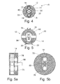
- the Fig. 4 shows an alternative embodiment of a fluid conveying arrangement 15 which, depending on the relative rotation between the primary side 12 and the secondary side 18 fluid circulates fluid between the two fluid pressure accumulator assemblies 42, 44.
- fluid delivery assembly 15 is constructed in the manner of a gear pump and has on the primary side 12, here represented by the housing part 14, two rotatably supported gears 76, 78 on. Between these, a gear 80 is provided centrally, also centrically to the axis of rotation A, which is assigned to the secondary side 18, for example, with the rotating portion 50 of the rotary feedthrough 46 is coupled.
- a pumping area is formed, which promotes fluid between the respective connecting chambers, represented here by the associated openings 33, 33 'and 35, 35'.
- fluid is conveyed via the openings 33, 33 'out of the connecting chambers 32, 32' associated therewith into the openings 35, 35 'and thus the connecting chambers 34, 34' associated therewith.
- Those connecting chambers, which receive the first fluid thus experience an increase in pressure, so that there will occur a correspondingly increased load on the associated gas spring units.
- a fluid conveying assembly 15 has the advantage that it can operate in a continuous rotation, which basically allows the setting of a relatively soft characteristic, since the hitting of components of the primary side and the secondary side can not occur here.
- a corresponding functionality is in the in the Fig. 5, 5a, 5b shown further alternative embodiment of a fluid conveying arrangement 15.
- a rotary piston pump with two counter-rotating rotary pistons 82, 84 is provided on the primary side 12, for example, again are rotatably disposed in the housing part 14.
- the drive of these rotary pistons 82, 84 can be achieved for example by a formation, as in the embodiment of the Fig. 4 is used as a gear pump.
- Each of the rotary pistons 82, 84 can thus be rotatably connected to one of the gears 76, 78, which are then driven to rotate again by the secondary-side central gear 80 during relative rotation between the primary side 12 and the secondary side 18.
- recognizable fluid delivery system promotes fluid, for example via the openings 33, 33 'in the openings 35, 35' or vice versa, with a corresponding reverse relative rotation between the primary side and the secondary side.
- FIG. 5 An advantage of in Fig. 5
- the arrangement shown is a better ratio between pump volume and size.
- the mutual sealing between the high pressure side and the low pressure side is easier to realize here due to the smaller number of surfaces to be sealed with respect to each other compared to a gear pump.
- Each of the two in the 4 and 5 shown variant of a fluid conveyor assembly can of course be in the in Fig. 1 and 2 shown construction of a torsional vibration damper assembly 10 are used in place of the variant realized with pressure chambers and wing-like walls.
- the Fig. 6 shows an alternative embodiment of a throttle assembly 60, here with a rotatable throttle element 62 a.
- This is a working with pressurized fluid drive unit 64a associated with two with pressurized fluid, such as oil or gas, pressure chambers 90, 92 assigned.
- pressurized fluid such as oil or gas
- pressure chambers 90, 92 By adjusting the pressure difference in these two pressure chambers 90, 92, it becomes possible to generate a torque, which the throttle element 62 a between the in Fig. 6 shown position with maximum throttle effect and in Fig. 8 shown adjusted position with minimal throttle effect.
- a small flow area 94 remains, over which also in This state still a small amount of the first fluid can flow to realize at least a minimum functionality of an associated gas spring unit 16.
- the in Fig. 6 illustrated state of the flow path to the associated gas spring unit 16 are also completely completed.
- the head region 96 of the throttle element 62a By configuring the head region 96 of the throttle element 62a with the tapered configuration, in particular by selecting the angle of inclination or also the shape of the bevel, it becomes possible to predefine the throttle characteristic of this throttle element 62a in accordance with the corresponding requirements.
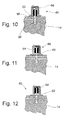
- the 10 to 12 show the embodiment of a throttle unit 60 again with a displaceable in its longitudinal direction throttle element 62 and an associated, for example, spring-biased drive unit 64.
- the supply of point energy can so as with reference to the Fig. 1 explained, so for example via the sliding contact arrangement 66 done.
- the valve element 62 is here formed with two head regions 96, 96 '. Depending on the shift state, head region 96 obstructs the fluid flow path to an associated gas spring unit or head region 96 'or, as shown in FIG Fig. 11 It can be seen that none of these head regions 96, 96 'lies in the flow path, for example in the respectively assigned connection chamber, so that an involved gas spring unit 16 can be effective for storing energy.
- the shape also influences this the two head regions 96, 96 'or their bevel or the control edges thus formed, the throttle behavior of the respective throttle assembly 60 upon displacement of the throttle element 62nd
- the Fig. 13 to 15 show the embodiment of a throttle unit 60 with a deformable throttle element 62b.
- This throttle element 62b designed, for example, in the form of a hollow body can lie between a support element 98 and a plunger 100 in an opening 39 or the flow path to an associated gas spring unit 16.
- the plunger 100 is displaceable and a displacement thereof radially inward leads to the in the FIGS. 14 and 15 recognizable deformation of the throttle element 62b, which increasingly pinch off the flow path.
- the movement of the plunger 100 in turn is achieved in the example shown by a bimetallic element 102.
- the deformable throttle element 62b and its plunger 100 can also be controlled in another way, for example by an electromagnetically acting drive unit, as in Fig. 2 is shown.
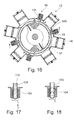
- the Fig. 16 shows one of the Fig. 2 corresponding representation of a Torsionsschwingungsdämpferan extract 10 in cross-section with four throttle units 60.
- These throttle units 60 are configured to generate a field, for example, an electric or a magnetic field when electrical excitation, which in turn impairs the viscosity of the first fluid.
- the throttle assemblies 60 configured with respective electromagnet assemblies 104, which thus generate a magnetic field upon electrical excitation, which is like 106 in the Fig. 16 can be seen, in the region of a respective opening 39 hineinerstreckt or in particular also within a connection chamber 37, and the first fluid is magneto-rheological, so increases by the magnetic field whose viscosity, ie, the toughness increases. This means that the openings 39 provide a greater flow resistance by interaction with a now tougher first fluid and correspondingly increases the throttle effect.
- FIGS. 17 and 18 show a respective solenoid unit 104 surrounding a line 108 through which magneto-rheological fluid flows.
- the magneto-rheological fluid contains magnetic or magnetizable metal particles 110, for example. Upon excitation of the electromagnet unit 108, these will align or preferably accumulate in the region of the magnetic field generated in this way and thus make it more difficult to flow through in the area of the magnetic field.
- the magneto-rheological fluid can move substantially unhindered through the conduit 108 in the region of the solenoid unit 104 therethrough.
- the various components in particular the radially outer member 20, in which these throttle assemblies 60 are formed, should be constructed of non-magnetizable material, such as aluminum.
- an electro-rheological fluid can be used, in which case the throttle units 60 for generating an electric field, that is, for example, the provision of a specific electrical potential, are formed.
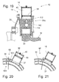
- a respective throttle assembly 60 includes a pivotable throttle element 62c, here formed in the form of a throttle valve in a respective connection chamber 37.
- the throttle element 62c is formed as a lever drive drive unit 64c assigned.
- This drive unit 64c comprises a drive lever 112 connected to a pivot axis 110 of the throttle element 62c and pivotally coupled thereto a transmission rod 114. The latter is pivotally supported on the secondary side 18.
- the throttle element 62c between the in Fig. 20 shown release position and the in Fig. 21 shown closed position and thereby the throttle behavior and thus the functionality of a respective gas spring unit 16 adjusted.
- FIGS. 22 to 24 show an embodiment variant of a torsional vibration damper assembly in which in turn a rotatable throttle element 62d of a respective throttle assembly 60 is provided in a connection chamber 37 and thus the flow path of the first fluid to a associated gas spring unit 16 can constrict more or less strong.
- the or each throttle element 62d is associated with a cam drive as drive unit 64d. This includes a rotatable with the throttle element 62d cam member 116 having a cam surface 118.
- a counter cam member 120 is provided with a counter cam surface 122.
- a basic rotational position of a throttle element can be predetermined by a spring-like and not shown in the figures biasing element, against which then cooperate the cam member 116 and the counter-cam member 120 for rotating the throttle element.
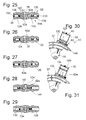
- a throttle arrangement 60 is in the Fig. 25 to 27 shown.
- This comprises a displaceable throttle element 62e with a throttle opening 124 which can be more or less brought into alignment with a channel leading to a gas spring unit, for example provided by an opening 39.
- the throttle element 62e is received in a substantially circumferentially or tangentially extending bore or opening 126.
- drive masses 128, 130 of the working here by centrifugal force drive unit 64e are provided.
- Each of these two drive masses 128, 130 is disposed between two springs 132, 134 and 136, 138, wherein the springs 132, 134 and 136, 138 are fixedly supported at their ends remote from the associated drive masses 128, 130 and thus the drive masses 128, 130 between the two springs 132, 134 and 136, 138 can oscillate back and forth.
- Each drive mass 128, 130 thus forms with the associated springs 132, 134, 136, 138 a vibration system with a defined resonance frequency.
- each drive mass 128, 130 has a drive tappet 140, 142, via which it can act on the displaceable valve element 62e.
- This is movable in the opening 126 against a defined frictional resistance, so that it is not itself, triggered by rotational accelerations is shifted, if not one of the drive masses 128 or 130 via the respective plunger 140 and 142 acts on the throttle element 62e.
- FIGS. 28 and 29 show one also in the FIGS. 30 and 31 in a torsional vibration damper assembly 10 built-in design in which only one vibration system, namely a drive mass 130 and an associated spring 134, is present to apply the valve element 62e here against the restoring force of a return spring 144.
- the return spring 144 basically shifts the throttle element 62e to a state in which the flow path to a respective gas spring unit 16 is blocked, as well as the Fig. 30 shows.
- the throttle unit 60 is arranged in the transition from a connection chamber 37 to a gas spring unit 16, that is to say at an opening 146. In this embodiment could be completely dispensed with the connection chambers 37 and then directly created via the opening 146 a connection to a respective connection chamber.
- the Fig. 32 shows one with respect to its construction essentially in Fig. 2 shown corresponding Torsionsschwingungsdämpferan Aunt 10 with a plurality of throttle assemblies 60 in association with gas spring units 16. While in the in Fig. 2 the arrangement shown, the control of the throttle units 60 via the sliding contact arrangement or sliding contact arrangements takes place, so here is a constant contact between a rotating and a non-rotating system area is present in the Fig. 32 an inductive transmission of drive signals or the excitation energy provided.
- an induction transmitter 150 is fixed with an induction antenna 152, for example in a transmission bell.
- the induction antenna emits electromagnetic signals which are received in a receive antenna 154 provided on the outer circumference of the primary side 12 of the torsional vibration damper arrangement 10.
- control signals can be filtered out, which are used in a control unit 156 to excite or de-energize the respectively addressed or to be controlled drive units 64.
- the signals transmitted to the drive unit 56 can be coded in order to transmit in this way the information which is to be excited to the drive units 64.
- a plurality of receiving antennas 64 can also be provided in association with the drive units 64 which can be controlled separately from one another in order to operate, for example, with transmission signals in different frequency ranges.
- the Fig. 33 shows a design variant, in which in principle the structure again the previous with reference to the Fig. 2 corresponds described.
- the electromagnetically active drive units 64 of the throttle arrangements 60 are supplied via one or more sliding contact arrangements 66 with electrical energy.
- an inertia switch 160 is provided in association with individual, groups or all throttle arrangements 60. This has an oscillating mass 162, the corresponding strong deflection, as in Fig. 34 is shown, the contact within the inertia switch 160 closes and thus energized coupled thereto a drive unit 64. In the absence of deflection of the inertial mass 162, the contact is open and the corresponding drive unit 62 is not energized.
- an arrangement is shown in which, depending on the rotational acceleration, an activation of the drive units 64 or correspondingly also a connection or disconnection of the gas spring units 16 can take place.
- the design could again be such that when the vibration system essentially formed by the inertia 162 in a resonant frequency range, ie a periodic excitation of the drive units 64, they remain by appropriate friction guidance of a respective throttle element 62 in a corresponding setting state.
- the Fig. 36 shows a Torsionsschwingungsdämpferan Aunt 10 with their star-shaped gas spring units 16 and some of them again associated with throttle assemblies 60.
- These include slidable throttle elements 62f and 62g, for example, as in Fig. 36 recognizable below and above, are biased in a the associated opening 39 final positioning.
- de throttle elements 62f, 62g carry magnetic interaction areas 170.
- drive units 64f fixed in the region of a gear bell, for example, or in another embodiment 64g.
- the drive units 64f act electromagnetically, thus generating a magnetic field when excited when moving past the magnetic interaction areas attracts 170, thus therefore the associated throttle elements 62f moves radially outward. These are biased counter to a certain frictional force in their closed position, so that between the time phases in which the magnetic interaction areas 170 pass by such drive units 64f, the throttle elements 62f can not reach their closed position. Only when the drive units 64f are no longer energized, and therefore no magnetic field pulls the throttle elements 62f radially outward, they reach their closed position and disconnect the associated gas spring units 16 from.
- the drive units 64g include permanent magnets 172, which may be radially displaced, for example under the control of a fluid pressure in fluid actuation units 174. If the permanent magnets 172 retreated radially outward, the magnetic interaction with the magnetic interaction regions 170 is too weak to be able to pull the throttle elements 62g radially outward. If, however, the permanent magnets 172 are displaced radially inwards, the distance between these permanent magnets 172 and the magnetic interaction areas 170 is so small during the periodic passing movement that the throttle elements 62g are pulled radially outwards and thus release the associated openings 39.
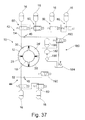
- the Fig. 37 shows an example of such a torsional vibration damper assembly 10, wherein in association with the Glastown effective pressure chambers 26, 26 'four gas spring units 16 are provided and in association with the thrust side effective pressure chambers 28, 28', for example, two gas spring units are provided.
- a source of pressurized first fluid generally designated 180, having a fluid pump 182 which removes fluid from a non-pressurized reservoir 184 via a filter 186 to supply, for example, an accumulator 188.
- Two switchable valve arrangements 190, 192 are provided, via which the two fluid pressure accumulator arrangements 42, 44 or their pressure chambers, connecting chambers and also connection chambers can be brought into connection either with the pressure accumulator 188 or the substantially unpressurized reservoir 184.
- another position of these valves 190, 192 could be provided in which they completely shut off the flow path and thus decouple the associated fluid pressure accumulator assemblies 42, 44 from both the pressure accumulator 188 and the reservoir 184.
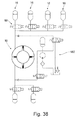
- Fig. 38 an arrangement in which the respective thrust side or zugmen effective gas spring units 16 act on the throttle assemblies associated therewith 60 parallel, so each of these gas spring units 16 may be effective alone or in combination with any other.
- the arrangement shown ultimately also corresponds to that, as for example in Fig. 2 It is shown where the individual gas spring units which can be switched on or off can be activated or deactivated in parallel with one another and in each case independently of how the others are connected.
- a flow path opens into a connecting path between a respective throttle arrangement 60 and a gas spring unit 16, which realizes the connection to the next following gas spring unit 16 or its throttle arrangement 60.
Landscapes
- Engineering & Computer Science (AREA)
- General Engineering & Computer Science (AREA)
- Physics & Mathematics (AREA)
- Acoustics & Sound (AREA)
- Aviation & Aerospace Engineering (AREA)
- Mechanical Engineering (AREA)
- Vibration Prevention Devices (AREA)
Applications Claiming Priority (1)
| Application Number | Priority Date | Filing Date | Title |
|---|---|---|---|
| DE200810001493 DE102008001493A1 (de) | 2008-04-30 | 2008-04-30 | Torsionsschwingungsdämpferanordnung für den Antriebsstrang eines Fahrzeugs |
Publications (1)
| Publication Number | Publication Date |
|---|---|
| EP2113682A2 true EP2113682A2 (fr) | 2009-11-04 |
Family
ID=40810134
Family Applications (1)
| Application Number | Title | Priority Date | Filing Date |
|---|---|---|---|
| EP20090158423 Withdrawn EP2113682A2 (fr) | 2008-04-30 | 2009-04-22 | Agencement d'amortissement des oscillations de torsion pour la chaîne cinématique d'un véhicule |
Country Status (2)
| Country | Link |
|---|---|
| EP (1) | EP2113682A2 (fr) |
| DE (1) | DE102008001493A1 (fr) |
Cited By (2)
| Publication number | Priority date | Publication date | Assignee | Title |
|---|---|---|---|---|
| WO2019122702A1 (fr) * | 2017-12-21 | 2019-06-27 | Valeo Embrayages | Dispositif de transmission de couple |
| WO2019122638A1 (fr) * | 2017-12-21 | 2019-06-27 | Valeo Embrayages | Dispositif de transmission de couple |
Families Citing this family (2)
| Publication number | Priority date | Publication date | Assignee | Title |
|---|---|---|---|---|
| DE102018210984A1 (de) * | 2018-07-04 | 2020-01-09 | Zf Friedrichshafen Ag | Dämpfungsvorrichtung für einen Triebstrang sowie Prüfstand mit der Dämpfungsvorrichtung |
| DE102021100431A1 (de) | 2021-01-12 | 2022-07-14 | Hasse & Wrede Gmbh | Drehschwingungsdämpfer oder Drehschwingungstilger |
Family Cites Families (2)
| Publication number | Priority date | Publication date | Assignee | Title |
|---|---|---|---|---|
| DE3726926C1 (de) * | 1987-08-13 | 1989-02-02 | Ulrich Dr-Ing Rohs | Vorrichtung zur AEnderung der zeitlichen Durchflussmenge eines fluessigen Daempfungsmittels bei einem Drehschwingungsdaempfer |
| ATE520897T1 (de) * | 2006-02-11 | 2011-09-15 | Schaeffler Technologies Gmbh | Drehschwingungsdämpfungseinrichtung |
-
2008
- 2008-04-30 DE DE200810001493 patent/DE102008001493A1/de not_active Withdrawn
-
2009
- 2009-04-22 EP EP20090158423 patent/EP2113682A2/fr not_active Withdrawn
Cited By (4)
| Publication number | Priority date | Publication date | Assignee | Title |
|---|---|---|---|---|
| WO2019122702A1 (fr) * | 2017-12-21 | 2019-06-27 | Valeo Embrayages | Dispositif de transmission de couple |
| WO2019122638A1 (fr) * | 2017-12-21 | 2019-06-27 | Valeo Embrayages | Dispositif de transmission de couple |
| FR3075907A1 (fr) * | 2017-12-21 | 2019-06-28 | Valeo Embrayages | Dispositif de transmission de couple |
| FR3075903A1 (fr) * | 2017-12-21 | 2019-06-28 | Valeo Embrayages | Dispositif de transmission de couple |
Also Published As
| Publication number | Publication date |
|---|---|
| DE102008001493A1 (de) | 2009-11-05 |
Similar Documents
| Publication | Publication Date | Title |
|---|---|---|
| EP3568606B1 (fr) | Module hybride pour un véhicule à moteur et chaîne cinématique dotée d'un module hybride | |
| DE10034677A1 (de) | Mehrfachkupplungsanordnung | |
| EP1715216B1 (fr) | Amortisseur de vibrations torsionelles | |
| DE102005058531A1 (de) | Torsionsschwingungsdämpfer | |
| EP2912336B1 (fr) | Ensemble amortisseur de vibrations de torsion avec dérivation de puissance | |
| DE102007049072A1 (de) | Phasenversteller für eine Brennkraftmaschine mit einer Oldham-Kupplung | |
| EP2600030A2 (fr) | Convertisseur de couple | |
| EP0803659B1 (fr) | Vilebrequin avec amortissuer de vibrations | |
| DE102008034557A1 (de) | Vorrichtung zur Dämpfung von Schwingungen, insbesondere mehrstufiger Drehschwingungsdämpfer | |
| EP2212587B1 (fr) | Dispositif d'accouplement hydrodynamique | |
| DE10005996A1 (de) | Drehmomentübertragungseinheit | |
| EP2702296A1 (fr) | Ensemble de transmission de couple de rotation | |
| DE102010050814A1 (de) | Getriebeeinrichtung und Nockenwellenversteller mit einer solchen Getriebeeinrichtung | |
| WO2017028858A1 (fr) | Pendule à force centrifuge et convertisseur de couple hydrodynamique équipé d'un pendule à force centrifuge | |
| EP3084248B1 (fr) | Dispositif d'embrayage à hydraulique entièrement intégrée | |
| DE102008001493A1 (de) | Torsionsschwingungsdämpferanordnung für den Antriebsstrang eines Fahrzeugs | |
| DE102008008508A1 (de) | Torsionsschwingungsdämpfer für den Antriebsstrang eines Fahrzeugs | |
| DE3939650C2 (fr) | ||
| DE102007014831B4 (de) | Kupplungsaktuatorik mit einer Unterstützungseinrichtung und Kupplung mit einer solchen Kupplungsaktuatorik | |
| EP0926391A2 (fr) | Embrayage élastique | |
| EP1584838B1 (fr) | Amortisseur de vibrations de torsion | |
| EP2623813B1 (fr) | Accouplement d'arbre elastique à caractéristique adaptive | |
| DE102005006232B3 (de) | Sperrkupplung mit Steuerung durch magnetorheologisches Fluid | |
| EP3405695A1 (fr) | Ensemble d'amortissement de vibrations de torsion pour transmission de véhicule | |
| EP1589256B1 (fr) | Amortisseur de vibrations torsionelles |
Legal Events
| Date | Code | Title | Description |
|---|---|---|---|
| PUAI | Public reference made under article 153(3) epc to a published international application that has entered the european phase |
Free format text: ORIGINAL CODE: 0009012 |
|
| AK | Designated contracting states |
Kind code of ref document: A2 Designated state(s): AT BE BG CH CY CZ DE DK EE ES FI FR GB GR HR HU IE IS IT LI LT LU LV MC MK MT NL NO PL PT RO SE SI SK TR |
|
| STAA | Information on the status of an ep patent application or granted ep patent |
Free format text: STATUS: THE APPLICATION IS DEEMED TO BE WITHDRAWN |
|
| 18D | Application deemed to be withdrawn |
Effective date: 20111101 |